EP1457724A2 - Valve with motor actuation - Google Patents
Valve with motor actuation Download PDFInfo
- Publication number
- EP1457724A2 EP1457724A2 EP04380020A EP04380020A EP1457724A2 EP 1457724 A2 EP1457724 A2 EP 1457724A2 EP 04380020 A EP04380020 A EP 04380020A EP 04380020 A EP04380020 A EP 04380020A EP 1457724 A2 EP1457724 A2 EP 1457724A2
- Authority
- EP
- European Patent Office
- Prior art keywords
- valve
- magnetic
- valve pin
- pin
- motor
- Prior art date
- Legal status (The legal status is an assumption and is not a legal conclusion. Google has not performed a legal analysis and makes no representation as to the accuracy of the status listed.)
- Granted
Links
- 230000005291 magnetic effect Effects 0.000 claims abstract description 48
- 230000003993 interaction Effects 0.000 claims abstract description 16
- 230000004913 activation Effects 0.000 claims abstract description 3
- XLYOFNOQVPJJNP-UHFFFAOYSA-N water Substances O XLYOFNOQVPJJNP-UHFFFAOYSA-N 0.000 description 9
- 230000009471 action Effects 0.000 description 1
- 230000008859 change Effects 0.000 description 1
Images


Classifications
-
- F—MECHANICAL ENGINEERING; LIGHTING; HEATING; WEAPONS; BLASTING
- F16—ENGINEERING ELEMENTS AND UNITS; GENERAL MEASURES FOR PRODUCING AND MAINTAINING EFFECTIVE FUNCTIONING OF MACHINES OR INSTALLATIONS; THERMAL INSULATION IN GENERAL
- F16K—VALVES; TAPS; COCKS; ACTUATING-FLOATS; DEVICES FOR VENTING OR AERATING
- F16K31/00—Actuating devices; Operating means; Releasing devices
- F16K31/02—Actuating devices; Operating means; Releasing devices electric; magnetic
- F16K31/04—Actuating devices; Operating means; Releasing devices electric; magnetic using a motor
- F16K31/047—Actuating devices; Operating means; Releasing devices electric; magnetic using a motor characterised by mechanical means between the motor and the valve, e.g. lost motion means reducing backlash, clutches, brakes or return means
-
- F—MECHANICAL ENGINEERING; LIGHTING; HEATING; WEAPONS; BLASTING
- F16—ENGINEERING ELEMENTS AND UNITS; GENERAL MEASURES FOR PRODUCING AND MAINTAINING EFFECTIVE FUNCTIONING OF MACHINES OR INSTALLATIONS; THERMAL INSULATION IN GENERAL
- F16K—VALVES; TAPS; COCKS; ACTUATING-FLOATS; DEVICES FOR VENTING OR AERATING
- F16K31/00—Actuating devices; Operating means; Releasing devices
- F16K31/02—Actuating devices; Operating means; Releasing devices electric; magnetic
- F16K31/04—Actuating devices; Operating means; Releasing devices electric; magnetic using a motor
- F16K31/046—Actuating devices; Operating means; Releasing devices electric; magnetic using a motor with electric means, e.g. electric switches, to control the motor or to control a clutch between the valve and the motor
-
- G—PHYSICS
- G05—CONTROLLING; REGULATING
- G05D—SYSTEMS FOR CONTROLLING OR REGULATING NON-ELECTRIC VARIABLES
- G05D16/00—Control of fluid pressure
- G05D16/20—Control of fluid pressure characterised by the use of electric means
- G05D16/2006—Control of fluid pressure characterised by the use of electric means with direct action of electric energy on controlling means
- G05D16/2013—Control of fluid pressure characterised by the use of electric means with direct action of electric energy on controlling means using throttling means as controlling means
- G05D16/202—Control of fluid pressure characterised by the use of electric means with direct action of electric energy on controlling means using throttling means as controlling means actuated by an electric motor
Definitions
- the present invention relates to a valve with motor drive, especially with a valve Motor drive for gas flow control one Hot water device, which essentially consists of one Valve lever and one with this valve lever connected valve stem, being a Has magnetic switch outside on the valve body and a movable with this valve pin Has magnetic element in the valve body, so if the valve pin up to a determined optimal Opening state is moved, the magnetic element with the magnetic switch interact to the Shut off the valve-driven engine so that the Valve pin to this found advantageous To be able to hold the opening position.
- the engine arranged outside on the valve body so that all electrical circuits of the gas flow valve with the gas supply can be isolated to a safe control of a gas flow To ensure hot water equipment.
- the moving magnet Under electrically switched on state of the solenoid can the moving magnet is directed towards the firmly attached magnet are tightened so that the am Movable magnet built-in valve pin on the by the direction of the valve opening can move to to open the valve opening so that the gas from Gas inlet through the open passage between the Valve pin and the valve opening and through the Gas outlet can be supplied in a gas burner.
- the opening of the valve opening by tightening the Magnetic elements is affected, the valve opening opened quickly. Because of this, a advantageous damped gas flow control unfortunately not be ensured. With a sudden opening the gas is currently in the valve opening Hot water device (in the gas burner) supplied and there would be a danger of Flame.
- the Applicants of the present invention already have one procure another invention using a valve Motor drive for gas flow control so to design that a cam gear with a Interaction element contributes to the Engine revolutions in a linear motion convert and the valve opening gradually slowly to be able to open a sudden gas supply to be able to rule out a risk of sudden Avoid flashlights after lighting a fire. Moreover the time of engine shutdown can change the position of the Influence the valve pin directly.
- the invention is therefore the important task based on a motorized valve for Gas flow control of the type described above to design that a valve lever in the valve body connects with a valve pin and a motor-driven interaction element on the corresponding point opposite the valve lever having; that a first magnetic element and a second Magnetic element on the valve lever and Interacting element arranges.
- the Interaction element can be driven by the motor Move towards the valve pin.
- these two magnetic elements can through the electrical engagement of each other be tightened and the interchangeable element will at the same time by the motor drive in the Valve pin moved away from the direction. To this Way, the valve opening gradually for the Appropriately open gas supply.
- the invention is based on a further object Motorized valve for gas flow control of the type described so that a Has magnetic switch outside on the valve body and a movable with this valve pin Has magnetic element in the valve body, so if the valve pin up to a determined optimal Opening state is moved, the magnetic element with the magnetic switch interact to the Shut off the valve-driven engine so that the Valve pin to this found advantageous To be able to hold the opening position.
- an object of the invention is to have a valve Motor drive for gas flow control of the input described type so that the engine located outside on the valve body so that all electrical circuits of the gas flow valve with the gas supply can be isolated to a safe control of a gas flow To ensure hot water equipment.
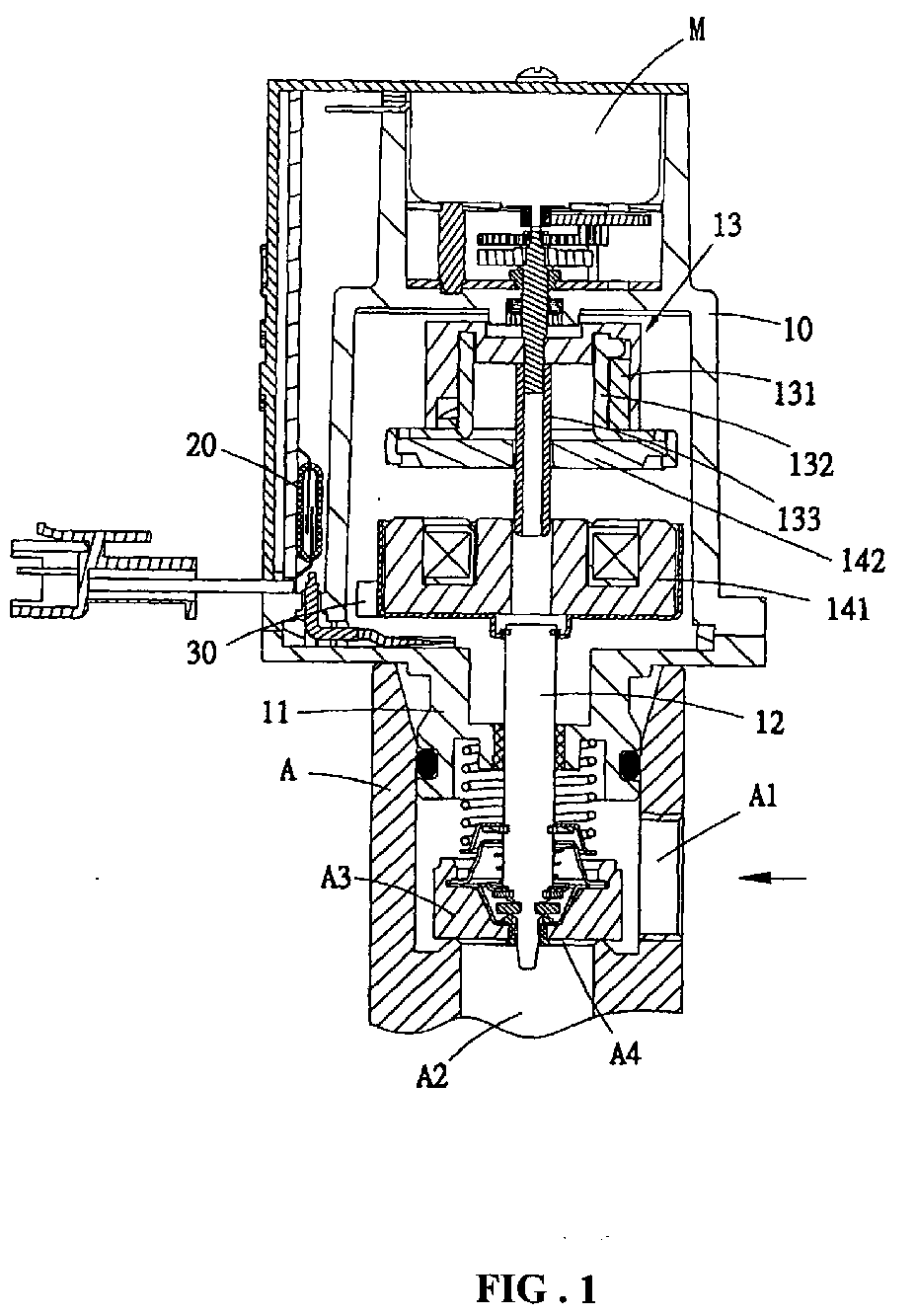
- FIG. 1 An inventive valve with motor drive for Gas flow control essentially exists as in Fig. 1 can be seen from a with the gas valve housing (A) connected valve body (10), one Connection stubs (11), a valve lever (12), a Valve pin (A3) and a valve opening (A4).
- the main valve part (10) is with a connecting piece (11) for connection to the gas valve housing (A) designed.
- the gas valve housing (A) includes one Gas inlet (A1) and a gas outlet (A2).
- the Valve opening (A4) is in the gas inlet (A1) and gas outlet (A2) arranged passage and can be covered by the valve pin (A3).
- the valve stem (A3) can be moved in by the motor drive separate the direction facing away from the valve opening (A4) be moved to the passage between the gas inlet (A1) and the gas outlet (A2) to open a to allow optimal control of the gas supply.
- the valve lever (12) is in the main valve part (10) arranged and is connected to the valve pin (A3).
- the one driven by a motor (M) Interaction element (13) is the most appropriate Place opposite the valve lever (12) and consists essentially of a cam housing (131), a crank rod (133) and a movable one Cam disc (132).
- a first magnetic element (141) and a second magnetic element (142) each on the valve lever (12) and on the cam disc (132) of the Interaction element (13) are arranged so when the interaction element (13) by the drive of the motor (M) up to the position of contact from the above two first and second magnetic elements (141, 142) reached, these two magnetic elements (141, 142) by the electrical switch-on are attracted to each other (as shown in Fig. 2 represents) and the interchangeable element (13) can at the same time by the motor drive (M) Cam disc (132) in the from the valve pin (A3) moved away. In this way, the Valve opening (A4) gradually optimal for the gas supply open.
- a magnetic switch (20) in the form of a Nominal activation outside of the valve body (10) can be arranged and one with this valve pin (A3) movable magnetic element (30) in the valve main part (10) can be arranged so that when the valve pin (A3) up to moved to a determined opening state, can the magnetic element (30) with the magnetic switch (20) cooperate around the valve pin (A3) shut off the driven engine so that the valve pin (A3) to this advantageous found To be able to hold the opening position.
- valve is included Motor drive good gas flow control properties, wherein the valve stem by the action of a Magnetic switch found an optimal Can achieve opening condition and at the same time to be able to turn off the motor drive so that the Valve pin to this found advantageous To be able to hold the opening position. That is why present invention practically for use.
Landscapes
- Engineering & Computer Science (AREA)
- General Engineering & Computer Science (AREA)
- Physics & Mathematics (AREA)
- Mechanical Engineering (AREA)
- Fluid Mechanics (AREA)
- Automation & Control Theory (AREA)
- General Physics & Mathematics (AREA)
- Electrically Driven Valve-Operating Means (AREA)
- Magnetically Actuated Valves (AREA)
- Mechanically-Actuated Valves (AREA)
- Valve Device For Special Equipments (AREA)
- Exhaust-Gas Circulating Devices (AREA)
- Feeding And Controlling Fuel (AREA)
Abstract
Ein Ventil mit Motorantrieb für
Gasdurchflußsteuerung, umfasst einen Ventilhebel (12) und
einen Ventilzapfen (A3), wobei der Ventilhebel (12) im
Ventilhauptteil mit diesem Ventilzapfen (A3) verbindet und
ein motorgetriebenes Wechselwirkungselement (13) an der
entsprechenden Stelle gegenüber dem Ventilhebel
aufweist; ein erstes Magnetelement (141) und ein zweites
Magnetelement (142) jeweils am Ventilhebel und am
Wechselwirkungselement anordnet; das
Wechselwirkungselement durch den Motorantrieb in
Richtung auf den Ventilzapfen bewegen kann; sobald das
Wechselwirkungselement bis die Stellung der Berührung
von o. g. beiden ersten und zweiten Magnetelementen
erreicht, können diese beiden Magnetelementen sich
durch die elektrische Einschaltung gegenseitig
angezogen werden und das Wechselelement gleichzeitig
dabei durch den Motorantrieb in die vom Ventilzapfen
abgewandte Richtung bewogen wird und auf diese Weise
die Ventilöffnung allmählich für die Gaszufuhr
geöffnet, dadurch gekennzeichnet, daß ein
Magnetschalter (20) außerhalb am Ventilhauptteil aufweist
und ein mit diesem Ventilzapfen bewegbares
Magnetelement im Ventilhauptteil aufweist, damit wenn
der Ventilzapfen bis zu einem festgestellten
Öffnungszustand bewegt ist, kann das Magnetelement mit
dem Magnetschalter zusammenwirken, um den den
Ventilzapfen antriebenen Motor abzustellen, damit der
Ventilzapfen zu diesem festgestellten vorteilhaften
Öffnungsstand halten zu können.
Description
Die vorliegende Erfindung bezieht sich auf ein Ventil mit Motorantrieb, insbesondere auf ein Ventil mit Motorantrieb für Gasdurchflußsteuerung eines Heißwassergeräts, das im wesentlichen aus einem Ventilhebel und einem mit diesem Ventilhebel verbundenen Ventilzapfen besteht, wobei ein Magnetschalter außerhalb am Ventilhauptteil aufweist und ein mit diesem Ventilzapfen bewegbares Magnetelement im Ventilhauptteil aufweist, damit wenn der Ventilzapfen bis zu einem festgestellten optimalen Öffnungszustand bewegt ist, kann das Magnetelement mit dem Magnetschalter zusammenwirken, um den den Ventilzapfen antriebenen Motor abzustellen, damit der Ventilzapfen zu diesem festgestellten vorteilhaften Öffnungsstand halten zu können. Außerdem wird der Motor außerhalb am Ventilhauptteil angeordnet, damit alle elektrischen Schaltungen des Gasdurchflußventils mit der Gaszufuhr isoliert werden zu können, um eine sichere Steuerung des Gasdurchflusses eines Heißwassergeräts sicherstellen zu können.The present invention relates to a valve with motor drive, especially with a valve Motor drive for gas flow control one Hot water device, which essentially consists of one Valve lever and one with this valve lever connected valve stem, being a Has magnetic switch outside on the valve body and a movable with this valve pin Has magnetic element in the valve body, so if the valve pin up to a determined optimal Opening state is moved, the magnetic element with the magnetic switch interact to the Shut off the valve-driven engine so that the Valve pin to this found advantageous To be able to hold the opening position. In addition, the engine arranged outside on the valve body so that all electrical circuits of the gas flow valve with the gas supply can be isolated to a safe control of a gas flow To ensure hot water equipment.
Bekanntlich wird ein herkömmliches Magnetventil für Steuerung des Gasdurchflusses eines Heißwassergeräts im wesentlichen aus einer Magnetspule, einem festverbundenen Magnet, einem beweglichen Magnet und einem zusammenwirkenden Ventilzapfen besteht. Unter elektrisch eingeschaltetem Zustand der Magnetspule kann der bewegliche Magnet sich in Richtung auf den festverbundenen Magnet angezogen werden, damit der am beweglichen Magnet eingebaute Ventilzapfen auf die von der Ventilöffnung abgewandten Richtung bewegen kann, um die Ventilöffnung zu öffen, so daß das Gas vom Gaseinlaß über den geöffneten Durchgang zwischen dem Ventilzapfen und der Ventilöffnung und durch den Gasauslaß in einen Gasbrenner versorgt werden kann. Da die Öffnung der Ventilöffnung durch den Anzug der Magnetelemente beeinflußt wird, wird die Ventilöffnung dabei schnell geöffnet. Auf diesem Grund kann eine vorteilhafte gedämpfte Gasflußsteuerung leider nicht sichergestellt werden. Bei einer plötzlichen Öffnung der Ventilöffnung wird das Gas momentan ins Heißwassergerät (in den Gasbrenner) versorgt und bestünde es dabei eventuell eine Gefahr von Stichflamme.As is known, a conventional solenoid valve for Control the gas flow of a hot water device in the essentially from a magnetic coil, a firmly attached magnet, a movable magnet and there is a cooperating valve pin. Under electrically switched on state of the solenoid can the moving magnet is directed towards the firmly attached magnet are tightened so that the am Movable magnet built-in valve pin on the by the direction of the valve opening can move to to open the valve opening so that the gas from Gas inlet through the open passage between the Valve pin and the valve opening and through the Gas outlet can be supplied in a gas burner. There the opening of the valve opening by tightening the Magnetic elements is affected, the valve opening opened quickly. Because of this, a advantageous damped gas flow control unfortunately not be ensured. With a sudden opening the gas is currently in the valve opening Hot water device (in the gas burner) supplied and there would be a danger of Flame.
Um die oben erwähnten Nachteilen zu vermeiden, hat der Antragsteller der vorliegenden Erfindung bereits eine andere Erfindung beschaffen, ein Ventil mit Motorantrieb für Gasdurchflußsteuerung so auszugestalten, daß ein Nockengetriebe mit einem Wechselwirkungselement mitwirkt, um die Motorumdrehungen in eine linearen Bewegungen umzuwandeln und die Ventilöffnung allmählich langsam öffnen zu können, damit eine plötzliche Gasversorgung ausschließen zu können, um eine Gefahr von plötzlichen Stichflammen nach Feueranzündung zu vermeiden. Außerdem kann der Zeitpunkt der Motorabstellung die Stellung des Ventilzapfens direkt beeinfließen. Deswegen muß ein Schalter an der angemessenen Stellung des Hubs des Ventilzapfens angeordnet werden, um die Bewegung des Motors zu steuern, damit wenn der Ventilzapfen bis zu einem festgestellten Öffnungszustand bewegt ist, kann das Magnetelement mit dem Magnetschalter zusammenwirken, um den Ventilzapfen antriebenen Motor abzustellen, damit der Ventilzapfen zu diesem festgestellten vorteilhaften Öffnungsstand halten zu können.To avoid the disadvantages mentioned above, the Applicants of the present invention already have one procure another invention using a valve Motor drive for gas flow control so to design that a cam gear with a Interaction element contributes to the Engine revolutions in a linear motion convert and the valve opening gradually slowly to be able to open a sudden gas supply to be able to rule out a risk of sudden Avoid flashlights after lighting a fire. Moreover the time of engine shutdown can change the position of the Influence the valve pin directly. That's why one has to Switch at the appropriate position of the stroke of the Valve pin are arranged to prevent the movement of the Motor control, so when the valve stem is up to moved to a determined opening state, can the magnetic element with the magnetic switch cooperate to drive the valve stem motor turn off so the valve pin to this advantageous opening position determined hold can.
Der Erfindung liegt somit die wichtige Aufgabe zugrunde, ein Ventil mit Motorantrieb für Gasdurchflußsteuerung der eingangs geschilderten Art so auszugestalten, daß ein Ventilhebel im Ventilhauptteil mit einem Ventilzapfen verbindet und ein motorgetriebenes Wechselwirkungselement an der entsprechenden Stelle gegenüber dem Ventilhebel aufweist; daß ein erstes Magnetelement und ein zweites Magnetelement jeweils am Ventilhebel und am Wechselwirkungselement anordnet. Das Wechselwirkungselement kann durch den Motorantrieb in Richtung auf den Ventilzapfen bewegen. Sobald das Wechselwirkungselement bis zur Stellung der Berührung von o.g. beiden ersten und zweiten Magnetelementen erreicht, können diese beiden Magnetelementen sich durch die elektrische Einschaltung gegenseitig angezogen werden und das Wechselelement wird gleichzeitig dabei durch den Motorantrieb in die vom Ventilzapfen abgewandte Richtung bewogen. Auf diese Weise kann die Ventilöffnung allmählich für die Gaszufuhr zweckmäßig geöffnet.The invention is therefore the important task based on a motorized valve for Gas flow control of the type described above to design that a valve lever in the valve body connects with a valve pin and a motor-driven interaction element on the corresponding point opposite the valve lever having; that a first magnetic element and a second Magnetic element on the valve lever and Interacting element arranges. The Interaction element can be driven by the motor Move towards the valve pin. As soon as that Interaction element up to the position of the touch from the above two first and second magnetic elements reached, these two magnetic elements can through the electrical engagement of each other be tightened and the interchangeable element will at the same time by the motor drive in the Valve pin moved away from the direction. To this Way, the valve opening gradually for the Appropriately open gas supply.
Der Erfindung liegt eine weitere Aufgabe zugrunde, ein Ventil mit Motorantrieb für Gasdurchflußsteuerung der eingangs geschilderten Art so auszugestalten, daß ein Magnetschalter außerhalb am Ventilhauptteil aufweist und ein mit diesem Ventilzapfen bewegbares Magnetelement im Ventilhauptteil aufweist, damit wenn der Ventilzapfen bis zu einem festgestellten optimalen Öffnungszustand bewegt ist, kann das Magnetelement mit dem Magnetschalter zusammenwirken, um den den Ventilzapfen antriebenen Motor abzustellen, damit der Ventilzapfen zu diesem festgestellten vorteilhaften Öffnungsstand halten zu können.The invention is based on a further object Motorized valve for gas flow control of the type described so that a Has magnetic switch outside on the valve body and a movable with this valve pin Has magnetic element in the valve body, so if the valve pin up to a determined optimal Opening state is moved, the magnetic element with the magnetic switch interact to the Shut off the valve-driven engine so that the Valve pin to this found advantageous To be able to hold the opening position.
Schließlich ist ein Ziel der Erfindung, ein Ventil mit Motorantrieb für Gasdurchflußsteuerung der eingangs geschilderten Art so auszugestalten, daß der Motor außerhalb am Ventilhauptteil anordnet, damit alle elektrischen Schaltungen des Gasdurchflußventils mit der Gaszufuhr isoliert werden zu können, um eine sichere Steuerung des Gasdurchflusses eines Heißwassergeräts sicherstellen zu können.Finally, an object of the invention is to have a valve Motor drive for gas flow control of the input described type so that the engine located outside on the valve body so that all electrical circuits of the gas flow valve with the gas supply can be isolated to a safe control of a gas flow To ensure hot water equipment.
Die gestellten Aufgaben werden durch die in Schutzansprüchen angegebenen Merkmale gelöst.The tasks are performed by the in Protection claims specified features solved.
In der Zeichnung ist der Erfindungsgegenstand
beispielweise dargestellt. Es zeigen
Ein erfindungsgemäßes Ventil mit Motorantrieb für Gasdurchflußsteuerung besteht im wesentlichen, wie in Fig. 1 ersichtlich, aus einem mit dem Gasventilgehäuse (A) verbundenen Ventilhauptteil (10), einem Anschlußstuzten (11), einem Ventilhebel (12), einem Ventilzapfen (A3) und einer Ventilöffnung (A4).An inventive valve with motor drive for Gas flow control essentially exists as in Fig. 1 can be seen from a with the gas valve housing (A) connected valve body (10), one Connection stubs (11), a valve lever (12), a Valve pin (A3) and a valve opening (A4).
Der Ventilhauptteil (10) ist mit einem Anschlußstutzen (11) zur Verbindung mit dem Gasventilgehäuse (A) ausgestaltet. Das Gasventilgehäuse (A) umfasst einen Gaseinlaß (A1) und einen Gasauslaß (A2). Die Ventilöffnung (A4) ist im vom Gaseinlaß (A1) und gasauslaß (A2) ausgebildeten Durchgang angeordnet und kann durch den Ventilzapfen (A3) abgedeckt werden. Durch den Motorantrieb kann der Ventilzapfen (A3) in die von Ventilöffnung (A4) abgewandte Richtung getrennt bewegt werden, um den Durchgang zwischem dem Gaseinlaß (A1) und dem Gasauslaß (A2) zu öffnen, damit eine optimale Steuerung der Gaszufuhr zu ermöglichen.The main valve part (10) is with a connecting piece (11) for connection to the gas valve housing (A) designed. The gas valve housing (A) includes one Gas inlet (A1) and a gas outlet (A2). The Valve opening (A4) is in the gas inlet (A1) and gas outlet (A2) arranged passage and can be covered by the valve pin (A3). The valve stem (A3) can be moved in by the motor drive separate the direction facing away from the valve opening (A4) be moved to the passage between the gas inlet (A1) and the gas outlet (A2) to open a to allow optimal control of the gas supply.
Der Ventilhebel (12) ist im Ventilhauptteil (10) angeordnet und ist mit dem Ventilzapfen (A3) verbunden. Das durch einen Motor (M) angetriebene Wechselwirkungselement (13) ist an der angemessenen Stelle gegenüber dem Ventilhebel (12) angeordnet und besteht im wesentlichen aus einem Nockengehäuse (131), einer Kurbelstange (133) und einer bewegbaren Nockenscheibe (132).The valve lever (12) is in the main valve part (10) arranged and is connected to the valve pin (A3). The one driven by a motor (M) Interaction element (13) is the most appropriate Place opposite the valve lever (12) and consists essentially of a cam housing (131), a crank rod (133) and a movable one Cam disc (132).
Außerdem kann ein erstes Magnetelement (141) und ein zweites Magnetelement (142) jeweils am Ventilhebel (12) und an der Nockenscheibe (132) des Wechselwirkungselements (13) anordnet werden, damit wenn das Wechselwirkungselement (13) durch den Antrieb des Motors (M) bis zur Stellung der Berührung von o.g. beiden ersten und zweiten Magnetelementen (141, 142) erreicht, können diese beiden Magnetelementen (141, 142) sich durch die elektrische Einschaltung gegenseitig angezogen werden (wie es in Fig. 2 darstellt) und das Wechselelement (13) kann gleichzeitig dabei durch den Motorantrieb (M) der Nockenscheibe (132) in die vom Ventilzapfen (A3) abgewandte Richtung bewogen. Auf diese Weise kann die Ventilöffnung (A4) allmählich für die Gaszufuhr optimal geöffnet.In addition, a first magnetic element (141) and a second magnetic element (142) each on the valve lever (12) and on the cam disc (132) of the Interaction element (13) are arranged so when the interaction element (13) by the drive of the motor (M) up to the position of contact from the above two first and second magnetic elements (141, 142) reached, these two magnetic elements (141, 142) by the electrical switch-on are attracted to each other (as shown in Fig. 2 represents) and the interchangeable element (13) can at the same time by the motor drive (M) Cam disc (132) in the from the valve pin (A3) moved away. In this way, the Valve opening (A4) gradually optimal for the gas supply open.
Ferner ist ein Magnetschalter (20) in Form einer Nenneinschaltung außerhalb am Ventilhauptteil (10) anordenbar und ein mit diesem Ventilzapfen (A3) bewegbares Magnetelement (30) im Ventilhauptteil (10) anordnenbar, damit wenn der Ventilzapfen (A3) bis zu einem festgestellten Öffnungszustand bewegt ist, kann das Magnetelement (30) mit dem Magnetschalter (20) zusammenwirken, um den den Ventilzapfen (A3) antriebenen Motor abzustellen, damit der Ventilzapfen (A3) zu diesem festgestellten vorteilhaften Öffnungsstand halten zu können.Furthermore, a magnetic switch (20) in the form of a Nominal activation outside of the valve body (10) can be arranged and one with this valve pin (A3) movable magnetic element (30) in the valve main part (10) can be arranged so that when the valve pin (A3) up to moved to a determined opening state, can the magnetic element (30) with the magnetic switch (20) cooperate around the valve pin (A3) shut off the driven engine so that the valve pin (A3) to this advantageous found To be able to hold the opening position.
Die Vorteile der Erfindung besteht darin, daß den vom Ventilzapfen (A3) geöffneten Zustand durch Magnetwirkung erzielen werden zu können und zwar kann der Magnetschalter (20) außerhalb am Ventilhauptteil (10) angeordnet, damit alle elektrischen Schaltungen des Gasdurchflußventils mit der Gaszufuhr isoliert werden zu können, um eine sichere Steuerung des Gasdurchflusses eines Heißwassergeräts sicherstellen zu können. Es ist auch möglich, der Motor (M) außerhalb dem Ventilhauptteil (10) anzuordnen, damit alle elektrischen Schaltungen des Gasdurchflußventils mit der Gaszufuhr isoliert werden zu können, um eine sichere Steuerung des Gasdurchflusses eines Heißwassergeräts sicherstellen zu können.The advantages of the invention is that the Valve pin (A3) opened by To be able to achieve magnetic effect and indeed can the magnetic switch (20) outside on the valve body (10) arranged so all electrical circuits of the gas flow valve isolated with the gas supply to be able to safely control the Ensure gas flow of a hot water device can. It is also possible to have the engine (M) outside the valve body (10) to arrange so that all electrical circuits of the gas flow valve with the gas supply can be isolated to a safe control of a gas flow To ensure hot water equipment.
Angesichts des obenstehenden schaft das Ventil mit Motorantrieb gute Gasdurchflußsteuerungseigenschaften, wobei der Ventilzapfen durch die Wirkung eines Magnetschalters einen optimalen festgestellten Öffnungszustand erzielen kann und gleichzeitig dabei den Motorantrieb abstellen zu können, damit der Ventilzapfen zu diesem festgestellten vorteilhaften Öffnungsstand halten zu können. Deshalb ist die vorliegende Erfindung praktisch zur Verwendung. Außerdem können alle elektrischen Schaltungen von einer Gaszufuhr isoliert angebracht werden, um eine sichere Steuerung des Gasdurchflusses eines Heißwassergeräts sicherstellen zu können.In view of the above, the valve is included Motor drive good gas flow control properties, wherein the valve stem by the action of a Magnetic switch found an optimal Can achieve opening condition and at the same time to be able to turn off the motor drive so that the Valve pin to this found advantageous To be able to hold the opening position. That is why present invention practically for use. In addition, all electrical circuits from one Gas supply insulated to ensure safe Control the gas flow of a hot water device to be able to ensure.
Die Bezeichnungen der Einzelteile der Ausführungsform nach der vorliegenden Erfindung sowie die Zeichnungen dienen lediglich zur Veranschaulichung der bevorzugten Ausführungsform der vorliegenden Erfindung und beschränklich sich nicht auf den Umfang der vorliegenden Erfindung. Es ist verständlich, daß die oben beschriebene Ausführungsform in verschiedener Weise ausgeführt werden kann, ohne daß dabei vom Sinn und Zweck der vorliegenden Erfindung abgesichern werden muß. Dementsprechend gelten die folgenden Schutzansprüche, die Teil dieser Erfindung sind, ebenfalls für sämtliche Abänderungen der Ausführungsform.The designations of the individual parts of the embodiment according to the present invention as well as the drawings serve only to illustrate the preferred Embodiment of the present invention and is not limited to the scope of the present invention. It is understandable that the Embodiment described above in various Way can be carried out without losing sense and purpose of the present invention got to. Accordingly, the following apply Protection claims that are part of this invention also for all changes of the Embodiment.
Es wird ein Ventil mit Motorantrieb für Gasdurchflußsteuerung beschrieben, das im wesentlichen aus einem Ventilhebel und einem mit diesem Ventilhebel verbundenen Ventilzapfen besteht, wobei ein Magnetschalter außerhalb am Ventilhauptteil aufweist und ein mit diesem Ventilzapfen bewegbares Magnetelement im Ventilhauptteil aufweist, damit wenn der Ventilzapfen bis zu einem festgestellten optimalen Öffnungszustand bewegt ist, kann das Magnetelement mit dem Magnetschalter zusammenwirken, um den den Ventilzapfen antriebenen Motor abzustellen, damit der Ventilzapfen zu diesem festgestellten vorteilhaften Öffnungsstand halten zu können. Außerdem wird der Motor außerhalb am Ventilhauptteil angeordnet, damit alle elektrischen Schaltungen des Gasdurchflußventils mit der Gaszufuhr isoliert werden zu können, um eine sichere Steuerung des Gasdurchflusses eines Heißwassergeräts sicherstellen zu können.It will be a motorized valve for Gas flow control described that essentially from a valve lever and one with this valve lever connected valve stem, being a Has magnetic switch outside on the valve body and a movable with this valve pin Has magnetic element in the valve body, so if the valve pin up to a determined optimal Opening state is moved, the magnetic element with the magnetic switch interact to the Shut off the valve-driven engine so that the Valve pin to this found advantageous To be able to hold the opening position. In addition, the engine arranged outside on the valve body so that all electrical circuits of the gas flow valve with the gas supply can be isolated to a safe control of a gas flow To ensure hot water equipment.
Claims (3)
Applications Claiming Priority (2)
| Application Number | Priority Date | Filing Date | Title |
|---|---|---|---|
| DE20303764U | 2003-03-10 | ||
| DE20303764U DE20303764U1 (en) | 2003-03-10 | 2003-03-10 | Motorized valve for gas flow control |
Publications (3)
| Publication Number | Publication Date |
|---|---|
| EP1457724A2 true EP1457724A2 (en) | 2004-09-15 |
| EP1457724A3 EP1457724A3 (en) | 2004-11-24 |
| EP1457724B1 EP1457724B1 (en) | 2007-05-30 |
Family
ID=7980663
Family Applications (1)
| Application Number | Title | Priority Date | Filing Date |
|---|---|---|---|
| EP04380020A Expired - Lifetime EP1457724B1 (en) | 2003-03-10 | 2004-01-28 | Valve with motor actuation |
Country Status (5)
| Country | Link |
|---|---|
| EP (1) | EP1457724B1 (en) |
| AT (1) | ATE363620T1 (en) |
| DE (2) | DE20303764U1 (en) |
| ES (1) | ES2286579T3 (en) |
| PT (1) | PT1457724E (en) |
Cited By (3)
| Publication number | Priority date | Publication date | Assignee | Title |
|---|---|---|---|---|
| KR100813112B1 (en) | 2006-04-25 | 2008-03-13 | 주식회사 맥코이 | Flow switchgear using permanent magnet |
| CN102705286A (en) * | 2012-05-25 | 2012-10-03 | 西安交通大学 | Balanced high-pressure large-current AC (Alternating Current) servo direct-driven cartridge valve |
| CN111417807A (en) * | 2018-01-31 | 2020-07-14 | 浙江三花制冷集团有限公司 | A kind of electric valve and the manufacturing method of electric valve |
Family Cites Families (4)
| Publication number | Priority date | Publication date | Assignee | Title |
|---|---|---|---|---|
| JPH0665912B2 (en) * | 1984-08-28 | 1994-08-24 | 宇部興産株式会社 | Flow control valve |
| DE19516054A1 (en) * | 1994-05-11 | 1995-11-16 | Kromschroeder Ag G | Controllable valve with stepping motor movable by electromagnet |
| DE4423313A1 (en) * | 1994-07-02 | 1996-01-04 | Pierburg Gmbh | Electrically-driven setting element with self-locking function |
| DE20216686U1 (en) * | 2002-10-29 | 2003-01-23 | PAUDEN Scientific & Technological Co., Ltd., Sanchung | Solenoid valve for gas flow |
-
2003
- 2003-03-10 DE DE20303764U patent/DE20303764U1/en not_active Expired - Lifetime
-
2004
- 2004-01-28 AT AT04380020T patent/ATE363620T1/en active
- 2004-01-28 ES ES04380020T patent/ES2286579T3/en not_active Expired - Lifetime
- 2004-01-28 PT PT04380020T patent/PT1457724E/en unknown
- 2004-01-28 EP EP04380020A patent/EP1457724B1/en not_active Expired - Lifetime
- 2004-01-28 DE DE502004003921T patent/DE502004003921D1/en not_active Expired - Lifetime
Cited By (4)
| Publication number | Priority date | Publication date | Assignee | Title |
|---|---|---|---|---|
| KR100813112B1 (en) | 2006-04-25 | 2008-03-13 | 주식회사 맥코이 | Flow switchgear using permanent magnet |
| CN102705286A (en) * | 2012-05-25 | 2012-10-03 | 西安交通大学 | Balanced high-pressure large-current AC (Alternating Current) servo direct-driven cartridge valve |
| CN111417807A (en) * | 2018-01-31 | 2020-07-14 | 浙江三花制冷集团有限公司 | A kind of electric valve and the manufacturing method of electric valve |
| CN111417807B (en) * | 2018-01-31 | 2022-04-26 | 浙江三花制冷集团有限公司 | Electric valve and manufacturing method thereof |
Also Published As
| Publication number | Publication date |
|---|---|
| ES2286579T3 (en) | 2007-12-01 |
| EP1457724A3 (en) | 2004-11-24 |
| DE502004003921D1 (en) | 2007-07-12 |
| PT1457724E (en) | 2007-07-24 |
| EP1457724B1 (en) | 2007-05-30 |
| DE20303764U1 (en) | 2003-05-22 |
| ATE363620T1 (en) | 2007-06-15 |
Similar Documents
| Publication | Publication Date | Title |
|---|---|---|
| DE3346290A1 (en) | MAGNETIC VALVE | |
| DE4409172A1 (en) | Safety device for the mutual mechanical locking of interrupter switches | |
| DE1463495A1 (en) | End position control unit | |
| EP0836886A1 (en) | Switching flap for deactivating the cutting device of a document shredder an the like apparatus | |
| EP1457724A2 (en) | Valve with motor actuation | |
| DE3121367C2 (en) | Device for locking and unlocking doors, in particular motor vehicle doors | |
| DE102010039009A1 (en) | Gas valve unit | |
| EP1903198B1 (en) | Device for operating the flap valve in an exhaust gas facility | |
| WO2012080051A2 (en) | Gas valve unit for a dual circuit burner | |
| EP2601445B1 (en) | Gas valve unit | |
| EP0716726B1 (en) | Magnet-actuated venting device | |
| WO2004031632A1 (en) | Gas tap comprising an electromagnetic safety valve and magnetic insert for an electromagnetic safety valve | |
| DE2615724C2 (en) | ||
| DE3915827C1 (en) | ||
| DE3708470C1 (en) | Actuating drive for a valve or the like | |
| DE2501806C2 (en) | Pressure or force sensitive switching arrangement | |
| DE19652975C2 (en) | Limit switch for a blind drive | |
| DE10334944B4 (en) | control valve | |
| DE2850291A1 (en) | SERVO-ACTUATED THREE-WAY VALVE | |
| DE4422302C1 (en) | Electrical power switch with display for state of energy storage stage | |
| DE10254177B3 (en) | Manual override device | |
| EP1445523A2 (en) | Valve with motor actuation for gas flow regulating | |
| DE2700983C2 (en) | Multi-way valve | |
| DE110764C (en) | ||
| DE684884C (en) | Electrical switch, especially limit switch for pitch adjustment of propellers |
Legal Events
| Date | Code | Title | Description |
|---|---|---|---|
| PUAI | Public reference made under article 153(3) epc to a published international application that has entered the european phase |
Free format text: ORIGINAL CODE: 0009012 |
|
| AK | Designated contracting states |
Kind code of ref document: A2 Designated state(s): AT BE BG CH CY CZ DE DK EE ES FI FR GB GR HU IE IT LI LU MC NL PT RO SE SI SK TR |
|
| AX | Request for extension of the european patent |
Extension state: AL LT LV MK |
|
| PUAL | Search report despatched |
Free format text: ORIGINAL CODE: 0009013 |
|
| AK | Designated contracting states |
Kind code of ref document: A3 Designated state(s): AT BE BG CH CY CZ DE DK EE ES FI FR GB GR HU IE IT LI LU MC NL PT RO SE SI SK TR |
|
| AX | Request for extension of the european patent |
Extension state: AL LT LV MK |
|
| 17P | Request for examination filed |
Effective date: 20050114 |
|
| 17Q | First examination report despatched |
Effective date: 20050324 |
|
| AKX | Designation fees paid |
Designated state(s): AT BE BG CH CY CZ DE DK EE ES FI FR GB GR HU IE IT LI LU MC NL PT RO SE SI SK TR |
|
| GRAP | Despatch of communication of intention to grant a patent |
Free format text: ORIGINAL CODE: EPIDOSNIGR1 |
|
| GRAS | Grant fee paid |
Free format text: ORIGINAL CODE: EPIDOSNIGR3 |
|
| GRAA | (expected) grant |
Free format text: ORIGINAL CODE: 0009210 |
|
| AK | Designated contracting states |
Kind code of ref document: B1 Designated state(s): AT BE BG CH CY CZ DE DK EE ES FI FR GB GR HU IE IT LI LU MC NL PT RO SE SI SK TR |
|
| PG25 | Lapsed in a contracting state [announced via postgrant information from national office to epo] |
Ref country code: FI Free format text: LAPSE BECAUSE OF FAILURE TO SUBMIT A TRANSLATION OF THE DESCRIPTION OR TO PAY THE FEE WITHIN THE PRESCRIBED TIME-LIMIT Effective date: 20070530 |
|
| REG | Reference to a national code |
Ref country code: GB Ref legal event code: FG4D Free format text: NOT ENGLISH |
|
| REG | Reference to a national code |
Ref country code: CH Ref legal event code: EP |
|
| REG | Reference to a national code |
Ref country code: IE Ref legal event code: FG4D Free format text: LANGUAGE OF EP DOCUMENT: GERMAN |
|
| REF | Corresponds to: |
Ref document number: 502004003921 Country of ref document: DE Date of ref document: 20070712 Kind code of ref document: P |
|
| REG | Reference to a national code |
Ref country code: PT Ref legal event code: SC4A Free format text: AVAILABILITY OF NATIONAL TRANSLATION Effective date: 20070712 |
|
| PG25 | Lapsed in a contracting state [announced via postgrant information from national office to epo] |
Ref country code: SE Free format text: LAPSE BECAUSE OF FAILURE TO SUBMIT A TRANSLATION OF THE DESCRIPTION OR TO PAY THE FEE WITHIN THE PRESCRIBED TIME-LIMIT Effective date: 20070830 |
|
| ET | Fr: translation filed | ||
| REG | Reference to a national code |
Ref country code: ES Ref legal event code: FG2A Ref document number: 2286579 Country of ref document: ES Kind code of ref document: T3 |
|
| GBV | Gb: ep patent (uk) treated as always having been void in accordance with gb section 77(7)/1977 [no translation filed] |
Effective date: 20070530 |
|
| REG | Reference to a national code |
Ref country code: IE Ref legal event code: FD4D |
|
| PG25 | Lapsed in a contracting state [announced via postgrant information from national office to epo] |
Ref country code: CZ Free format text: LAPSE BECAUSE OF FAILURE TO SUBMIT A TRANSLATION OF THE DESCRIPTION OR TO PAY THE FEE WITHIN THE PRESCRIBED TIME-LIMIT Effective date: 20070530 Ref country code: BG Free format text: LAPSE BECAUSE OF FAILURE TO SUBMIT A TRANSLATION OF THE DESCRIPTION OR TO PAY THE FEE WITHIN THE PRESCRIBED TIME-LIMIT Effective date: 20070830 Ref country code: SI Free format text: LAPSE BECAUSE OF FAILURE TO SUBMIT A TRANSLATION OF THE DESCRIPTION OR TO PAY THE FEE WITHIN THE PRESCRIBED TIME-LIMIT Effective date: 20070530 Ref country code: IE Free format text: LAPSE BECAUSE OF FAILURE TO SUBMIT A TRANSLATION OF THE DESCRIPTION OR TO PAY THE FEE WITHIN THE PRESCRIBED TIME-LIMIT Effective date: 20070530 Ref country code: DK Free format text: LAPSE BECAUSE OF FAILURE TO SUBMIT A TRANSLATION OF THE DESCRIPTION OR TO PAY THE FEE WITHIN THE PRESCRIBED TIME-LIMIT Effective date: 20070530 |
|
| PG25 | Lapsed in a contracting state [announced via postgrant information from national office to epo] |
Ref country code: SK Free format text: LAPSE BECAUSE OF FAILURE TO SUBMIT A TRANSLATION OF THE DESCRIPTION OR TO PAY THE FEE WITHIN THE PRESCRIBED TIME-LIMIT Effective date: 20070530 |
|
| PLBE | No opposition filed within time limit |
Free format text: ORIGINAL CODE: 0009261 |
|
| STAA | Information on the status of an ep patent application or granted ep patent |
Free format text: STATUS: NO OPPOSITION FILED WITHIN TIME LIMIT |
|
| PG25 | Lapsed in a contracting state [announced via postgrant information from national office to epo] |
Ref country code: GR Free format text: LAPSE BECAUSE OF FAILURE TO SUBMIT A TRANSLATION OF THE DESCRIPTION OR TO PAY THE FEE WITHIN THE PRESCRIBED TIME-LIMIT Effective date: 20070831 Ref country code: GB Free format text: LAPSE BECAUSE OF FAILURE TO SUBMIT A TRANSLATION OF THE DESCRIPTION OR TO PAY THE FEE WITHIN THE PRESCRIBED TIME-LIMIT Effective date: 20070530 |
|
| 26N | No opposition filed |
Effective date: 20080303 |
|
| PG25 | Lapsed in a contracting state [announced via postgrant information from national office to epo] |
Ref country code: RO Free format text: LAPSE BECAUSE OF FAILURE TO SUBMIT A TRANSLATION OF THE DESCRIPTION OR TO PAY THE FEE WITHIN THE PRESCRIBED TIME-LIMIT Effective date: 20070530 |
|
| BERE | Be: lapsed |
Owner name: PAUDEN SCIENTIFIC & TECHNOLOGICAL CO. LTD. Effective date: 20080131 Owner name: GEYSER GASTECH S.A. Effective date: 20080131 |
|
| PG25 | Lapsed in a contracting state [announced via postgrant information from national office to epo] |
Ref country code: MC Free format text: LAPSE BECAUSE OF NON-PAYMENT OF DUE FEES Effective date: 20080131 |
|
| REG | Reference to a national code |
Ref country code: CH Ref legal event code: PL |
|
| PG25 | Lapsed in a contracting state [announced via postgrant information from national office to epo] |
Ref country code: CH Free format text: LAPSE BECAUSE OF NON-PAYMENT OF DUE FEES Effective date: 20080131 Ref country code: LI Free format text: LAPSE BECAUSE OF NON-PAYMENT OF DUE FEES Effective date: 20080131 |
|
| PG25 | Lapsed in a contracting state [announced via postgrant information from national office to epo] |
Ref country code: EE Free format text: LAPSE BECAUSE OF FAILURE TO SUBMIT A TRANSLATION OF THE DESCRIPTION OR TO PAY THE FEE WITHIN THE PRESCRIBED TIME-LIMIT Effective date: 20070530 |
|
| PG25 | Lapsed in a contracting state [announced via postgrant information from national office to epo] |
Ref country code: BE Free format text: LAPSE BECAUSE OF NON-PAYMENT OF DUE FEES Effective date: 20080131 |
|
| PG25 | Lapsed in a contracting state [announced via postgrant information from national office to epo] |
Ref country code: CY Free format text: LAPSE BECAUSE OF FAILURE TO SUBMIT A TRANSLATION OF THE DESCRIPTION OR TO PAY THE FEE WITHIN THE PRESCRIBED TIME-LIMIT Effective date: 20070530 |
|
| PG25 | Lapsed in a contracting state [announced via postgrant information from national office to epo] |
Ref country code: LU Free format text: LAPSE BECAUSE OF NON-PAYMENT OF DUE FEES Effective date: 20080128 Ref country code: HU Free format text: LAPSE BECAUSE OF FAILURE TO SUBMIT A TRANSLATION OF THE DESCRIPTION OR TO PAY THE FEE WITHIN THE PRESCRIBED TIME-LIMIT Effective date: 20071201 |
|
| PG25 | Lapsed in a contracting state [announced via postgrant information from national office to epo] |
Ref country code: TR Free format text: LAPSE BECAUSE OF FAILURE TO SUBMIT A TRANSLATION OF THE DESCRIPTION OR TO PAY THE FEE WITHIN THE PRESCRIBED TIME-LIMIT Effective date: 20070530 |
|
| REG | Reference to a national code |
Ref country code: FR Ref legal event code: PLFP Year of fee payment: 12 |
|
| PGFP | Annual fee paid to national office [announced via postgrant information from national office to epo] |
Ref country code: NL Payment date: 20150129 Year of fee payment: 12 |
|
| PGFP | Annual fee paid to national office [announced via postgrant information from national office to epo] |
Ref country code: ES Payment date: 20150129 Year of fee payment: 12 Ref country code: DE Payment date: 20150121 Year of fee payment: 12 Ref country code: IT Payment date: 20150126 Year of fee payment: 12 Ref country code: PT Payment date: 20150116 Year of fee payment: 12 |
|
| PGFP | Annual fee paid to national office [announced via postgrant information from national office to epo] |
Ref country code: FR Payment date: 20150122 Year of fee payment: 12 Ref country code: AT Payment date: 20150122 Year of fee payment: 12 |
|
| REG | Reference to a national code |
Ref country code: DE Ref legal event code: R119 Ref document number: 502004003921 Country of ref document: DE |
|
| REG | Reference to a national code |
Ref country code: AT Ref legal event code: MM01 Ref document number: 363620 Country of ref document: AT Kind code of ref document: T Effective date: 20160128 |
|
| REG | Reference to a national code |
Ref country code: NL Ref legal event code: MM Effective date: 20160201 |
|
| REG | Reference to a national code |
Ref country code: FR Ref legal event code: ST Effective date: 20160930 |
|
| PG25 | Lapsed in a contracting state [announced via postgrant information from national office to epo] |
Ref country code: DE Free format text: LAPSE BECAUSE OF NON-PAYMENT OF DUE FEES Effective date: 20160802 |
|
| PG25 | Lapsed in a contracting state [announced via postgrant information from national office to epo] |
Ref country code: PT Free format text: LAPSE BECAUSE OF NON-PAYMENT OF DUE FEES Effective date: 20160728 Ref country code: NL Free format text: LAPSE BECAUSE OF NON-PAYMENT OF DUE FEES Effective date: 20160201 Ref country code: AT Free format text: LAPSE BECAUSE OF NON-PAYMENT OF DUE FEES Effective date: 20160128 Ref country code: FR Free format text: LAPSE BECAUSE OF NON-PAYMENT OF DUE FEES Effective date: 20160201 |
|
| PG25 | Lapsed in a contracting state [announced via postgrant information from national office to epo] |
Ref country code: IT Free format text: LAPSE BECAUSE OF NON-PAYMENT OF DUE FEES Effective date: 20160128 |
|
| REG | Reference to a national code |
Ref country code: ES Ref legal event code: FD2A Effective date: 20170224 |
|
| PG25 | Lapsed in a contracting state [announced via postgrant information from national office to epo] |
Ref country code: ES Free format text: LAPSE BECAUSE OF NON-PAYMENT OF DUE FEES Effective date: 20160129 |