EP1457736A1 - Bougie de prechauffage pour moteur diesel et procede de fabrication de ladite bougie de prechauffage - Google Patents
Bougie de prechauffage pour moteur diesel et procede de fabrication de ladite bougie de prechauffage Download PDFInfo
- Publication number
- EP1457736A1 EP1457736A1 EP02805013A EP02805013A EP1457736A1 EP 1457736 A1 EP1457736 A1 EP 1457736A1 EP 02805013 A EP02805013 A EP 02805013A EP 02805013 A EP02805013 A EP 02805013A EP 1457736 A1 EP1457736 A1 EP 1457736A1
- Authority
- EP
- European Patent Office
- Prior art keywords
- housing
- sheath
- heater
- glow plug
- outer sleeve
- Prior art date
- Legal status (The legal status is an assumption and is not a legal conclusion. Google has not performed a legal analysis and makes no representation as to the accuracy of the status listed.)
- Withdrawn
Links
- 238000004519 manufacturing process Methods 0.000 title claims abstract description 14
- 230000002093 peripheral effect Effects 0.000 claims abstract description 16
- 239000004033 plastic Substances 0.000 claims description 24
- 239000012212 insulator Substances 0.000 claims description 17
- 239000000919 ceramic Substances 0.000 abstract description 43
- 238000010438 heat treatment Methods 0.000 description 14
- WABPQHHGFIMREM-UHFFFAOYSA-N lead(0) Chemical compound [Pb] WABPQHHGFIMREM-UHFFFAOYSA-N 0.000 description 14
- 150000002500 ions Chemical class 0.000 description 13
- 238000005219 brazing Methods 0.000 description 12
- 239000000843 powder Substances 0.000 description 9
- 238000000034 method Methods 0.000 description 7
- CPLXHLVBOLITMK-UHFFFAOYSA-N Magnesium oxide Chemical compound [Mg]=O CPLXHLVBOLITMK-UHFFFAOYSA-N 0.000 description 4
- 238000003754 machining Methods 0.000 description 4
- 239000000463 material Substances 0.000 description 4
- 238000002485 combustion reaction Methods 0.000 description 3
- 238000005096 rolling process Methods 0.000 description 3
- 238000010276 construction Methods 0.000 description 2
- 238000005520 cutting process Methods 0.000 description 2
- 229920001971 elastomer Polymers 0.000 description 2
- 238000010292 electrical insulation Methods 0.000 description 2
- 239000000395 magnesium oxide Substances 0.000 description 2
- 230000014759 maintenance of location Effects 0.000 description 2
- BQCADISMDOOEFD-UHFFFAOYSA-N Silver Chemical compound [Ag] BQCADISMDOOEFD-UHFFFAOYSA-N 0.000 description 1
- 229910000831 Steel Inorganic materials 0.000 description 1
- 230000004323 axial length Effects 0.000 description 1
- 238000010586 diagram Methods 0.000 description 1
- 238000004299 exfoliation Methods 0.000 description 1
- 238000002844 melting Methods 0.000 description 1
- 230000008018 melting Effects 0.000 description 1
- 229910052751 metal Inorganic materials 0.000 description 1
- 239000002184 metal Substances 0.000 description 1
- 230000004048 modification Effects 0.000 description 1
- 238000012986 modification Methods 0.000 description 1
- 238000007747 plating Methods 0.000 description 1
- 239000011347 resin Substances 0.000 description 1
- 229920005989 resin Polymers 0.000 description 1
- 229920002379 silicone rubber Polymers 0.000 description 1
- 239000004945 silicone rubber Substances 0.000 description 1
- 229910052709 silver Inorganic materials 0.000 description 1
- 239000004332 silver Substances 0.000 description 1
- 239000007787 solid Substances 0.000 description 1
- 239000010959 steel Substances 0.000 description 1
- WFKWXMTUELFFGS-UHFFFAOYSA-N tungsten Chemical compound [W] WFKWXMTUELFFGS-UHFFFAOYSA-N 0.000 description 1
- 229910052721 tungsten Inorganic materials 0.000 description 1
- 239000010937 tungsten Substances 0.000 description 1
Images


Classifications
-
- H—ELECTRICITY
- H05—ELECTRIC TECHNIQUES NOT OTHERWISE PROVIDED FOR
- H05B—ELECTRIC HEATING; ELECTRIC LIGHT SOURCES NOT OTHERWISE PROVIDED FOR; CIRCUIT ARRANGEMENTS FOR ELECTRIC LIGHT SOURCES, IN GENERAL
- H05B3/00—Ohmic-resistance heating
- H05B3/10—Heating elements characterised by the composition or nature of the materials or by the arrangement of the conductor
- H05B3/12—Heating elements characterised by the composition or nature of the materials or by the arrangement of the conductor characterised by the composition or nature of the conductive material
- H05B3/14—Heating elements characterised by the composition or nature of the materials or by the arrangement of the conductor characterised by the composition or nature of the conductive material the material being non-metallic
- H05B3/141—Conductive ceramics, e.g. metal oxides, metal carbides, barium titanate, ferrites, zirconia, vitrous compounds
-
- F—MECHANICAL ENGINEERING; LIGHTING; HEATING; WEAPONS; BLASTING
- F23—COMBUSTION APPARATUS; COMBUSTION PROCESSES
- F23Q—IGNITION; EXTINGUISHING-DEVICES
- F23Q7/00—Incandescent ignition; Igniters using electrically-produced heat, e.g. lighters for cigarettes; Electrically-heated glowing plugs
- F23Q7/001—Glowing plugs for internal-combustion engines
-
- F—MECHANICAL ENGINEERING; LIGHTING; HEATING; WEAPONS; BLASTING
- F02—COMBUSTION ENGINES; HOT-GAS OR COMBUSTION-PRODUCT ENGINE PLANTS
- F02P—IGNITION, OTHER THAN COMPRESSION IGNITION, FOR INTERNAL-COMBUSTION ENGINES; TESTING OF IGNITION TIMING IN COMPRESSION-IGNITION ENGINES
- F02P19/00—Incandescent ignition, e.g. during starting of internal combustion engines; Combination of incandescent and spark ignition
- F02P19/02—Incandescent ignition, e.g. during starting of internal combustion engines; Combination of incandescent and spark ignition electric, e.g. layout of circuits of apparatus having glowing plugs
- F02P19/028—Incandescent ignition, e.g. during starting of internal combustion engines; Combination of incandescent and spark ignition electric, e.g. layout of circuits of apparatus having glowing plugs the glow plug being combined with or used as a sensor
-
- F—MECHANICAL ENGINEERING; LIGHTING; HEATING; WEAPONS; BLASTING
- F23—COMBUSTION APPARATUS; COMBUSTION PROCESSES
- F23Q—IGNITION; EXTINGUISHING-DEVICES
- F23Q7/00—Incandescent ignition; Igniters using electrically-produced heat, e.g. lighters for cigarettes; Electrically-heated glowing plugs
- F23Q7/001—Glowing plugs for internal-combustion engines
- F23Q2007/002—Glowing plugs for internal-combustion engines with sensing means
-
- F—MECHANICAL ENGINEERING; LIGHTING; HEATING; WEAPONS; BLASTING
- F23—COMBUSTION APPARATUS; COMBUSTION PROCESSES
- F23Q—IGNITION; EXTINGUISHING-DEVICES
- F23Q7/00—Incandescent ignition; Igniters using electrically-produced heat, e.g. lighters for cigarettes; Electrically-heated glowing plugs
- F23Q7/001—Glowing plugs for internal-combustion engines
- F23Q2007/004—Manufacturing or assembling methods
-
- H—ELECTRICITY
- H05—ELECTRIC TECHNIQUES NOT OTHERWISE PROVIDED FOR
- H05B—ELECTRIC HEATING; ELECTRIC LIGHT SOURCES NOT OTHERWISE PROVIDED FOR; CIRCUIT ARRANGEMENTS FOR ELECTRIC LIGHT SOURCES, IN GENERAL
- H05B2203/00—Aspects relating to Ohmic resistive heating covered by group H05B3/00
- H05B2203/027—Heaters specially adapted for glow plug igniters
Definitions
- the present invention relates to a glow plug which is used as a starting aid for a diesel engine, and in particular, to a glow plug for a diesel engine which is characterized in the technique to secure a sheath which carries a heater to a housing which serves as a fitting hardware to a cylinder head of an engine and a method of manufacturing such glow plug.
- a glow plug for a diesel engine is generally constructed such that a heater is carried within a metallic sheath, one end of which is inserted into a front end of a fitting hardware (cylindrical housing) to a cylinder head of an engine to be secured therein and one of the electrodes of the heater is electrically connected to the sheath while the other electrode is taken outside through an electrode fitting to be electrically connected to an external connection terminal which is secured to the other end of the housing with an insulator interposed therebetween.
- a heater is carried within a metallic sheath, one end of which is inserted into a front end of a fitting hardware (cylindrical housing) to a cylinder head of an engine to be secured therein and one of the electrodes of the heater is electrically connected to the sheath while the other electrode is taken outside through an electrode fitting to be electrically connected to an external connection terminal which is secured to the other end of the housing with an insulator interposed therebetween.
- a silver brazing or a press fit is used as a technique to secure the sheath which carries the heater and the housing together.
- a small clearance is previously formed between the inner peripheral surface of the housing and the outer peripheral surface of the sheath, and a molten brazing material is cast into the clearance to bond the housing and the sheath together.
- the internal bore of the housing is formed with an area of a diameter which is slightly less than the outer diameter of the sheath so that the sheath can be placed as a press fit into this area to be secured therein.
- the sheath is secured within the housing by the press fit technique, it is necessary to machine the internal diameter and the length of the portion of the housing into which the sheath is to be placed to a high precision.
- the internal bore of the housing is machined by a cutting operation, and accordingly, this requires an expensive machining cost of the housing.
- the portion inside the internal bore of the housing where the sheath is to be placed must be formed at different locations, requiring a variety of housings which must be machined according to the specifications, which result in high costs. If a scoring occurs in the portion of the housing where the sheath is to be placed, the load which must be applied to place the sheath as a press fit into the housing increases, with consequence that the heater or the housing may be damaged.
- the present invention has been made to overcome described problems and has for its object the provision of a glow plug for a diesel engine which is free from the likelihood of a misalignment occurring between a sheath which carries a heater and a housing as when the both members are secured together by a brazing operation and which provides a strong axial retention and a method of manufacturing such glow plug.
- a glow plug for a diesel engine according to the invention defined in Claim 1 includes a cylindrical housing having an internal bore into which one end of a sheath which carries a heater is inserted to be secured therein and wherein a plastic working is applied to the outer peripheral surface of the housing to form an annular projection on the internal surface thereof and an annular recess in the outer surface of the sheath as a result of the plastic working applied through the housing, the annular projection and the annular recess fitting each other to secure the housing and the sheath together.
- the annular projection on the housing and the annular recess in the sheath which are formed by the application of the plastic working are firmly in engagement with each other, avoiding the likelihood that the sheath may move axially relative to the housing or that the sheath may slide into or out of the housing. There is no likelihood of a misalignment occurring between the housing and the sheath. There is no need to machine the internal bore of the housing to a high precision, which can be machined with a low cost.
- the annular projection and the annular recess which are formed by the application of the plastic working are characterized by surfaces which run parallel to the axis of the housing.
- the angular projection and the annular recess which are formed by the application of the plastic working are characterized by surfaces which are disposed at angles with respect to the axis of the housing.
- the annular projection and the annular recess have diameters which continuously change from a larger diameter to a smaller diameter, allowing a hermetic seal to be maintained between the housing and the sheath in a facilitated manner than when they have a uniform diameter along the entire axial length.
- the annular projection and the annular recess which are formed by the application of the plastic working are provided at a plurality of axially spaced locations.
- the invention defined in Claim 5 relates to a method of manufacturing a glow plug for a diesel engine including a cylindrical housing having an internal bore, into which one end of a sheath which carries a heater is inserted to be secured therein, comprising the steps of inserting one end of the sheath into the internal bore of the housing, positioning a front end of the heater which is carried by the sheath and a sheet surface on the housing which is to be placed in abutment against the cylinder head, and then applying a plastic working to the outer peripheral surface of the housing to form an annular projection on the inner surface of the housing and an annular recess in the outer surface of the sheath which receives the annular projection as a fitting engagement, thus securing the sheath to the housing.
- the annular projection on the housing and the annular recess in the sheath which are formed by the application of the plastic working are firmly in engagement with each other in the glow plug for a diesel engine manufactured, and accordingly, there is no likelihood that the sheath may move axially relative to the housing or that a misalignment between the sheath and the housing may occur.
- the housing There is no need for the housing to be machined to a high precision, and thus the housing can be machined at a low cost.
- a distance between the distal end of the heater and the sheet surface on the housing can be chosen as desired, allowing glow plugs having different performances to be manufactured using a housing and a heater of a single size.
- a method of manufacturing a glow plug for a diesel engine according to the invention defined in Claim 6 is characterized in that when one end of the sheath is inserted into the internal bore of the housing and the plastic working is applied to the outer peripheral surface of the housing, an annular proj ection is formed on the inner surface of the housing and an annular recess which receives the annular projection as a fitting engagement is formed in the outer surface of the sheath, thus securing the sheath to the housing while simultaneously forming a sheet surface which is to be disposed in abutment against the cylinder head on the distal end surface of the housing.
- the sheet surface is simultaneously formed on the housing, allowing the dimensional accuracy of a distance between the distal end of the heater to the sheet surface of the housing to be further improved.
- a method of manufacturing a glow plug for a diesel engine according to the invention defined in Claim 7 comprises the steps of inserting one end of a sheath into a internal bore of a housing, interposing an insulator between the inner surface of the housing and the outer surface of the sheath and positioning the distal end of a heater which is carried by the sheath and a sheet surface on the housing which is to be disposed in abutment against a cylinder head, and then applying a plastic working to the outer surface of the housing to form an angular projection on the inner surface of the housing, thereby allowing the sheath to be secured to the housing through the interposed insulator.
- the insulator is interposed between the inner surface of the housing and the outer surface of the sheath to secure them together while maintaining them insulated from each other, and accordingly, the glow plug can be directly used as an ion sensor.
- Fig. 1 is a longitudinal section of a glow plug for a diesel engine, generally indicated by numeral 1, according to one embodiment of the present invention
- Fig. 2 is an enlarged view of an essential part (part A shown in Fig. 1) thereof.
- the glow plug 1 of this embodiment represents a ceramics heater glow plug which employs a ceramics heater 2 as a heating element.
- the construction of the ceramics heater 2 is well known in the art, and therefore is not shown in detail.
- the ceramics heater 2 includes a body portion comprising a ceramics insulator, in which a heating wire in the form of a coil of a high melting metal (such as tungsten W) is embedded.
- the heating wire is connected to a negative pole lead wire while the other end is connected to a positive pole lead wire.
- the negative pole lead wire is taken to the outer side of the ceramics insulator, and is electrically connected by being joined by a brazing operation to the internal surface of a sheath (metallic outer sleeve) 4 which will be described later.
- the positive pole lead wire extends to the opposite end from the position where the heating wire is embedded (left end as viewed in Fig. 1) and is electrically connected by a brazing operation to the distal end of an electrode fitting 6 within a mounting hole 2b which is formed in the opposite end face. The other end of the electrode fitting 6 is secured to the distal end of an external connection terminal 8.
- the ceramics heater 2 constructed in the manner mentioned above is joined inside the sheath (metallic outer sleeve) 4 by a brazing operation, and is then secured to a cylindrical housing 10 which serves as a fitting hardware to a cylinder head through the metallic outer sleeve 4.
- the metallic outer sleeve 4 has a front end 4a which is slightly reduced in diameter and which is followed rearwardly by a portion 4b of a greater diameter. A rear portion of the ceramics heater 2 is inserted into the portion 4a of a reduced diameter and is joined thereto as by brazing.
- the housing 10 At its front end (left end as viewed in Fig.1), the housing 10 is formed with a sheet surface 10a which is to be disposed in abutment against a cylinder head of an engine, and the housing 10 is also formed with threads 10b which are used in mounting the housing on the cylinder head toward the rear end where a tightening nut 10c is formed.
- the external connection terminal 8 which is electrically connected to the positive pole lead wire of the ceramics heater 2 through the electrode fitting 6 is swaged at its one end, whereby it is secured within the metallic outer sleeve 4.
- This swaging step which secures the external connection terminal 8 will be briefly described.
- the electrode fitting 6 is inserted into the mounting hole 2b formed in the ceramics heater 2 and is joined together with the positive pole lead wire of the ceramics heater 2 by a brazing operation, and the ceramics heater 2 is secured by a brazing operation to the end of the metallic outer sleeve 4 which is located toward the portion 4a of a reduced diameter 4. It should be understood that at this time, the heater portion 2a toward the distal end of the ceramics heater 2 where the heating wire is embedded is exposed outside the metallic outer sleeve 4.
- the distal end of the external connection terminal 8 is inserted into an opening 4c formed in the portion 4b of a greater diameter of the metallic outer sleeve 4 to be joined to the other end of the electrode fitting 6.
- a refractory insulating powder such as magnesia MgO, for example
- a seal member formed of rubber is fitted into the opening 4c of the metallic outer sleeve 4.
- the portion 4b of a greater diameter of metallic outer sleeve 4 where the junction between the electrode fitting 6 and the external connection terminal 8 is contained is then subject to a swaging operation to reduce the outer diameter of the metallic outer sleeve 4 while densifying the refractory insulating powder 12 to secure the external connection terminal 8 within the metallic outer sleeve 4.
- the metallic outer sleeve 4 in which the ceramics heater 2, the electrode fitting 6 and the external connection terminal 8 are secured has its rear portion 4b of a greater diameter placed into the cylindrical housing 10 to be secured therein.
- a portion of the housing 10 which is located short of the distal end is located around the outer periphery of part of the portion 4b of a greater diameter of the metallic outer sleeve 4 which is disposed toward the portion 4a of a reduced diameter and this portion is subject to the swaging operation from the outer periphery of the housing 10 (portion being swaged being indicated by a character S), whereby an annular projection 10d (see Fig. 2 which illustrates the part A shown in Fig.
- annular recess 4c is formed in the outer periphery of the metallic outer sleeve 4 simultaneously.
- the annular projection 10d on the housing 10 and the annular recess 4c in the metallic outer sleeve 4 fit each other.
- the annular projection 10d and the annular recess 4d which are formed by the application of the swaging operation fit each other in close contact with each other, thus securing the housing 10 and the metallic outer sleeve 4 together and also maintaining a hermetic seal therebetween.
- the housing 10 and the metallic outer sleeve 4 are secured together and are perfectly in close contact with each other, thus preventing any likelihood of a misalignment occurring therebetween.
- a hermetic seal between the housing 10 and the metallic outer sleeve 4 is reliably maintained. Since the annular projection 10d and the annular recess 4c are firmly in engagement with each other, there is obtained a strong axial retention, preventing the ceramics heater 2 which is carried within the metallic outer sleeve 4 from moving out of the housing 10 or moving deeper into the housing 10.
- Steps to assemble the glow plug 1 constructed in the manner mentioned above will now be described with reference to Figs. 1, 2 and 3 to 5.
- an assembly including the ceramics heater 2, the electrode fitting 6 and the external connection terminal 8 which are secured within the metallic outer sleeve 4 is inserted into an internal bore of the housing 10 at its distal end (which is located toward the sheet surface 10a), with the threads 8a on the external connection terminal 8 placed first (see Fig. 3).
- the entire internal bore 16 of the housing 10 has an internal diameter which allows the portion 4b of a greater diameter of the metallic outer sleeve 4 to pass therethrough.
- the external connection terminal 8 is inserted into the internal bore 16 of the housing 10 with the threads 8a first, and the portion 4b of a greater diameter of the metallic outer sleeve 4 is then inserted into the internal bore 16 of the housing 10.
- the distal end of the housing 10 is formed with the sheet surface 10a which is to be disposed in abutment against the cylinder head of the engine, and the sheet surface 10a and the ceramics heater 2 are positioned so that a distance L1 between the sheet surface 10a and the distal end of the ceramics heater 2 has a given value (see Fig. 4).
- a swaging operation is applied to the outer periphery of the housing 10 at a location which is short of the distal end thereof (indicated by character S in Fig. 5).
- the application of the swaging operation depresses the outer peripheral surface of the housing 10, forming the annular projection 10d on the inner surface thereof.
- the swaging operation acts through the plastic deformation of the housing 10 to form the annular recess 4c in the outer surface of the metallic outer sleeve 4.
- the swaging operation results in the housing 10 and the metallic outer sleeve 4 being engaged firmly in close contact with each other and joined together.
- the internal bore 16 of the housing 10 has an internal diameter which is slightly greater than the outer diameter of the portion 4b of the metallic outer sleeve 4 so that such portion can pass through the internal bore 16, and any further accuracy of machining is not required. Accordingly, this machining operation can be achieved with a very low cost as compared with the cost required when the sheath is disposed as a press fit in the housing. Since the distance L1 between the sheet surface 10a on the housing 10 and the distal end of the ceramics heater 2 can be chosen as desired when they are joined together, it follows that a housing 10 and a ceramics heater 2 of a given single size may be used to manufacture glow plugs 1 of various performances, thus reducing the cost of manufacturing the glow plug. In addition, there is no likelihood of damaging the ceramics heater 2 which would be the case if the heater is secured by the press fit technique.
- the outer peripheral surface of the housing 10 has been swaged to cause both the housing 10 and the metallic outer sleeve 4 to be deformed simultaneously to be secured together, but the plastic working is not limited to the swaging operation mentioned above.
- a thread rolling operation may also be used to form an annular projection 10d and an annular recess 4c which fit each other on the housing 10 and the metallic outer sleeve 4, respectively.
- the deformed portion which is formed by the plastic working is formed by a surface which runs parallel to the axis of the housing 10.
- the swaged portion S has a uniform diameter lengthwise of the housing 10.
- the annular projection 10a and the annular recess 4c are not limited to such ones which have a uniform diameter lengthwise, but the diameter may change continuously, thus forming the annular projection 10a and the annular recess 4c by surfaces which are disposed at angles with respect to the axis of the housing 10.
- the distal end of the housing 10 is formed with the sheet surface 10a which is used in mounting the glow plug to the cylinder head of the engine.
- the sheet surface 10a rather than forming the sheet surface previously on the housing 10 as described above in connection with the embodiment, it is also possible to form the sheet surface 10a at the same time as the housing 10 and the metallic outer sleeve 4 are secured together by the application of the plastic working such as the swaging or thread rolling operation.
- the sheet surface 10a is concurrently formed on the housing 10, the dimensional accuracy between the distal end of the ceramics heater 2 and the sheet surface 10a on the housing 10 can be improved.
- the exfoliation of the antirust plating on the housing 10 can be prevented during the swaging operation by providing a smooth curvature between the swaged portion and adjacent portions of the housing 10.
- the interior of the metallic outer sleeve 4 is filled with the refractory insulating powder 12 before the swaging operation takes place in order to fix the external connection terminal 8 which is connected to the electrode fitting 6 within the metallic outer sleeve 4, but this swaging operation can be dispensed with, and the swaging operation which takes place for purpose of applying the plastic working may also serve the swaging operation which is used to fix the housing 10 and the metallic outer sleeve 4 together.
- the hermetic seal because there is no demand on the hermetic seal, and what is required is that the positive pole electrode be reliably secured, there is no problem in dispensing with this swaging operation, contributing to a further cost down.
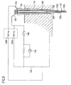
- Fig. 6 is a longitudinal section of a glow plug 101 for a diesel engine according to a second embodiment of the present invention.
- the glow plug 101 comprises the glow plug 1 mentioned above which is integrally combined with an ion sensor which detects an ion current to detect a condition of combustion of the engine.
- the glow plug 101 includes a ceramics heater 102 including a ceramics insulator 102a in which a heating element 102b is embedded. One end of the heating element 102b is connected to a negative pole lead wire 102c while the other end is connected to a positive pole lead wire 102d. To serve as an ion detecting electrode, the heating element 102b has a distal end 102ba which is exposed outside the ceramics insulator 102a.
- the negative pole lead wire 102c is taken out through the lateral side of the ceramics insulator 102a to be electrically connected to the inner surface of a sheath (metallic outer sleeve) 104 while the positive pole lead wire 102d is electrically connected to one end of an electrode fitting 106 inside the ceramics insulator 102a.
- the other end of the electrode fitting 106 is connected to an external connection terminal 108.
- the metallic outer sleeve 104 in which the ceramics heater 102 is secured has a greater overall length than a housing 110, and has an end 104e which is opposite from a distal end 104d in which the ceramics heater 102 is secured and which extends to the rear end of the housing 10 when the metallic outer sleeve is secured to the housing 110.
- the interior of the metallic outer sleeve 104 is filled with a refractory insulating powder 112, which is swaged to be densified, thus securing the external connection terminal 108 and insulating the external connection terminal 108 which is connected to the positive pole from the metallic outer sleeve 104 which is connected to the negative pole.
- the metallic outer sleeve 104 having the ceramics heater 102 secured in its one end 104d and having the external connection terminal 108 which extends toward the other end 104e is inserted into an internal bore 116 of the cylindrical housing 110 to be secured therein.
- An insulator 118 is inserted between the inner surface of the housing 110 at a location toward its distal end and the outer surface of the metallic outer sleeve 104 to provide an electrical insulation between the housing 110 and the metallic outer sleeve 104.
- the outer periphery of the housing 110 is subject to a swaging operation (indicated by character S in Fig. 6) to form an annular projection 110d on the inner periphery.
- the metallic outer sleeve 104 is secured within the housing 110 in the region S where the swaging operation has taken place.
- Steps to assemble the glow plug 101 which is integrally provided with the ion sensor will now be describe with reference to Figs. 6, 7 and 8.
- An assembly integrally including the ceramics heater 102, the electrode fitting 106 and the external connection terminal 108 which are carried within the metallic outer sleeve 104 is inserted into the distal end of the housing 110 (or the end located toward the ceramics heater 102) with threads 108a on the external connection terminal 108 placed first (see Fig. 7).
- a seal member 120 is fitted between the distal end of the housing 110 and the outer periphery of the metallic outer sleeve 104, and the refractory insulating powder 118 is filled into the housing 110 through a rear opening thereof, and a seal member 122 is fitted (see Fig. 8).
- the outer periphery of the housing is subject to a swaging operation in a region which is filled with the refractory insulating powder 118 to cause a plastic deformation of the housing 110, thus forming an annular projection 110d on its inner peripheral surface and densifying the refractory insulating powder 118 to secure the metallic outer sleeve 104 in place (a condition shown in Fig. 6).
- the metallic outer sleeve 104 which is electrically connected to the negative pole lead wire 102c of the ceramic house 102 is connected to a negative terminal 124 at the rear end of the housing 110 while the external connection terminal 108 which is electrically connected to the positive pole lead wire 102d through the electrode fitting 106 is connected to a positive terminal 126.
- An insulating ring 128 is interposed between the negative terminal 124 which is electrically connected to the metallic outer sleeve 104 and the housing 110, and an insulator 130 is interposed between the negative terminal 124 and the positive terminal 126 to provide an electrical insulation.
- the positive terminal 126 is connected to a positive pole of a battery 132 through a first relay 134A
- the negative terminal 124 is connected to the negative pole of the battery 132 through a second relay 134B.
- an electrical circuit for the glow plug is formed by the positive pole of the battery 132, the first relay 134A, the positive terminal 126, the external connection terminal 108, the electrode fitting 106, the positive pole lead wire 102d of the ceramics heater 102, the heating element 102b, the negative pole lead wire 102c, the metallic outer sleeve 104, the negative terminal 124, the second relay 134 and the negative pole of the battery 132.
- the housing 110 is secured to the cylinder head 136 of the engine, and the negative pole of the battery 132 is connected to the cylinder head 136 as the electrical ground.
- Current detecting means 138 and a sensor relay 140 are connected between the positive pole of the battery 132 and the positive terminal 126 of the glow plug 101. In this manner, an electrical circuit for the ion sensor is completed by the positive pole of the battery 132, the current detecting means 138, the sensor relay 140, the positive terminal 126, the external connection terminal 108, the electrode fitting 106, the heating element 102b which serves as an ion detecting electrode and the ground connection to the cylinder head 136.
- the first and the second relay 134A and 134B are turned on while the sensor relay 140 is turned off. There occurs a current flow through the electrical circuit for the glow plug, causing a heating of the heating element 102b to preheat the engine.
- the glow plug relays 134A and 134B are turned off while the ion sensor relay 140 is turned on.
- a voltage is generated between the heating element 102b of the ceramics heater 102 which functions as an ion detecting electrode and the cylinder head 136, causing ions within a combustion chamber which are generated during the combustion of the engine to produce a current flow through the sensor electrical circuit.
- the current detecting means 138 detects this current flow to provide a feedback control of the engine.
- the construction of the housing 110 is simplified in the similar manner as in the first embodiment, allowing the housing 110 to be manufactured inexpensively. Also, the distance L2 between the sheet surface 110a on the housing 110 which is to be disposed in abutment against the cylinder head 136 and the distal end of the ceramics heater 102 can be chosen as desired without requiring a modification in the configuration of the housing 110, allowing a significant cost-down.
- the insulator interposed between the housing 110 and the metallic outer sleeve 104 is not limited to the refractory insulating powder 118 which is densified by the swaging operation, but may comprise a resin or any other insulator.
Landscapes
- Engineering & Computer Science (AREA)
- Chemical & Material Sciences (AREA)
- Ceramic Engineering (AREA)
- Combustion & Propulsion (AREA)
- Mechanical Engineering (AREA)
- General Engineering & Computer Science (AREA)
- Resistance Heating (AREA)
Applications Claiming Priority (3)
| Application Number | Priority Date | Filing Date | Title |
|---|---|---|---|
| JP2001384690 | 2001-12-18 | ||
| JP2001384690A JP2003185137A (ja) | 2001-12-18 | 2001-12-18 | ディーゼルエンジン用グロープラグおよびその製造方法 |
| PCT/JP2002/011146 WO2003052323A1 (fr) | 2001-12-18 | 2002-10-28 | Bougie de prechauffage pour moteur diesel et procede de fabrication de ladite bougie de prechauffage |
Publications (1)
| Publication Number | Publication Date |
|---|---|
| EP1457736A1 true EP1457736A1 (fr) | 2004-09-15 |
Family
ID=19187746
Family Applications (1)
| Application Number | Title | Priority Date | Filing Date |
|---|---|---|---|
| EP02805013A Withdrawn EP1457736A1 (fr) | 2001-12-18 | 2002-10-28 | Bougie de prechauffage pour moteur diesel et procede de fabrication de ladite bougie de prechauffage |
Country Status (4)
| Country | Link |
|---|---|
| EP (1) | EP1457736A1 (fr) |
| JP (1) | JP2003185137A (fr) |
| CN (1) | CN1292196C (fr) |
| WO (1) | WO2003052323A1 (fr) |
Cited By (5)
| Publication number | Priority date | Publication date | Assignee | Title |
|---|---|---|---|---|
| DE102006016566A1 (de) * | 2005-09-22 | 2007-03-29 | Beru Ag | Zusammengesetzter Leiter, insbesondere für Glühkerzen für Dieselmotoren |
| US20150075473A1 (en) * | 2012-03-29 | 2015-03-19 | Ngk Spark Plug Co., Ltd. | Glow plug and method for manufacturing same |
| EP2698581A4 (fr) * | 2011-04-15 | 2015-12-23 | Ngk Spark Plug Co | Bougie à incandescence |
| WO2016050541A1 (fr) * | 2014-10-02 | 2016-04-07 | Robert Bosch Gmbh | Bougie-crayon de préchauffage |
| DE102007022619B4 (de) * | 2006-05-19 | 2018-11-08 | Ngk Spark Plug Co., Ltd. | Glühkerze und Verfahren zum Herstellen derselben |
Families Citing this family (6)
| Publication number | Priority date | Publication date | Assignee | Title |
|---|---|---|---|---|
| DE102005021229A1 (de) * | 2005-05-09 | 2006-11-16 | Robert Bosch Gmbh | Glühstiftkerze mit Brennraumdrucksensor |
| JP4843430B2 (ja) * | 2006-09-12 | 2011-12-21 | 日本特殊陶業株式会社 | グロープラグの製造方法 |
| EP2117280B1 (fr) * | 2007-02-22 | 2018-04-11 | Kyocera Corporation | Dispositif de chauffage en ceramique, bougie de prechauffage utilisant le dispositif de chauffage en ceramique, et procede de fabrication du dispositif de chauffage en ceramique |
| KR100915939B1 (ko) * | 2007-10-10 | 2009-09-11 | 주식회사 유라테크 | 글로우 플러그의 하우징 제조방법 |
| FR3021095B1 (fr) * | 2014-05-13 | 2016-06-10 | Bosch Gmbh Robert | Electrode de prechauffage et son procede de fabrication |
| JP2021021518A (ja) * | 2019-07-25 | 2021-02-18 | ボッシュ株式会社 | セラミックスヒータ型グロープラグおよびその製造方法 |
Family Cites Families (4)
| Publication number | Priority date | Publication date | Assignee | Title |
|---|---|---|---|---|
| JPS5740866U (fr) * | 1980-08-12 | 1982-03-05 | ||
| JPS5952726B2 (ja) * | 1981-06-24 | 1984-12-21 | 日本特殊陶業株式会社 | シ−ズ型グロ−プラグの取付金具にグロ−チュ−ブを接合する方法 |
| JP4092845B2 (ja) * | 1999-05-27 | 2008-05-28 | 株式会社デンソー | グロープラグおよびその製造方法 |
| JP2001108236A (ja) * | 1999-10-07 | 2001-04-20 | Ngk Spark Plug Co Ltd | シーズ封入型電子機器の製造方法 |
-
2001
- 2001-12-18 JP JP2001384690A patent/JP2003185137A/ja active Pending
-
2002
- 2002-10-28 WO PCT/JP2002/011146 patent/WO2003052323A1/fr not_active Ceased
- 2002-10-28 CN CN 02825546 patent/CN1292196C/zh not_active Expired - Fee Related
- 2002-10-28 EP EP02805013A patent/EP1457736A1/fr not_active Withdrawn
Non-Patent Citations (1)
| Title |
|---|
| See references of WO03052323A1 * |
Cited By (10)
| Publication number | Priority date | Publication date | Assignee | Title |
|---|---|---|---|---|
| DE102006016566A1 (de) * | 2005-09-22 | 2007-03-29 | Beru Ag | Zusammengesetzter Leiter, insbesondere für Glühkerzen für Dieselmotoren |
| DE102006016566B4 (de) * | 2005-09-22 | 2008-06-12 | Beru Ag | Zusammengesetzter Leiter, insbesondere für Glühkerzen für Dieselmotoren |
| US8569658B2 (en) | 2005-09-22 | 2013-10-29 | Beru Aktiengesellschaft | Composite conductor, in particular for glow plugs for diesel engines |
| DE102007022619B4 (de) * | 2006-05-19 | 2018-11-08 | Ngk Spark Plug Co., Ltd. | Glühkerze und Verfahren zum Herstellen derselben |
| EP2698581A4 (fr) * | 2011-04-15 | 2015-12-23 | Ngk Spark Plug Co | Bougie à incandescence |
| US9429322B2 (en) | 2011-04-15 | 2016-08-30 | Ngk Spark Plug Co., Ltd. | Glow plug |
| US20150075473A1 (en) * | 2012-03-29 | 2015-03-19 | Ngk Spark Plug Co., Ltd. | Glow plug and method for manufacturing same |
| EP2833069A4 (fr) * | 2012-03-29 | 2015-11-18 | Ngk Spark Plug Co | Bougie à incandescence et son procédé de fabrication |
| WO2016050541A1 (fr) * | 2014-10-02 | 2016-04-07 | Robert Bosch Gmbh | Bougie-crayon de préchauffage |
| JP2017527769A (ja) * | 2014-10-02 | 2017-09-21 | ローベルト ボッシュ ゲゼルシャフト ミット ベシュレンクテル ハフツング | グローピンプラグ |
Also Published As
| Publication number | Publication date |
|---|---|
| WO2003052323A1 (fr) | 2003-06-26 |
| CN1292196C (zh) | 2006-12-27 |
| JP2003185137A (ja) | 2003-07-03 |
| CN1606678A (zh) | 2005-04-13 |
Similar Documents
| Publication | Publication Date | Title |
|---|---|---|
| KR100427818B1 (ko) | 세라믹히터 | |
| EP1457736A1 (fr) | Bougie de prechauffage pour moteur diesel et procede de fabrication de ladite bougie de prechauffage | |
| JP2003130349A (ja) | グロープラグ | |
| JP3589206B2 (ja) | セラミックスヒータ型グロープラグおよびその製造方法。 | |
| US6727473B2 (en) | Ceramic heater device and method for manufacturing the device | |
| JP5485843B2 (ja) | グロープラグ及びその製造方法 | |
| JP2001141238A (ja) | ディーゼルエンジン用グロープラグおよびその製造方法 | |
| JP4175970B2 (ja) | グロープラグ | |
| EP1239222B2 (fr) | Dispositif chauffant céramique, et méthode de fabrication | |
| KR101656545B1 (ko) | 글로 플러그 및 그 제조방법 | |
| KR101673102B1 (ko) | 글로 플러그 | |
| JP2007247994A (ja) | セラミックグロープラグおよびセラミックグロープラグの製造方法 | |
| JP2002303424A (ja) | ディーゼルエンジン用グロープラグ | |
| JP4309757B2 (ja) | セラミックヒーター | |
| JP4310565B2 (ja) | セラミックヒータ型グロープラグおよびその製造方法 | |
| JP3873444B2 (ja) | グロープラグ及びその製造方法 | |
| JP2002206739A (ja) | セラミックスグロープラグおよびその製造方法 | |
| JP4295164B2 (ja) | グロープラグ | |
| JP2003139323A (ja) | ディーゼルエンジン用グロープラグおよびその製造方法 | |
| JP2001263664A (ja) | ディーゼルエンジン用グロープラグおよびその製造方法 | |
| JP2002195558A (ja) | セラミックスヒータ型グロープラグ | |
| JP2006038405A (ja) | グロープラグ | |
| JP6088897B2 (ja) | グロープラグ | |
| JP2013204938A (ja) | グロープラグ | |
| JP2002147758A (ja) | セラミックヒータ型グロープラグおよびその製造方法 |
Legal Events
| Date | Code | Title | Description |
|---|---|---|---|
| PUAI | Public reference made under article 153(3) epc to a published international application that has entered the european phase |
Free format text: ORIGINAL CODE: 0009012 |
|
| 17P | Request for examination filed |
Effective date: 20040318 |
|
| AK | Designated contracting states |
Kind code of ref document: A1 Designated state(s): AT BE BG CH CY CZ DE DK EE ES FI FR GB GR IE IT LI LU MC NL PT SE SK TR |
|
| STAA | Information on the status of an ep patent application or granted ep patent |
Free format text: STATUS: THE APPLICATION HAS BEEN WITHDRAWN |
|
| 18W | Application withdrawn |
Effective date: 20090226 |