EP1457737A2 - Chambre de combustion pour une turbine à gaz - Google Patents
Chambre de combustion pour une turbine à gaz Download PDFInfo
- Publication number
- EP1457737A2 EP1457737A2 EP04250318A EP04250318A EP1457737A2 EP 1457737 A2 EP1457737 A2 EP 1457737A2 EP 04250318 A EP04250318 A EP 04250318A EP 04250318 A EP04250318 A EP 04250318A EP 1457737 A2 EP1457737 A2 EP 1457737A2
- Authority
- EP
- European Patent Office
- Prior art keywords
- combustor
- chute
- flange
- wall
- attached
- Prior art date
- Legal status (The legal status is an assumption and is not a legal conclusion. Google has not performed a legal analysis and makes no representation as to the accuracy of the status listed.)
- Granted
Links
- 238000002485 combustion reaction Methods 0.000 claims abstract description 19
- 238000004519 manufacturing process Methods 0.000 claims description 4
- 238000000034 method Methods 0.000 claims description 4
- 239000000446 fuel Substances 0.000 description 10
- 239000012895 dilution Substances 0.000 description 5
- 238000010790 dilution Methods 0.000 description 5
- 238000003466 welding Methods 0.000 description 4
- 230000035515 penetration Effects 0.000 description 2
- 238000011144 upstream manufacturing Methods 0.000 description 2
- OKTJSMMVPCPJKN-UHFFFAOYSA-N Carbon Chemical compound [C] OKTJSMMVPCPJKN-UHFFFAOYSA-N 0.000 description 1
- 239000004215 Carbon black (E152) Substances 0.000 description 1
- 229910052799 carbon Inorganic materials 0.000 description 1
- 239000011203 carbon fibre reinforced carbon Substances 0.000 description 1
- 239000012141 concentrate Substances 0.000 description 1
- 238000010276 construction Methods 0.000 description 1
- 229930195733 hydrocarbon Natural products 0.000 description 1
- 150000002430 hydrocarbons Chemical class 0.000 description 1
- 238000002347 injection Methods 0.000 description 1
- 239000007924 injection Substances 0.000 description 1
- 239000000243 solution Substances 0.000 description 1
- 238000009834 vaporization Methods 0.000 description 1
Images
Classifications
-
- F—MECHANICAL ENGINEERING; LIGHTING; HEATING; WEAPONS; BLASTING
- F23—COMBUSTION APPARATUS; COMBUSTION PROCESSES
- F23R—GENERATING COMBUSTION PRODUCTS OF HIGH PRESSURE OR HIGH VELOCITY, e.g. GAS-TURBINE COMBUSTION CHAMBERS
- F23R3/00—Continuous combustion chambers using liquid or gaseous fuel
- F23R3/02—Continuous combustion chambers using liquid or gaseous fuel characterised by the air-flow or gas-flow configuration
- F23R3/04—Air inlet arrangements
- F23R3/045—Air inlet arrangements using pipes
-
- F—MECHANICAL ENGINEERING; LIGHTING; HEATING; WEAPONS; BLASTING
- F23—COMBUSTION APPARATUS; COMBUSTION PROCESSES
- F23R—GENERATING COMBUSTION PRODUCTS OF HIGH PRESSURE OR HIGH VELOCITY, e.g. GAS-TURBINE COMBUSTION CHAMBERS
- F23R2900/00—Special features of, or arrangements for continuous combustion chambers; Combustion processes therefor
- F23R2900/00005—Preventing fatigue failures or reducing mechanical stress in gas turbine components
Definitions
- the invention relates to a combustor for a gas turbine engine.
- the majority of the air entering a combustor enters at the upstream (front) end, usually close to the fuel injection points.
- the air mixes with and aids the vaporisation of the fuel, which then ignites and burns.
- the bulk motion of the combusting gas is from the front to the back of the combustor, exiting to the turbine.
- This simple air and fuel mixing method does not achieve complete combustion and may result in undesirable unburned carbon and hydrocarbon emissions as well as a non optimal turbine entry temperature profile.
- a commonly used solution to this situation is to pierce the combustor wall with a plurality of plain holes to provide extra, or 'dilution', air to complete the combustion process.
- the holes direct relatively small quantities of air into the combustor, usually perpendicular to the bulk flow, the momentum of the dilution air is much lower and therefore will have an insufficient penetration depth to be fully effective.
- An improvement can be obtained by employing air intake chutes in the holes to shield the dilution air from the main gas flow and help turn the air direction to a steep angle to the main flow.
- the air intake chute comprises a tubular section with a flange at one end.
- the flange has a greater diameter than the hole it is associated with and typically, is attached to the combustor by a number of welds around the flange edge.
- the location and lengths of the welds are chosen by the operator executing the weld. For practical reasons, such as visibility, especially during a manual welding operation, the weld size will vary in size and location on each air intake chute.
- a combustor for a gas turbine engine comprising a combustion chamber wall having formed therein at least one hole for admitting air into the combustion chamber; at least one air intake chute aligned with said hole; during operation a hoop stress field having regions of high and low stress concentration around said hole; wherein said chute is attached to the combustor wall in a region of low stress concentration.
- the chute is attached to the combustor wall in at least two regions of low stress concentration.
- the chute is provided with a flange disposed around one end thereof.
- At least one tab projects from the outer edge of said flange, and the at least one tab is attached to the combustor wall.
- a method of manufacturing a combustor as described in any of the preceding four paragraphs comprising the step of aligning the areas where the chute is attached to the combustor with the operational hoop stress field in the combustor wall.
- the areas where the chute is attached to the combustor wall are orientated such that they are in the same radial plane.
- a radial plane is taken to mean a plane perpendicular to the longitudinal axis of the engine and/or combustor.
- the invention is a combustor and a method of manufacturing the combustor, provided with air intake chutes which are aligned such that the areas where the chute is attached to the combustor wall are positioned away from the regions of concentrated hoop stress which are induced in the combustor walls during operation.
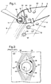
- Figure 1 is sectional view of a gas turbine engine combustor 2.
- the overall construction and operation of the engine is of a conventional kind, well known in the field, and will not be described in this specification beyond what is necessary to gain an understanding of the invention.
- the combustor 2 comprises an inner wall 4 and an outer wall 6, joined by a cowl 8 and a metering panel 10.
- a fuel injector 12 extends through the cowl 8 through a hole 14 where the fuel injector head 16 locates inside a sleeve 18 in the metering panel 10, leaving the end of the injector exposed to the combustion region.
- the injector head 16 comprises an aperture through which fuel will flow and air passages to allow air entry into the combustion region.
- chutes 24 Attached to the walls 4,6 and aligned with holes 22 are chutes 24. These may be cylindrical, the same diameter as hole 22 and have a scarfed end.
- the chutes 24 are provided with a flange 26 at one end which is of larger diameter than the holes 22.
- the flange 26, and hence the chute 24, is attached to the combustor wall 4,6 by some suitable attachment means.
- the flange 26 may, by way of non-limiting example, be welded to the combustor wall 4,6.
- pressurised high velocity air from the engine compressor (not shown) upstream of the combustor 2 is split into three flow paths as it reaches the combustor 2. Some of the air passes though the hole 14 around the fuel injector and through the air passages in the fuel injector head 16 into the combustion region. The majority of the remaining air passes either around the inside of the combustion chamber 2, constrained by the combustor inner (not shown), or passes around the outside of the combustion chamber 2, constrained by the combustor outer casing (not shown) before entering the combustion chamber through holes 20,22.
- the combustion process occupies the whole of the combustion chamber 2 but, expressed crudely, can be divided up into a core combustion region (of low air fuel ratio) immediately down stream of the metering panel 10 and a dilution region (of higher air fuel ratio) occupying approximately the latter two thirds of the combustion region before the gas exits the combustor 2 to the turbine (not shown). Holes 20,22 provide air for the dilution. Chutes 24 are required to achieve the required penetration to effectively dilute the combustion region.
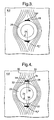
- chutes 24 are welded at a plurality of locations 28 around the circumference of the flange 26, as shown in Figure 2 (prior art).
- the hoop stress field is represented by lines 30 running circumferentially around the combustor wall 46. Hence point "B" and “C” marked on the centre line 30 are in the same radial plane.
- the present invention will reduce the propensity for weld cracks at the areas of attachment 28. It will be appreciated that cracks initiated at the areas of attachment 28 may propagate to the combustor wall 46, resulting in a critical failure of the combustor 2.
- Tabs 32 are provided such that they project outwardly from the flange 26.
- the tabs 32 are positioned on diametrically opposite sides of the flange 26 such that when attached to the combustor wall 4,6 they are in the same radial plane.
- the flange 26 is attached to the combustor wall 4,6 by welding means.
- the weld 34 is provided along the outermost edge 36 of the tab 32.
- the edge 36 may be flat or curved.
- edge 36 enables the weld operator to identify the beginning and end of the desired weld position. This embodiment offers the surprising advantage that the edge 36 provides a guide for the location and length of the weld during the weld operation.
- tabs 32 are chosen such that the weld 34 is positioned in the low stress regions "B" and "C". It will be appreciated that the tab 32 size will be different for different combustor configurations. However, by way of non limiting example, tab 32 projects up to about 0.14x (flange 26 diameter) and should have a length up to about 0.25x (flange 26 diameter).
- tab 32 may be attached to the combustor wall 4,6 by suitable attachment means other than welding.
Landscapes
- Engineering & Computer Science (AREA)
- Chemical & Material Sciences (AREA)
- Combustion & Propulsion (AREA)
- Mechanical Engineering (AREA)
- General Engineering & Computer Science (AREA)
- Pressure Welding/Diffusion-Bonding (AREA)
- Turbine Rotor Nozzle Sealing (AREA)
Applications Claiming Priority (2)
| Application Number | Priority Date | Filing Date | Title |
|---|---|---|---|
| GB0305868 | 2003-03-14 | ||
| GB0305868A GB2399408B (en) | 2003-03-14 | 2003-03-14 | Gas turbine engine combustor |
Publications (3)
| Publication Number | Publication Date |
|---|---|
| EP1457737A2 true EP1457737A2 (fr) | 2004-09-15 |
| EP1457737A3 EP1457737A3 (fr) | 2009-08-12 |
| EP1457737B1 EP1457737B1 (fr) | 2015-04-01 |
Family
ID=9954778
Family Applications (1)
| Application Number | Title | Priority Date | Filing Date |
|---|---|---|---|
| EP04250318.5A Expired - Lifetime EP1457737B1 (fr) | 2003-03-14 | 2004-01-22 | Chambre de combustion pour une turbine à gaz |
Country Status (3)
| Country | Link |
|---|---|
| US (1) | US7121096B2 (fr) |
| EP (1) | EP1457737B1 (fr) |
| GB (1) | GB2399408B (fr) |
Families Citing this family (5)
| Publication number | Priority date | Publication date | Assignee | Title |
|---|---|---|---|---|
| EP2957833B1 (fr) | 2014-06-17 | 2018-10-24 | Rolls-Royce Corporation | Ensemble chambre de combustion avec des goulottes |
| CN105673485B (zh) * | 2016-01-15 | 2017-09-19 | 沈阳天朗艾尔压缩机有限公司 | 一种滑片式空气压缩机 |
| US20200041127A1 (en) * | 2018-08-01 | 2020-02-06 | General Electric Company | Dilution Structure for Gas Turbine Engine Combustor |
| US11248789B2 (en) | 2018-12-07 | 2022-02-15 | Raytheon Technologies Corporation | Gas turbine engine with integral combustion liner and turbine nozzle |
| KR102164620B1 (ko) * | 2019-06-19 | 2020-10-12 | 두산중공업 주식회사 | 연소기 및 이를 포함하는 가스터빈 |
Citations (1)
| Publication number | Priority date | Publication date | Assignee | Title |
|---|---|---|---|---|
| US3899882A (en) | 1974-03-27 | 1975-08-19 | Westinghouse Electric Corp | Gas turbine combustor basket cooling |
Family Cites Families (13)
| Publication number | Priority date | Publication date | Assignee | Title |
|---|---|---|---|---|
| US4392355A (en) * | 1969-11-13 | 1983-07-12 | General Motors Corporation | Combustion liner |
| US3886735A (en) * | 1974-04-01 | 1975-06-03 | Gen Motors Corp | Ceramic combustion liner |
| GB2003989A (en) * | 1977-09-09 | 1979-03-21 | Westinghouse Electric Corp | Cooled air inlet tube for a gas turbine combustor |
| US4343355A (en) * | 1980-01-14 | 1982-08-10 | Caterpillar Tractor Co. | Low stress heat exchanger and method of making the same |
| US4700544A (en) * | 1985-01-07 | 1987-10-20 | United Technologies Corporation | Combustors |
| US4875339A (en) * | 1987-11-27 | 1989-10-24 | General Electric Company | Combustion chamber liner insert |
| US5189279A (en) * | 1991-12-30 | 1993-02-23 | General Electric Company | Steam turbine rotor welding |
| FR2686683B1 (fr) * | 1992-01-28 | 1994-04-01 | Snecma | Turbomachine a chambre de combustion demontable. |
| FR2714152B1 (fr) * | 1993-12-22 | 1996-01-19 | Snecma | Dispositif de fixation d'une tuile de protection thermique dans une chambre de combustion. |
| US5454221A (en) * | 1994-03-14 | 1995-10-03 | General Electric Company | Dilution flow sleeve for reducing emissions in a gas turbine combustor |
| FR2826102B1 (fr) * | 2001-06-19 | 2004-01-02 | Snecma Moteurs | Perfectionnements apportes aux chambres de combustion de turbine a gaz |
| GB2379499B (en) * | 2001-09-11 | 2004-01-28 | Rolls Royce Plc | Gas turbine engine combustor |
| US6681577B2 (en) * | 2002-01-16 | 2004-01-27 | General Electric Company | Method and apparatus for relieving stress in a combustion case in a gas turbine engine |
-
2003
- 2003-03-14 GB GB0305868A patent/GB2399408B/en not_active Expired - Fee Related
-
2004
- 2004-01-22 EP EP04250318.5A patent/EP1457737B1/fr not_active Expired - Lifetime
- 2004-02-03 US US10/769,780 patent/US7121096B2/en not_active Expired - Lifetime
Patent Citations (1)
| Publication number | Priority date | Publication date | Assignee | Title |
|---|---|---|---|---|
| US3899882A (en) | 1974-03-27 | 1975-08-19 | Westinghouse Electric Corp | Gas turbine combustor basket cooling |
Also Published As
| Publication number | Publication date |
|---|---|
| GB2399408B (en) | 2006-02-22 |
| GB0305868D0 (en) | 2003-04-16 |
| US20040231336A1 (en) | 2004-11-25 |
| EP1457737B1 (fr) | 2015-04-01 |
| GB2399408A (en) | 2004-09-15 |
| EP1457737A3 (fr) | 2009-08-12 |
| US7121096B2 (en) | 2006-10-17 |
Similar Documents
| Publication | Publication Date | Title |
|---|---|---|
| JP5374031B2 (ja) | タービンエンジンにおけるNOxエミッションを低減するのを可能にするための装置及びガスタービンエンジン | |
| CN100520185C (zh) | 具有自由浮动旋流器的燃气涡轮发动机的燃烧器拱顶组件 | |
| US7707835B2 (en) | Axial flow sleeve for a turbine combustor and methods of introducing flow sleeve air | |
| JP4902208B2 (ja) | 燃焼器用ベンチュリ | |
| JP5468812B2 (ja) | 燃焼器組立体及び、ガスタービンエンジン用の燃料ノズル | |
| JP5132194B2 (ja) | 第1段ノズルからの二次燃料噴射にかかるシステム及び方法 | |
| US8033114B2 (en) | Multimode fuel injector for combustion chambers, in particular of a jet engine | |
| EP1558875B1 (fr) | Chemise de chambre de combustion de turbine a cavite d'ecoulement vortex guide | |
| US8261556B2 (en) | Device for guiding an element in an orifice in a wall of a turbomachine combustion chamber | |
| CA2603619C (fr) | Tubulure de carburant interne et raccord d'admission de carburant | |
| US20110203287A1 (en) | Combustor liner for a turbine engine | |
| US20120015309A1 (en) | Method for a combustor nozzle | |
| US8261554B2 (en) | Fuel nozzle tip assembly | |
| US20100058767A1 (en) | Swirl angle of secondary fuel nozzle for turbomachine combustor | |
| JPH0788947B2 (ja) | ガスタービン機関の環状燃焼器及びその運転方法 | |
| US20190353351A1 (en) | Assembly for a turbomachine combustion chamber | |
| US10914237B2 (en) | Airblast injector for a gas turbine engine | |
| CN115200040B (zh) | 用于燃气涡轮发动机燃烧器的稀释喇叭对 | |
| EP1457737B1 (fr) | Chambre de combustion pour une turbine à gaz | |
| JP3974595B2 (ja) | タービンエンジンのオグメンタおよびその運転方法 | |
| WO2017169950A1 (fr) | Chambre de combustion de turbine à gaz | |
| CN1573067A (zh) | 增强器的带导向的喷管 | |
| US20120047895A1 (en) | Systems and apparatus relating to combustor cooling and operation in gas turbine engines | |
| EP2584267B1 (fr) | Injecteur à plusieurs tubes à combustible | |
| JP4031774B2 (ja) | ガスタービン用燃焼器 |
Legal Events
| Date | Code | Title | Description |
|---|---|---|---|
| PUAI | Public reference made under article 153(3) epc to a published international application that has entered the european phase |
Free format text: ORIGINAL CODE: 0009012 |
|
| AK | Designated contracting states |
Kind code of ref document: A2 Designated state(s): AT BE BG CH CY CZ DE DK EE ES FI FR GB GR HU IE IT LI LU MC NL PT RO SE SI SK TR |
|
| AX | Request for extension of the european patent |
Extension state: AL LT LV MK |
|
| PUAL | Search report despatched |
Free format text: ORIGINAL CODE: 0009013 |
|
| AK | Designated contracting states |
Kind code of ref document: A3 Designated state(s): AT BE BG CH CY CZ DE DK EE ES FI FR GB GR HU IE IT LI LU MC NL PT RO SE SI SK TR |
|
| AX | Request for extension of the european patent |
Extension state: AL LT LV MK |
|
| 17P | Request for examination filed |
Effective date: 20090814 |
|
| AKX | Designation fees paid |
Designated state(s): DE FR |
|
| 17Q | First examination report despatched |
Effective date: 20110315 |
|
| GRAP | Despatch of communication of intention to grant a patent |
Free format text: ORIGINAL CODE: EPIDOSNIGR1 |
|
| GRAS | Grant fee paid |
Free format text: ORIGINAL CODE: EPIDOSNIGR3 |
|
| INTG | Intention to grant announced |
Effective date: 20150116 |
|
| GRAA | (expected) grant |
Free format text: ORIGINAL CODE: 0009210 |
|
| AK | Designated contracting states |
Kind code of ref document: B1 Designated state(s): DE FR |
|
| REG | Reference to a national code |
Ref country code: DE Ref legal event code: R096 Ref document number: 602004046891 Country of ref document: DE Effective date: 20150521 |
|
| RAP2 | Party data changed (patent owner data changed or rights of a patent transferred) |
Owner name: ROLLS-ROYCE PLC |
|
| REG | Reference to a national code |
Ref country code: DE Ref legal event code: R097 Ref document number: 602004046891 Country of ref document: DE |
|
| REG | Reference to a national code |
Ref country code: FR Ref legal event code: PLFP Year of fee payment: 13 |
|
| PLBE | No opposition filed within time limit |
Free format text: ORIGINAL CODE: 0009261 |
|
| STAA | Information on the status of an ep patent application or granted ep patent |
Free format text: STATUS: NO OPPOSITION FILED WITHIN TIME LIMIT |
|
| 26N | No opposition filed |
Effective date: 20160105 |
|
| REG | Reference to a national code |
Ref country code: DE Ref legal event code: R082 Ref document number: 602004046891 Country of ref document: DE Representative=s name: HERNANDEZ, YORCK, DIPL.-ING., DE |
|
| REG | Reference to a national code |
Ref country code: FR Ref legal event code: PLFP Year of fee payment: 14 |
|
| REG | Reference to a national code |
Ref country code: FR Ref legal event code: PLFP Year of fee payment: 15 |
|
| PGFP | Annual fee paid to national office [announced via postgrant information from national office to epo] |
Ref country code: DE Payment date: 20180129 Year of fee payment: 15 |
|
| PGFP | Annual fee paid to national office [announced via postgrant information from national office to epo] |
Ref country code: FR Payment date: 20180125 Year of fee payment: 15 |
|
| REG | Reference to a national code |
Ref country code: DE Ref legal event code: R119 Ref document number: 602004046891 Country of ref document: DE |
|
| PG25 | Lapsed in a contracting state [announced via postgrant information from national office to epo] |
Ref country code: DE Free format text: LAPSE BECAUSE OF NON-PAYMENT OF DUE FEES Effective date: 20190801 Ref country code: FR Free format text: LAPSE BECAUSE OF NON-PAYMENT OF DUE FEES Effective date: 20190131 |