EP1457775B1 - Schlauch aus hochtemperaturbeständigem Kunststoff, Verfahren zur Gestaltung des Endes eines solchen Schlauches - Google Patents
Schlauch aus hochtemperaturbeständigem Kunststoff, Verfahren zur Gestaltung des Endes eines solchen Schlauches Download PDFInfo
- Publication number
- EP1457775B1 EP1457775B1 EP04405125A EP04405125A EP1457775B1 EP 1457775 B1 EP1457775 B1 EP 1457775B1 EP 04405125 A EP04405125 A EP 04405125A EP 04405125 A EP04405125 A EP 04405125A EP 1457775 B1 EP1457775 B1 EP 1457775B1
- Authority
- EP
- European Patent Office
- Prior art keywords
- hose
- wall
- peek
- plastic
- tube
- Prior art date
- Legal status (The legal status is an assumption and is not a legal conclusion. Google has not performed a legal analysis and makes no representation as to the accuracy of the status listed.)
- Expired - Lifetime
Links
- 239000004033 plastic Substances 0.000 title claims abstract description 34
- 239000000463 material Substances 0.000 title claims abstract description 24
- 238000000034 method Methods 0.000 title claims abstract description 10
- 239000004696 Poly ether ether ketone Substances 0.000 claims abstract description 30
- 229920002530 polyetherether ketone Polymers 0.000 claims abstract description 30
- 239000011521 glass Substances 0.000 claims abstract description 28
- 229920006260 polyaryletherketone Polymers 0.000 claims abstract description 15
- JUPQTSLXMOCDHR-UHFFFAOYSA-N benzene-1,4-diol;bis(4-fluorophenyl)methanone Chemical compound OC1=CC=C(O)C=C1.C1=CC(F)=CC=C1C(=O)C1=CC=C(F)C=C1 JUPQTSLXMOCDHR-UHFFFAOYSA-N 0.000 claims description 24
- 238000002347 injection Methods 0.000 claims description 3
- 239000007924 injection Substances 0.000 claims description 3
- 229920001657 poly(etheretherketoneketone) Polymers 0.000 claims 4
- 238000000465 moulding Methods 0.000 claims 1
- 238000005266 casting Methods 0.000 abstract description 4
- 238000001746 injection moulding Methods 0.000 abstract description 4
- 150000002576 ketones Chemical class 0.000 abstract 1
- 230000008719 thickening Effects 0.000 description 30
- 238000001816 cooling Methods 0.000 description 5
- 238000005538 encapsulation Methods 0.000 description 4
- 239000007788 liquid Substances 0.000 description 2
- 239000006223 plastic coating Substances 0.000 description 2
- 239000000243 solution Substances 0.000 description 2
- XLYOFNOQVPJJNP-UHFFFAOYSA-N water Substances O XLYOFNOQVPJJNP-UHFFFAOYSA-N 0.000 description 2
- RNFJDJUURJAICM-UHFFFAOYSA-N 2,2,4,4,6,6-hexaphenoxy-1,3,5-triaza-2$l^{5},4$l^{5},6$l^{5}-triphosphacyclohexa-1,3,5-triene Chemical compound N=1P(OC=2C=CC=CC=2)(OC=2C=CC=CC=2)=NP(OC=2C=CC=CC=2)(OC=2C=CC=CC=2)=NP=1(OC=1C=CC=CC=1)OC1=CC=CC=C1 RNFJDJUURJAICM-UHFFFAOYSA-N 0.000 description 1
- 239000004642 Polyimide Substances 0.000 description 1
- 239000011248 coating agent Substances 0.000 description 1
- 238000000576 coating method Methods 0.000 description 1
- 150000001875 compounds Chemical class 0.000 description 1
- 238000007765 extrusion coating Methods 0.000 description 1
- 230000002349 favourable effect Effects 0.000 description 1
- 239000003063 flame retardant Substances 0.000 description 1
- 238000010438 heat treatment Methods 0.000 description 1
- 239000000155 melt Substances 0.000 description 1
- 238000002844 melting Methods 0.000 description 1
- 230000008018 melting Effects 0.000 description 1
- 239000002184 metal Substances 0.000 description 1
- 230000002093 peripheral effect Effects 0.000 description 1
- 229920001721 polyimide Polymers 0.000 description 1
- 238000006116 polymerization reaction Methods 0.000 description 1
- 230000005855 radiation Effects 0.000 description 1
- 239000000779 smoke Substances 0.000 description 1
- 239000000126 substance Substances 0.000 description 1
Images


Classifications
-
- B—PERFORMING OPERATIONS; TRANSPORTING
- B01—PHYSICAL OR CHEMICAL PROCESSES OR APPARATUS IN GENERAL
- B01L—CHEMICAL OR PHYSICAL LABORATORY APPARATUS FOR GENERAL USE
- B01L3/00—Containers or dishes for laboratory use, e.g. laboratory glassware; Droppers
- B01L3/56—Labware specially adapted for transferring fluids
- B01L3/565—Seals
-
- F—MECHANICAL ENGINEERING; LIGHTING; HEATING; WEAPONS; BLASTING
- F16—ENGINEERING ELEMENTS AND UNITS; GENERAL MEASURES FOR PRODUCING AND MAINTAINING EFFECTIVE FUNCTIONING OF MACHINES OR INSTALLATIONS; THERMAL INSULATION IN GENERAL
- F16L—PIPES; JOINTS OR FITTINGS FOR PIPES; SUPPORTS FOR PIPES, CABLES OR PROTECTIVE TUBING; MEANS FOR THERMAL INSULATION IN GENERAL
- F16L11/00—Hoses, i.e. flexible pipes
- F16L11/04—Hoses, i.e. flexible pipes made of rubber or flexible plastics
- F16L11/12—Hoses, i.e. flexible pipes made of rubber or flexible plastics with arrangements for particular purposes, e.g. specially profiled, with protecting layer, heated, electrically conducting
- F16L11/122—Hoses provided with integrated fixing means, e.g. hooks
-
- F—MECHANICAL ENGINEERING; LIGHTING; HEATING; WEAPONS; BLASTING
- F16—ENGINEERING ELEMENTS AND UNITS; GENERAL MEASURES FOR PRODUCING AND MAINTAINING EFFECTIVE FUNCTIONING OF MACHINES OR INSTALLATIONS; THERMAL INSULATION IN GENERAL
- F16L—PIPES; JOINTS OR FITTINGS FOR PIPES; SUPPORTS FOR PIPES, CABLES OR PROTECTIVE TUBING; MEANS FOR THERMAL INSULATION IN GENERAL
- F16L33/00—Arrangements for connecting hoses to rigid members; Rigid hose-connectors, i.e. single members engaging both hoses
- F16L33/28—Arrangements for connecting hoses to rigid members; Rigid hose-connectors, i.e. single members engaging both hoses for hoses with one end terminating in a radial flange or collar
-
- B—PERFORMING OPERATIONS; TRANSPORTING
- B01—PHYSICAL OR CHEMICAL PROCESSES OR APPARATUS IN GENERAL
- B01L—CHEMICAL OR PHYSICAL LABORATORY APPARATUS FOR GENERAL USE
- B01L3/00—Containers or dishes for laboratory use, e.g. laboratory glassware; Droppers
- B01L3/50—Containers for the purpose of retaining a material to be analysed, e.g. test tubes
- B01L3/502—Containers for the purpose of retaining a material to be analysed, e.g. test tubes with fluid transport, e.g. in multi-compartment structures
- B01L3/5027—Containers for the purpose of retaining a material to be analysed, e.g. test tubes with fluid transport, e.g. in multi-compartment structures by integrated microfluidic structures, i.e. dimensions of channels and chambers are such that surface tension forces are important, e.g. lab-on-a-chip
-
- G—PHYSICS
- G01—MEASURING; TESTING
- G01N—INVESTIGATING OR ANALYSING MATERIALS BY DETERMINING THEIR CHEMICAL OR PHYSICAL PROPERTIES
- G01N30/00—Investigating or analysing materials by separation into components using adsorption, absorption or similar phenomena or using ion-exchange, e.g. chromatography or field flow fractionation
- G01N30/02—Column chromatography
- G01N30/60—Construction of the column
- G01N30/6004—Construction of the column end pieces
Definitions
- the invention relates to a plastic tube with a tubular wall made of a highly temperature-resistant plastic, namely PEEK, PAEK or PEEKK.
- the invention further relates to a method for forming a connection head on a plastic tube having a wall made of a high temperature resistant plastic, namely PEEK, PAEK or PEEKK.
- PEEK tubes have come into use recently, which are also called PEEK tubes.
- the material of these hoses or tubes is polyaryletheretherketone (Other sources indicate polyetheretherketone).
- Related materials are polyaryletherketone (PAEK) and polyetheretherketoneketone (PEEKK). These materials are resistant to high temperatures and are largely resistant to the influence of chemicals and radiation. They are flame retardant and have a very low smoke development in the fire. They have a favorable sliding behavior and wear behavior. At temperatures above 334 ° C they are thermoplastically processable.
- Such tubes or tubes are also commercially available with a glass capillary inside.
- EP 0 698 789 A1 discloses a polyimide-coated glass capillary onto which a coating of PEEK is sprayed. This encapsulation forms a jacket around an end region of the capillary and has a thickening.
- the US 5,188,730 A shows a capillary made of PEEK or metal, the end of which is equipped with a clamping ring.
- the material of this clamping ring is not specified. How this clamping ring is attached to the capillary, is not executed in the Scriptures.
- US 6,149,996 A shows a plastic tube according to the preamble of claim 1 and a method according to the preamble of claim 9.
- connection head for connecting the plastic hose to a connection head of a hose end, pipe end or device has a thickening of the wall of PEEK, PAEK or PEEK, which thickening is formed by an injection molding process. This thickening can be formed with an end surface which is close to a corresponding end face of a suitable connection head can be pressed.
- the contact pressure is advantageously achieved via a screw-fitting.
- the object is achieved in that a thickening of the wall of PEEK, PAEK or PEEK is formed by injection molding.
- the overmolding of the plastic tube with a material with similar temperature behavior and similar structure allows a connection of the material of the wall with the material of the thickening.
- the material of the wall is softened by the hot material sprayed around the wall into a mold for thickening. Due to the achieved cohesion between hose and extrusion coating, it is assumed that a molecular connection of the material of the wall with the injected material is established.
- the inner diameter of the plastic tube is unchanged after attaching the thickening, the inner diameter is advantageously secured by a glass capillary or by a mandrel of the mold.
- Advantageous inner diameters of the glass capillary or the tube are less than 0.5 mm.
- the inner diameter is less than 0.3 mm, more preferably less than 0.2. Due to the design of a connection head on the plastic tubing, it is practically possible to achieve a dead-water corner minimized connection even with such tiny cross-sections.
- glass capillaries are advantageously present in the plastic tubing. These Glass capillary advantageously has an inner diameter of at most 0.2 mm, preferably of at most 0.1, particularly preferably of at most 0.05 mm.
- the thickening of the hose wall consists of PEEK, PAEK or PEEKK. Particularly preferably, the hose wall and the thickening of the same plastic. It is essential that the material of the thickening and the material of the hose wall have similar melting points and connect with each other during encapsulation of the hose wall.
- the thickening is formed on the outside of the hose wall.
- the hose end can be present at a casting wall or be set back relative to this on a mandrel of the casting mold.
- the heat of the injected material melts the surface of the wall and combines with the injected liquid plastic.
- the materials of the tube wall and the thickening of the tube wall are then advantageously molecularly connected. As a result, no connection surface is no longer available, but thickening and hose wall are virtually one piece.
- the outer diameter of the thickening is formed concentrically to the inner diameter, a mandrel is advantageously provided on the mold, which is inserted during the injection molding in the opening of the tube. Therefore, this mandrel aligns the inner diameter concentric with the injection mold. As a result, the connection head can be exactly concentric with the inner diameter.
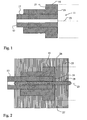
- connection head 11 shown in Figure 1 at the end of a PEEK tube 13 forms a thickening 15 of the wall 17 of the tube 13.
- the material of the thickening 15 and the wall 17 is the same. Contrary to the representation, therefore, at the junction between the wall 17 and thickening 15 in reality no clear dividing line can be seen.
- the material of the thickening and the wall are molecularly connected. So that this connection can take place over a larger area, the outer surface of the tube 13 can also be grooved.
- the thickening 15 has an end region with a larger outer diameter and a region further away from the end of the tube with a smaller outer diameter. In this way, a collar 19 is formed, which can be pressed with a fitting against a contact surface.
- the end face 21 of the connection head 11 is planar and perpendicular to the axis 23 of the tube.
- the axis 23 of the tube 13 is assumed to be centric to the inner diameter of the tube.
- the outer diameter of the thickening 15 is formed concentrically to the axis of the tube.
- FIG. 2 shows a connection head 11 according to FIG. 1 in the mold 25.
- the mold 25 has two or more peripheral partial molds 26, 27 and a central mandrel 29.
- the diameter of the mandrel 29 is matched to the inner diameter of the tube 13. It is inserted into the tube 13 and thus ensures the dimensional accuracy of the inner diameter. By pouring the tube 13, this is softened and partially liquefied. When cooling the thickening 15, the plastic contracts. This results in a change in length of the connection head 11. Since the wall 17 of the tube 13 is connected to the thickening, the tube also contracts in length, as far as it is surrounded by the thickening.
- the material of the thickening is the same as the material of the pipe wall 17, it is not significant whether the pipe reaches to the end face 21 of the connection head 11 or not.
- the tube 13 only has to project into the mold by a certain length. A distance between the end of the tube and the end surface is filled up by the encapsulation and thus supplemented. The length over which the encapsulation and the pipe wall extend together must guarantee that a sufficient connection with the material of the thickening arises. Since a subsequent compound, even if it is molecular, not the has the same properties as they are achieved by a continuous polymerization, a sufficiently large surface must be offered.
- connection head 11 Since the mandrel 29 is arranged centrally in the casting mold, the outer shape of the connection head 11 is arranged centrically to the inner diameter of the tube. This centricity guarantees a very precise, axial alignment of two connection heads to each other and thereby also the inner diameter of the adjoining parts to each other.
- a connection head with a shortened glass capillary is shown in FIG.
- the thickening is aligned with the inner diameter of the PEEK tube. As a result, irregularities in the wall thickness of the tubes can be compensated. This allows a very precise, virtually dead water corner-free connection between two connection heads 11th
- connection head of a PEEK tube 13 is connected to a micro-pipetting needle 33.
- the pipetting needle 33 has a tube whose inner diameter corresponds to the inner diameter of the PEEK tube 13.
- the connection heads 11 and 35 of PEEK tubes 13 and pipetting needle 33 have cooperating fitting parts 37 and 19 which ensure centering of the inner diameters on one another.
- an internal thread is formed, in which a fitting 39 is screwed.
- the fitting is from the outside of the thickening 15 and presses against the collar 19.
- the fitting 39 is rotatable about the thickening 15, so that the connection head 11 when screwing the connection heads against each other need not be rotated.
Landscapes
- Engineering & Computer Science (AREA)
- General Engineering & Computer Science (AREA)
- Mechanical Engineering (AREA)
- Health & Medical Sciences (AREA)
- Clinical Laboratory Science (AREA)
- Chemical & Material Sciences (AREA)
- Chemical Kinetics & Catalysis (AREA)
- Injection Moulding Of Plastics Or The Like (AREA)
- Laminated Bodies (AREA)
- Shaping Of Tube Ends By Bending Or Straightening (AREA)
Description
- Die Erfindung betrifft einen Kunststoffschlauch mit einer rohrförmigen Wandung aus einem hochtemteraturbeständigen Kunststoff, namentlich aus PEEK, PAEK oder PEEKK. Die Erfindung betrifft weiter ein Verfahren zur Ausbildung eines Anschlusskopfes an einem Kunststoffschlauch mit einer Wandung aus einem hochtemperaturfesten Kunststoff, namentlich aus PEEK, PAEK oder PEEKK.
- Im Laborbereich werden kleinste Mengen von Flüssigkeiten pipetiert und in Schläuchen und Rohren transportiert. Dazu sind in jüngster Zeit PEEK-Schläuche in Gebrauch gekommen, welche auch PEEK-Röhrchen genannt werden. Das Material dieser Schläuche oder Röhrchen ist Polyaryletheretherketon (Andere Quellen geben Polyetheretherketon an). Verwandte Materialien dazu sind Polyaryletherketon (PAEK) und Polyetheretherketonketon (PEEKK). Diese Materialien sind hochtemperaturbeständig und weitgehend resistent gegen den Einfluss von Chemikalien und Strahlen. Sie sind schwer entflammbar und weisen im Brand eine sehr geringe Rauchentwicklung auf. Sie besitzen ein günstiges Gleitverhalten und Verschleissverhalten. Bei Temperaturen über 334°C sind sie thermoplastisch verarbeitbar.
- Solche Röhrchen oder Schläuche gibt es im Handel auch mit einer Glaskapillare darin.
- Die EP 0 698 789A1 offenbart eine mit Polyimid beschichtete Glaskapillare, auf welche ein Überzug aus PEEK aufgespritzt ist. Diese Umspritzung bildet einen Mantel um einen Endbereich der Kapillare und besitzt eine Verdickung.
- Die US 5,188,730 A zeigt eine Kapillare aus PEEK oder Metall, deren Ende mit einem Klemmring bestückt ist. Das Material dieses Klemmrings ist nicht spezifiziert. Wie dieser Klemmring an der Kapillare befestigt wird, ist in der Schrift nicht ausgeführt.
- Ferner zeigt die US 6,149,996 A einen Kunststoffschlauches nach dem Oberbegriff von Anspruch 1 bzw. ein Verfahren nach dem Oberbegriff von Anspruch 9.
- Es ist die Aufgabe der Erfindung, eine Lösung für den Anschluss eines solchen Röhrchens oder Schlauches an ein zweites Röhrchen, an einen Schlauch oder an ein Gerät vorzuschlagen.
- Erfindungsgemäss wird die Lösung dieser Aufgabe bei einem Schlauch gemäss Anspruch 1 durch die kennzeichnenden Merkmale erreicht. Der Anschlusskopf zum Anschliessen des Kunststoffschlauches an einen Anschlusskopf eines Schlauch-Endes, Rohr-Endes oder Geräts, weist eine Verdickung der Wandung aus PEEK, PAEK oder PEEK auf, welche Verdickung durch ein Spritzgussverfahren angeformt ist. Diese Verdickung lässt sich mit einer Endfläche ausbilden, welche dicht an eine entsprechende Endfläche eines passenden Anschlusskopfes gepresst werden kann. Die Anpressung wird vorteilhaft über ein schraubbares Fitting erreicht.
- Bei einem Verfahren gemäss dem Oberbegriff des unabhängigen Verfahrensanspruchs 9 wird die Aufgabe dadurch gelöst, dass eine Verdickung der Wandung aus PEEK, PAEK oder PEEK mittels Spritzgiessen angeformt wird. Das Umspritzen des Kunststoffröhrchens mit einem Material mit ähnlichem Temperaturverhalten und ähnlicher Struktur erlaubt eine Verbindung des Materials der Wandung mit dem Material der Verdickung. Das Material der Wandung wird vom heiss um die Wandung in eine Form gespritzten Material für die Verdickung aufgeweicht. Aufgrund des erreichten Zusammenhalts zwischen Schlauch und Umspritzung wird angenommen, dass sich eine molekulare Verbindung des Materials der Wandung mit dem eingespritzten Material einstellt.
- Damit der Innendurchmesser des Kunststoffschlauches nach dem Anbringen der Verdickung unverändert ist, ist der Innendurchmesser vorteilhaft durch eine Glaskapillare oder durch einen Dorn der Gussform gesichert.
- Vorteilhaft ist daher eine Glaskapillare ummantelt vom Schlauch. Die Glaskapillare kann einen Innendurchmesser von bis zu 0.05 mm aufweisen. Diese Glaskapillare erfährt, im Gegensatz zur Kunststoffummantelung, keine Längenveränderung durch die Erwärmung und Abkühlung beim Anbringen der Verdickung. Die Wandung des Kunststoffschlauches hingegen zieht sich beim Auskühlen zusammen. Daher übersteht die anfänglich fluchtend abgelängte Glaskapillare nach dem Anbringen des Anschlusskopfes ihren Kunststoffmantel in Längsrichtung um einen Minimalbetrag. Diese Länge der Glaskapillare kann anschliessend an die Ausbildung des Anschlusskopfes vorteilhaft fluchtend und ebenflächig mit einer Endfläche des Anschlusskopfes abgelängt werden.
- Vorteilhafte Innendurchmesser der Glaskapillare oder des Schlauches sind kleiner als 0.5 mm. Bevorzugt ist der Innendurchmesser kleiner als 0.3 mm, besonders bevorzugt kleiner als 0.2. Durch die Ausbildung eines Anschlusskopfes am Kunststoffschlauch ist auch bei so winzigen Querschnitten praktisch eine totwassereckenminimierte Verbindung möglich. Für kleinere Innendurchmesser sind vorteilhaft Glaskapillaren im Kunststoffschlauch vorhanden. Diese Glaskapillare weist vorteilhaft einen Innendurchmesser auf von höchstens 0.2 mm, bevorzugt von höchstens 0.1, besonders bevorzugt von höchstens 0.05mm.
- Die Verdickung der Schlauchwandung besteht aus PEEK, PAEK oder PEEKK. Besonders bevorzugt sind die Schlauchwandung und die Verdickung aus dem selben Kunststoff. Wesentlich ist dabei, dass das Material der Verdickung und das Material der Schlauchwandung ähnliche Schmelzpunkte aufweisen und beim Umspritzen der Schlauchwandung sich miteinander verbinden.
- Damit die Verbindung über eine möglichst grosse Fläche stattfinden kann, ist die Verdickung auf der Aussenseite der Schlauchwandung ausgebildet. Das Schlauchende kann dabei an einer Gussformwandung anstehen oder gegenüber dieser auf einem Dorn der Gussform zurückgesetzt sein. Durch die Hitze des eingespritzten Materials schmilzt die Oberfläche der Wandung und verbindet sich mit dem eingespritzten flüssigen Kunststoff. Die Materialien der Schlauchwandung und der Verdickung der Schlauchwandung sind danach vorteilhaft molekular verbunden. Dadurch ist keine Verbindungsfläche mehr vorhanden, sondern Verdickung und Schlauchwandung sind praktisch einstückig.
- Damit der Aussendurchmesser der Verdickung konzentrisch zum Innendurchmesser ausgebildet ist, wird vorteilhaft an der Gussform ein Dorn vorgesehen, der während dem Spritzgiessen in die Öffnung des Schlauches eingeführt ist. Dieser Dorn richtet daher den Innendurchmesser konzentrisch zur Spritzgussform aus. Dadurch lässt sich der Anschlusskopf exakt konzentrisch zum Innendurchmesser angiessen.
- Es zeigt
- Fig. 1
- einen Längsschnitt durch einen erfindungsgemässen Anschlusskopf an einem PEEK-Schlauch,
- Fig. 2
- einen Längsschnitt durch einen erfindungsgemässen Anschlusskopf in einer Spritzgussform,
- Fig. 3
- einen Längsschnitt durch einen PEEK-Schlauch mit einer Glaskapillare und einem Anschlusskopf nach der Entnahme aus der Form,
- Fig. 4
- einen Längsschnitt durch einen PEEK-Schlauch mit einer Glaskapillare und einem Anschlusskopf gemäss Figur 3, jedoch mit abgelängter Glaskapillare,
- Fig. 5
- einen Längsschnitt durch zwei miteinander verschraubte Anschlussköpfe.
- Der in Figur 1 dargestellte Anschlusskopf 11 am Ende eines PEEK-Röhrchens 13 bildet eine Verdickung 15 der Wandung 17 des Röhrchens 13. Das Material der Verdickung 15 und der Wandung 17 ist dasselbe. Entgegen der Darstellung ist daher an der Verbindungsstelle zwischen Wandung 17 und Verdickung 15 in Wirklichkeit keine deutliche Trennlinie erkennbar. Das Material der Verdickung und der Wandung sind molekular verbunden. Damit diese Verbindung über ein grössere Fläche stattfinden kann, kann die Aussenfläche des Röhrchen 13 auch gerillt werden. Die Verdickung 15 weist einen Endbereich mit einem grösseren Aussendurchmesser und einen weiter vom Ende des Röhrchens entfernten Bereich mit einem geringeren Aussendurchmesser auf. Auf diese Weise ist ein Kragen 19 ausgebildet, der mit einem Fitting gegen eine Anpressfläche gepresst werden kann. Die Endfläche 21 des Anschlusskopfes 11 ist ebenflächig und senkrecht zur Achse 23 des Röhrchens. Die Achse 23 des Röhrchens 13 ist zentrisch zum Innendurchmesser des Röhrchens angenommen. Der Aussendurchmesser der Verdickung 15 ist konzentrisch zur Achse des Röhrchens ausgeformt.
- In Figur 2 ist ein Anschlusskopf 11 gemäss Figur 1 in der Gussform 25 dargestellt. Die Gussform 25 weist zwei oder mehrere perifere Teilformen 26,27 und einen zentralen Dorn 29 auf. Der Durchmesser des Dorns 29 ist auf den Innendurchmesser des Röhrchens 13 abgestimmt. Er ist in das Röhrchen 13 eingeführt und sichert so die Masshaltigkeit des Innendurchmessers. Durch das Umgiessen des Röhrchens 13 wird dieses erweicht und teilweise verflüssigt. Beim Abkühlen der Verdickung 15 zieht sich der Kunststoff zusammen. Dabei ergibt sich eine Längenveränderung des Anschlusskopfes 11. Da die Wandung 17 des Röhrchens 13 mit der Verdickung verbunden ist, zieht sich auch das Röhrchen in der Länge zusammen, soweit es von der Verdickung umgeben ist.
- Da das Material der Verdickung dasselbe ist wie das Material der Rohrwandung 17, ist es nicht erheblich, ob das Rohr bis zur Endfläche 21 des Anschlusskopfes 11 reicht oder nicht. Das Röhrchen 13 muss lediglich um eine bestimmte Länge in die Form hineinragen. Ein Abstand zwischen Röhrchen-Ende und Endfläche wird durch die Umspritzung aufgefüllt und damit ergänzt. Die Länge, über welche sich die Umspritzung und die Rohrwandung gemeinsam erstrecken, muss dabei garantieren, dass eine genügende Verbindung mit dem Material der Verdickung entsteht. Da eine nachträgliche Verbindung, auch wenn sie molekular ist, nicht die gleichen Eigenschaften aufweist, wie sie durch eine durchgehende Polymerisation erreicht werden, muss eine genügend grosse Oberfläche angeboten werden.
- Da der Dorn 29 zentrisch in der Gussform angeordnet ist, ist die Aussenform des Anschlusskopfes 11 zentrisch zum Innendurchmesser des Röhrchens angeordnet. Diese Zentrizität garantiert eine sehr präzise, axiale Ausrichtung von zwei Anschlussköpfen zueinander und dadurch auch der Innendurchmesser der aneinander anschliessenden Teile zueinander.
- Der beschriebene Schwund des Kunststoffteils beim Abkühlen erfasst natürlich ein darin vorliegendes Glasröhrchen nicht. Eine Glaskapillare 31, die in einem PEEK-Röhrchen 13 vorliegt, ist in Figur 3 dargestellt. Nach dem Abkühlen des Anschlusskopfes 11 übersteht die Glaskapillare 31 die Endfläche 21. Es kann vorgesehen sein, dass beim Verbinden von zwei Anschlussköpfen die Kunststoffummantelung der Glaskapillare gestreckt wird um den Betrag, um den die Glaskapillare 31 die Endfläche 21 übersteht. Vorteilhaft wird jedoch die Glaskapillare gekürzt um diesen Betrag. Ein Anschlusskopf mit gekürzter Glaskapillare ist in Figur 4 dargestellt.
- Bei allen Beispielen ist die Verdickung am Innendurchmesser des PEEK-Röhrchens ausgerichtet. Dadurch können Unregelmässigkeiten in der Wandungsdicke der Röhrchen ausgeglichen werden. Dies ermöglicht eine sehr präzise, praktisch totwassereckenfreie Verbindung zwischen zwei Anschlussköpfen 11.
- In Figur 5 ist ein Anschlusskopf eines PEEK-Röhrchens 13 an eine Mikro-Pipettiernadel 33 angeschlossen. Die Pipettiernadel 33 weist ein Röhrchen auf, dessen Innendurchmesser dem Innendurchmesser des PEEK-Röhrchens 13 entspricht. Die Anschlussköpfe 11 und 35 von PEEK-Röhrchen 13 und Pipettiernadel 33 weisen zusammenwirkende Passteile 37 und 19 auf, die eine Zentrierung der Innendurchmesser aufeinander sicherstellen. Am Anschlusskopf 35 der Pipettiernadel 33 ist ein Innengewinde ausgebildet, in welches ein Fitting 39 eingeschraubt ist. Das Fitting liegt von aussen an der Verdickung 15 an und presst gegen den Kragen 19. Das Fitting 39 ist um die Verdickung 15 verdrehbar, so dass der Anschlusskopf 11 beim Verschrauben der Anschlussköpfe gegeneinander nicht verdreht zu werden braucht.
Claims (12)
- Kunststoffschlauch (13) mit einer rohrförmigen Wandung (17) aus PEEK, PAEK oder PEEKK, und einem Anschlusskopf (11) zum Anschliessen des Kunststoffschlauches (13) an einen Anschlusskopf eines Schlauch-Endes, Rohr-Endes oder Geräts, welcher Anschlusskopf (11) eine Verdickung der Wandung (17) des Kunststoffschlauches (13) aufweist wobei die Verdickung eine auf die Aussenseite der Wandung (17) angeformte Umspritzung ist dadurch gekennzeichnet, dass die Verdickung (15) aus PEEK, PAEK oder PEEKK besteht.
- Kunststoffschlauch (13) nach Anspruch 1, dadurch gekennzeichnet, dass die Verdickung. (15) aus dem selben hochtemperaturfesten Kunststoff wie die Wandung (17) des Kunststofhchlauches (13) besteht.
- Kunststoffschlauch nach Anspruch 1 oder 2, dadurch gekennzeichnet, dass eine Glaskapillare (31) vom Schlauch (13) ummantelt ist.
- Kunststoffschlauch nach einem der Ansprüche 1 bis 3, dadurch gekennzeichnet, dass der Innendurchmesser der Glaskapillare (31) oder des Schlauches (13) kleiner als 0.5 mm ist, vorteilhaft kleiner als 0.3 mm ist, besonders bevorzugt kleiner als 0.2.
- Kunststoffschlauch nach einem der Ansprüche 3 oder 4, dadurch gekennzeichnet, dass die Glaskapillare (31) einen Innendurchmesser von höchstens 0.2 mm, vorzugsweise höchstens 0.1, besonders bevorzugt von höchstens 0.05mm aufweist.
- Kunststoffschlauch nach einem der Ansprüche 1 bis 5, dadurch gekennzeichnet, dass die Materialien der Schlauchwandung (17) und der Verdickung der Schlauchwandung (15) molekular verbunden sind.
- Kunststoffschlauch nach einem der Ansprüche 3 bis 5, dadurch gekennzeichnet, dass die Glaskapillare (31) ebenflächig und mit einer Endfläche (21) des Anschlusskopfs (11) fluchtend abgelängt ist
- Kunststoffschlauch nach einem der Ansprüche 1 bis 7, dadurch gekennzeichnet, dass der Aussendurchmesser der Verdickung (15) konzentrisch zum Innendurchmesser ausgebildet ist.
- Verfahren zur Ausbildung eines Anschlusskopfes (11) an einem Kunststoffschlauch (13) aus PEEK, PAEK oder PEEKK, dadurch gekennzeichnet, dass durch Umspritzen des Kunststoffschlauches (13) eine Verdickung (15) aus PEEK, PAEK oder PEEKK auf die Aussenseite der Wandung (17) des Schlauchs (13) angeformt wird.
- Verfahren nach Anspruch 9, dadurch gekennzeichnet, dass die Verdickung (15) aus dem selben Material gegossen wird, aus dem die Wandung (17) des Kunststoffschlauchs (13) besteht.
- Verfahren nach Anspruch 9 oder 10, dadurch gekennzeichnet, dass eine im Kunststoffschlauch (13) vorliegende Glaskapillare (31) nachträglich abgelängt wird.
- Verfahren nach Anspruch 11, dadurch gekennzeichnet, dass eine Spritzgussform (25) mit einem Dorn (29) am Innendurchmesser des Schlauches (13) bzw. der Glaskapillare (31) ausgerichtet wird.
Applications Claiming Priority (2)
| Application Number | Priority Date | Filing Date | Title |
|---|---|---|---|
| CH3792003 | 2003-03-10 | ||
| CH3792003 | 2003-03-10 |
Publications (2)
| Publication Number | Publication Date |
|---|---|
| EP1457775A1 EP1457775A1 (de) | 2004-09-15 |
| EP1457775B1 true EP1457775B1 (de) | 2006-10-18 |
Family
ID=32739333
Family Applications (1)
| Application Number | Title | Priority Date | Filing Date |
|---|---|---|---|
| EP04405125A Expired - Lifetime EP1457775B1 (de) | 2003-03-10 | 2004-03-02 | Schlauch aus hochtemperaturbeständigem Kunststoff, Verfahren zur Gestaltung des Endes eines solchen Schlauches |
Country Status (3)
| Country | Link |
|---|---|
| EP (1) | EP1457775B1 (de) |
| AT (1) | ATE343129T1 (de) |
| DE (1) | DE502004001760D1 (de) |
Cited By (4)
| Publication number | Priority date | Publication date | Assignee | Title |
|---|---|---|---|---|
| US9056264B2 (en) | 2010-07-16 | 2015-06-16 | Idex Health & Science Llc | Biocompatible tubing for liquid chromatography systems |
| US9448210B2 (en) | 2009-05-22 | 2016-09-20 | Dionex Softron Gmbh | Plug unit and connection system for connecting capillary tubes, especially for high-performance liquid chromatography |
| DE102017122394A1 (de) | 2016-10-11 | 2018-04-12 | Bruker Daltonik Gmbh | Verbindungsstück mit kleinem Totvolumen für die Fluidchromatographie |
| US10969369B2 (en) | 2015-10-30 | 2021-04-06 | Dionex Softron Gmbh | Capillary tube connection |
Families Citing this family (4)
| Publication number | Priority date | Publication date | Assignee | Title |
|---|---|---|---|---|
| DE102005018352A1 (de) * | 2005-04-20 | 2006-11-02 | Anton Paar Gmbh | Leitungselement zur Handhabung von Fluiden |
| WO2012116753A1 (en) | 2011-03-03 | 2012-09-07 | Agilent Technologies, Inc. | Coated capillary with remelted coating for front sided sealing |
| DE102011082470A1 (de) | 2011-09-09 | 2013-03-14 | Agilent Technologies Inc. | Fitting mit lokaler Kapillarweitenanpassung |
| US11845099B2 (en) * | 2018-03-01 | 2023-12-19 | Dh Technologies Development Pte. Ltd. | Integrated electrospray emitter and methods for making same |
Family Cites Families (7)
| Publication number | Priority date | Publication date | Assignee | Title |
|---|---|---|---|---|
| DE4014605A1 (de) * | 1990-05-07 | 1991-11-14 | Kronwald Separationstechnik Gm | Mehrteiliger chromatographiesaeulenanschluss |
| DE69417617D1 (de) * | 1993-05-14 | 1999-05-12 | Upchurch Scient Inc | Kolonne für Flüssigkeitschromatographie |
| US5730943A (en) * | 1993-08-12 | 1998-03-24 | Optimize Technologies, Inc. | Integral fitting and filter of an analytical chemical instrument |
| DE9413553U1 (de) * | 1994-08-23 | 1994-10-13 | Hewlett-Packard GmbH, 71034 Böblingen | Verbindungskapillare |
| US6149996A (en) * | 1998-01-15 | 2000-11-21 | Schneider (Usa) Inc. | Molded tip and tubing and method of making same |
| DE59810028D1 (de) * | 1998-08-06 | 2003-12-04 | Moeller Feinmechanik Gmbh & Co | Schlauchanschluss für Analysegeräte und medizinische Geräte und Verfahren zur Herstellung eines solchen |
| US20020006359A1 (en) * | 1998-11-25 | 2002-01-17 | Affymetrix, Inc. | Microplate sample and reagent loading system |
-
2004
- 2004-03-02 DE DE502004001760T patent/DE502004001760D1/de not_active Expired - Lifetime
- 2004-03-02 AT AT04405125T patent/ATE343129T1/de not_active IP Right Cessation
- 2004-03-02 EP EP04405125A patent/EP1457775B1/de not_active Expired - Lifetime
Cited By (9)
| Publication number | Priority date | Publication date | Assignee | Title |
|---|---|---|---|---|
| US9448210B2 (en) | 2009-05-22 | 2016-09-20 | Dionex Softron Gmbh | Plug unit and connection system for connecting capillary tubes, especially for high-performance liquid chromatography |
| US10067102B2 (en) | 2009-05-22 | 2018-09-04 | Dionex Softron Gmbh | Plug unit and connection system for connecting capillaries, particularly for high-performance liquid chromatography |
| US10444205B2 (en) | 2009-05-22 | 2019-10-15 | Dionex Softron Gmbh | Plug unit and connection system for connecting capillary tubes, especially for high-performance liquid chromatography |
| US11802855B2 (en) | 2009-05-22 | 2023-10-31 | Dionex Softron Gmbh | Plug unit and connection system for connecting capillary tubes, especially for high-performance liquid chromatography |
| US9056264B2 (en) | 2010-07-16 | 2015-06-16 | Idex Health & Science Llc | Biocompatible tubing for liquid chromatography systems |
| US10962146B2 (en) | 2010-07-16 | 2021-03-30 | Idex Health & Science Llc | Biocompatible tubing for liquid chromatography systems |
| US10969369B2 (en) | 2015-10-30 | 2021-04-06 | Dionex Softron Gmbh | Capillary tube connection |
| US11714067B2 (en) | 2015-10-30 | 2023-08-01 | Dionex Softron Gmbh | Capillary tube connection |
| DE102017122394A1 (de) | 2016-10-11 | 2018-04-12 | Bruker Daltonik Gmbh | Verbindungsstück mit kleinem Totvolumen für die Fluidchromatographie |
Also Published As
| Publication number | Publication date |
|---|---|
| ATE343129T1 (de) | 2006-11-15 |
| EP1457775A1 (de) | 2004-09-15 |
| DE502004001760D1 (de) | 2006-11-30 |
Similar Documents
| Publication | Publication Date | Title |
|---|---|---|
| EP0221395B1 (de) | Flanschverbindung für faserverstärkte Kunststoffrohrteile | |
| EP1457775B1 (de) | Schlauch aus hochtemperaturbeständigem Kunststoff, Verfahren zur Gestaltung des Endes eines solchen Schlauches | |
| EP0848200B1 (de) | Rohrpresskupplung | |
| WO2001036173A1 (de) | Spritzgiessvorrichtung zur umspritzung von rundschweissnähten einer rohrleitung | |
| WO2007048434A1 (de) | Fluidleitung und verfahren zu ihrer herstellung | |
| DE202008001101U1 (de) | Schweißsystem für mehrschichtige Verbundrohre aus Kunststoff und Metall | |
| DE112004001426T5 (de) | Fluidendstück | |
| DE2307467A1 (de) | Kuppelstueck fuer das ende eines schlauchs aus plastikmaterial | |
| DE2708593A1 (de) | Zusammengesetztes rohr aus verschiedenen kunststoffen und verfahren zu dessen herstellung | |
| EP1299716A1 (de) | Anschlusssystem für kunststoffsäulen | |
| EP3059110B1 (de) | Einfüllvorrichtung | |
| DE2905071A1 (de) | Doppelwand-leitungsrohr | |
| DE1475661A1 (de) | Verfahren zum Auftragen von Schaumstoffisolation | |
| EP2061638B1 (de) | Verfahren zur herstellung eines zylindrischen, strangförmigen teils | |
| DE4141393A1 (de) | Spritzgiessverfahren zum herstellen eines rohres aus kunststoff | |
| DE602005002189T2 (de) | Verfahren und Vorrichtung zum Spritzgießen einer Gummirohrverbindung auf einen Kunststoffschlauch | |
| DE3821111C1 (en) | Pipeline having a steel pipe as an outer casing | |
| EP2295888B1 (de) | Wassererwärmer | |
| EP2328715B1 (de) | Vorrichtung zum schweissen der stirnseiten von dünnwandigen ummantelungen | |
| EP0978292B1 (de) | Schlauchanschluss für Analysegeräte und medizinische Geräte und Verfahren zur Herstellung eines solchen | |
| DE2600621C3 (de) | Gewindelose Verbindung für Rohre und Verfahren zu ihrer Herstellung | |
| DE19961047C2 (de) | Verfahren zum Anschluß eines Mehrschichtverbundrohres und Verbindungsstelle sowie Bauteil zur Erwärmung der Materialschichten eines Mehrschichtverbundrohres | |
| DE3331066A1 (de) | Verfahren zur herstellung von kunststoffrohrverbindungen und entsprechenden fittings | |
| EP1258333B1 (de) | Einspritzdüse zur Führung von Schmelzemasse in einer Kunststoffspritzgiessform od. dgl. | |
| EP0721090A1 (de) | Anschlusselement für einen Heizkörper |
Legal Events
| Date | Code | Title | Description |
|---|---|---|---|
| PUAI | Public reference made under article 153(3) epc to a published international application that has entered the european phase |
Free format text: ORIGINAL CODE: 0009012 |
|
| AK | Designated contracting states |
Kind code of ref document: A1 Designated state(s): AT BE BG CH CY CZ DE DK EE ES FI FR GB GR HU IE IT LI LU MC NL PL PT RO SE SI SK TR |
|
| AX | Request for extension of the european patent |
Extension state: AL LT LV MK |
|
| 17P | Request for examination filed |
Effective date: 20050204 |
|
| AKX | Designation fees paid |
Designated state(s): AT BE BG CH CY CZ DE DK EE ES FI FR GB GR HU IE IT LI LU MC NL PL PT RO SE SI SK TR |
|
| 17Q | First examination report despatched |
Effective date: 20050429 |
|
| GRAP | Despatch of communication of intention to grant a patent |
Free format text: ORIGINAL CODE: EPIDOSNIGR1 |
|
| GRAS | Grant fee paid |
Free format text: ORIGINAL CODE: EPIDOSNIGR3 |
|
| GRAA | (expected) grant |
Free format text: ORIGINAL CODE: 0009210 |
|
| AK | Designated contracting states |
Kind code of ref document: B1 Designated state(s): AT BE BG CH CY CZ DE DK EE ES FI FR GB GR HU IE IT LI LU MC NL PL PT RO SE SI SK TR |
|
| PG25 | Lapsed in a contracting state [announced via postgrant information from national office to epo] |
Ref country code: CZ Free format text: LAPSE BECAUSE OF FAILURE TO SUBMIT A TRANSLATION OF THE DESCRIPTION OR TO PAY THE FEE WITHIN THE PRESCRIBED TIME-LIMIT Effective date: 20061018 Ref country code: IT Free format text: LAPSE BECAUSE OF FAILURE TO SUBMIT A TRANSLATION OF THE DESCRIPTION OR TO PAY THE FEE WITHIN THE PRESCRIBED TIME-LIMIT;WARNING: LAPSES OF ITALIAN PATENTS WITH EFFECTIVE DATE BEFORE 2007 MAY HAVE OCCURRED AT ANY TIME BEFORE 2007. THE CORRECT EFFECTIVE DATE MAY BE DIFFERENT FROM THE ONE RECORDED. Effective date: 20061018 Ref country code: NL Free format text: LAPSE BECAUSE OF FAILURE TO SUBMIT A TRANSLATION OF THE DESCRIPTION OR TO PAY THE FEE WITHIN THE PRESCRIBED TIME-LIMIT Effective date: 20061018 Ref country code: RO Free format text: LAPSE BECAUSE OF FAILURE TO SUBMIT A TRANSLATION OF THE DESCRIPTION OR TO PAY THE FEE WITHIN THE PRESCRIBED TIME-LIMIT Effective date: 20061018 Ref country code: IE Free format text: LAPSE BECAUSE OF FAILURE TO SUBMIT A TRANSLATION OF THE DESCRIPTION OR TO PAY THE FEE WITHIN THE PRESCRIBED TIME-LIMIT Effective date: 20061018 Ref country code: FI Free format text: LAPSE BECAUSE OF FAILURE TO SUBMIT A TRANSLATION OF THE DESCRIPTION OR TO PAY THE FEE WITHIN THE PRESCRIBED TIME-LIMIT Effective date: 20061018 Ref country code: SI Free format text: LAPSE BECAUSE OF FAILURE TO SUBMIT A TRANSLATION OF THE DESCRIPTION OR TO PAY THE FEE WITHIN THE PRESCRIBED TIME-LIMIT Effective date: 20061018 Ref country code: SK Free format text: LAPSE BECAUSE OF FAILURE TO SUBMIT A TRANSLATION OF THE DESCRIPTION OR TO PAY THE FEE WITHIN THE PRESCRIBED TIME-LIMIT Effective date: 20061018 Ref country code: PL Free format text: LAPSE BECAUSE OF FAILURE TO SUBMIT A TRANSLATION OF THE DESCRIPTION OR TO PAY THE FEE WITHIN THE PRESCRIBED TIME-LIMIT Effective date: 20061018 |
|
| REG | Reference to a national code |
Ref country code: GB Ref legal event code: FG4D Free format text: NOT ENGLISH |
|
| REG | Reference to a national code |
Ref country code: CH Ref legal event code: EP Ref country code: IE Ref legal event code: FG4D Free format text: LANGUAGE OF EP DOCUMENT: GERMAN |
|
| REF | Corresponds to: |
Ref document number: 502004001760 Country of ref document: DE Date of ref document: 20061130 Kind code of ref document: P |
|
| REG | Reference to a national code |
Ref country code: CH Ref legal event code: NV Representative=s name: RIEDERER HASLER & PARTNER PATENTANWAELTE AG |
|
| PG25 | Lapsed in a contracting state [announced via postgrant information from national office to epo] |
Ref country code: DK Free format text: LAPSE BECAUSE OF FAILURE TO SUBMIT A TRANSLATION OF THE DESCRIPTION OR TO PAY THE FEE WITHIN THE PRESCRIBED TIME-LIMIT Effective date: 20070118 Ref country code: BG Free format text: LAPSE BECAUSE OF FAILURE TO SUBMIT A TRANSLATION OF THE DESCRIPTION OR TO PAY THE FEE WITHIN THE PRESCRIBED TIME-LIMIT Effective date: 20070118 Ref country code: SE Free format text: LAPSE BECAUSE OF FAILURE TO SUBMIT A TRANSLATION OF THE DESCRIPTION OR TO PAY THE FEE WITHIN THE PRESCRIBED TIME-LIMIT Effective date: 20070118 |
|
| PG25 | Lapsed in a contracting state [announced via postgrant information from national office to epo] |
Ref country code: ES Free format text: LAPSE BECAUSE OF FAILURE TO SUBMIT A TRANSLATION OF THE DESCRIPTION OR TO PAY THE FEE WITHIN THE PRESCRIBED TIME-LIMIT Effective date: 20070129 |
|
| PG25 | Lapsed in a contracting state [announced via postgrant information from national office to epo] |
Ref country code: PT Free format text: LAPSE BECAUSE OF FAILURE TO SUBMIT A TRANSLATION OF THE DESCRIPTION OR TO PAY THE FEE WITHIN THE PRESCRIBED TIME-LIMIT Effective date: 20070319 |
|
| NLV1 | Nl: lapsed or annulled due to failure to fulfill the requirements of art. 29p and 29m of the patents act | ||
| GBV | Gb: ep patent (uk) treated as always having been void in accordance with gb section 77(7)/1977 [no translation filed] |
Effective date: 20061018 |
|
| EN | Fr: translation not filed | ||
| REG | Reference to a national code |
Ref country code: IE Ref legal event code: FD4D |
|
| PLBE | No opposition filed within time limit |
Free format text: ORIGINAL CODE: 0009261 |
|
| STAA | Information on the status of an ep patent application or granted ep patent |
Free format text: STATUS: NO OPPOSITION FILED WITHIN TIME LIMIT |
|
| 26N | No opposition filed |
Effective date: 20070719 |
|
| PG25 | Lapsed in a contracting state [announced via postgrant information from national office to epo] |
Ref country code: GB Free format text: LAPSE BECAUSE OF FAILURE TO SUBMIT A TRANSLATION OF THE DESCRIPTION OR TO PAY THE FEE WITHIN THE PRESCRIBED TIME-LIMIT Effective date: 20061018 |
|
| BERE | Be: lapsed |
Owner name: MOLLER FEINMECHANIK G.M.B.H. & CO. Effective date: 20070331 |
|
| PG25 | Lapsed in a contracting state [announced via postgrant information from national office to epo] |
Ref country code: BE Free format text: LAPSE BECAUSE OF NON-PAYMENT OF DUE FEES Effective date: 20070331 |
|
| PG25 | Lapsed in a contracting state [announced via postgrant information from national office to epo] |
Ref country code: MC Free format text: LAPSE BECAUSE OF NON-PAYMENT OF DUE FEES Effective date: 20070331 |
|
| PG25 | Lapsed in a contracting state [announced via postgrant information from national office to epo] |
Ref country code: GR Free format text: LAPSE BECAUSE OF FAILURE TO SUBMIT A TRANSLATION OF THE DESCRIPTION OR TO PAY THE FEE WITHIN THE PRESCRIBED TIME-LIMIT Effective date: 20070119 Ref country code: FR Free format text: LAPSE BECAUSE OF FAILURE TO SUBMIT A TRANSLATION OF THE DESCRIPTION OR TO PAY THE FEE WITHIN THE PRESCRIBED TIME-LIMIT Effective date: 20070601 |
|
| PG25 | Lapsed in a contracting state [announced via postgrant information from national office to epo] |
Ref country code: AT Free format text: LAPSE BECAUSE OF NON-PAYMENT OF DUE FEES Effective date: 20070302 |
|
| PG25 | Lapsed in a contracting state [announced via postgrant information from national office to epo] |
Ref country code: FR Free format text: LAPSE BECAUSE OF FAILURE TO SUBMIT A TRANSLATION OF THE DESCRIPTION OR TO PAY THE FEE WITHIN THE PRESCRIBED TIME-LIMIT Effective date: 20061018 |
|
| PG25 | Lapsed in a contracting state [announced via postgrant information from national office to epo] |
Ref country code: EE Free format text: LAPSE BECAUSE OF FAILURE TO SUBMIT A TRANSLATION OF THE DESCRIPTION OR TO PAY THE FEE WITHIN THE PRESCRIBED TIME-LIMIT Effective date: 20061018 |
|
| PG25 | Lapsed in a contracting state [announced via postgrant information from national office to epo] |
Ref country code: CY Free format text: LAPSE BECAUSE OF FAILURE TO SUBMIT A TRANSLATION OF THE DESCRIPTION OR TO PAY THE FEE WITHIN THE PRESCRIBED TIME-LIMIT Effective date: 20061018 Ref country code: LU Free format text: LAPSE BECAUSE OF NON-PAYMENT OF DUE FEES Effective date: 20070302 |
|
| PG25 | Lapsed in a contracting state [announced via postgrant information from national office to epo] |
Ref country code: HU Free format text: LAPSE BECAUSE OF FAILURE TO SUBMIT A TRANSLATION OF THE DESCRIPTION OR TO PAY THE FEE WITHIN THE PRESCRIBED TIME-LIMIT Effective date: 20070419 Ref country code: TR Free format text: LAPSE BECAUSE OF FAILURE TO SUBMIT A TRANSLATION OF THE DESCRIPTION OR TO PAY THE FEE WITHIN THE PRESCRIBED TIME-LIMIT Effective date: 20061018 |
|
| PGFP | Annual fee paid to national office [announced via postgrant information from national office to epo] |
Ref country code: DE Payment date: 20230321 Year of fee payment: 20 |
|
| PGFP | Annual fee paid to national office [announced via postgrant information from national office to epo] |
Ref country code: CH Payment date: 20230405 Year of fee payment: 20 |
|
| REG | Reference to a national code |
Ref country code: DE Ref legal event code: R071 Ref document number: 502004001760 Country of ref document: DE |
|
| REG | Reference to a national code |
Ref country code: CH Ref legal event code: PL |