EP1457793B1 - Geschützte Optische Schnittstelle - Google Patents
Geschützte Optische Schnittstelle Download PDFInfo
- Publication number
- EP1457793B1 EP1457793B1 EP04100748A EP04100748A EP1457793B1 EP 1457793 B1 EP1457793 B1 EP 1457793B1 EP 04100748 A EP04100748 A EP 04100748A EP 04100748 A EP04100748 A EP 04100748A EP 1457793 B1 EP1457793 B1 EP 1457793B1
- Authority
- EP
- European Patent Office
- Prior art keywords
- plex
- housing
- middle shell
- connector
- backshells
- Prior art date
- Legal status (The legal status is an assumption and is not a legal conclusion. Google has not performed a legal analysis and makes no representation as to the accuracy of the status listed.)
- Expired - Lifetime
Links
- 230000003287 optical effect Effects 0.000 title claims description 9
- 239000000835 fiber Substances 0.000 claims description 28
- 239000013307 optical fiber Substances 0.000 claims description 17
- 230000008878 coupling Effects 0.000 claims description 8
- 238000010168 coupling process Methods 0.000 claims description 8
- 238000005859 coupling reaction Methods 0.000 claims description 8
- 230000013011 mating Effects 0.000 claims description 5
- 238000007789 sealing Methods 0.000 claims description 5
- 230000000712 assembly Effects 0.000 claims 2
- 238000000429 assembly Methods 0.000 claims 2
- 238000000034 method Methods 0.000 claims 2
- 239000000428 dust Substances 0.000 description 3
- 239000002184 metal Substances 0.000 description 2
- 230000004048 modification Effects 0.000 description 2
- 238000012986 modification Methods 0.000 description 2
- 230000000881 depressing effect Effects 0.000 description 1
- 239000000463 material Substances 0.000 description 1
- 239000002991 molded plastic Substances 0.000 description 1
- 229920000642 polymer Polymers 0.000 description 1
- 239000002904 solvent Substances 0.000 description 1
- 229910001220 stainless steel Inorganic materials 0.000 description 1
- 239000010935 stainless steel Substances 0.000 description 1
- 239000000126 substance Substances 0.000 description 1
Images

Classifications
-
- G—PHYSICS
- G02—OPTICS
- G02B—OPTICAL ELEMENTS, SYSTEMS OR APPARATUS
- G02B6/00—Light guides; Structural details of arrangements comprising light guides and other optical elements, e.g. couplings
- G02B6/24—Coupling light guides
- G02B6/36—Mechanical coupling means
- G02B6/38—Mechanical coupling means having fibre to fibre mating means
- G02B6/3807—Dismountable connectors, i.e. comprising plugs
- G02B6/3897—Connectors fixed to housings, casing, frames or circuit boards
-
- G—PHYSICS
- G02—OPTICS
- G02B—OPTICAL ELEMENTS, SYSTEMS OR APPARATUS
- G02B6/00—Light guides; Structural details of arrangements comprising light guides and other optical elements, e.g. couplings
- G02B6/24—Coupling light guides
- G02B6/36—Mechanical coupling means
- G02B6/38—Mechanical coupling means having fibre to fibre mating means
- G02B6/3807—Dismountable connectors, i.e. comprising plugs
- G02B6/3833—Details of mounting fibres in ferrules; Assembly methods; Manufacture
- G02B6/3847—Details of mounting fibres in ferrules; Assembly methods; Manufacture with means preventing fibre end damage, e.g. recessed fibre surfaces
- G02B6/3849—Details of mounting fibres in ferrules; Assembly methods; Manufacture with means preventing fibre end damage, e.g. recessed fibre surfaces using mechanical protective elements, e.g. caps, hoods, sealing membranes
Definitions
- a plex housing which has through bores with opposite ends. Each end receives an optic fiber plex connector, so the tips of fibers of the two connectors touch one another to transmit light between optic fiber cables that trail from the plex connectors.
- An example for such a plex connector system is described in EP 0 928 978 A1 .
- Each plex connector includes a plex frame with a through passage, and a terminus lying in the through passage, the optic fiber cable having a fiber that extends through the terminus.
- Each plex connector also includes a latch that holds it in a bore of a plex housing until the latch is released to withdraw the plex connector.
- This type of optic fiber connector system is of low cost and highly versatile. However, when used in a hostile environment, such as in a factory where solvent vapors or dust may reach the plex housing, or a drop of a corrosive chemical may be splattered onto the plex housing, the plex system is not satisfactory.
- EP 0 056 192 A1 describes an optical fiber connector system for two fiber optic cables mounted on ferrules and secured in position to each other by locknuts, which is not easy to handle in particular for multiple connections.
- a military-type optic fiber connector two separate connectors are provided, each with a housing having multiple passages that each receives a terminus without a frame around it, with each terminus being removable removable only with a special tool. Often, one of the connectors holds alignment sleeves that align the termini.
- Metal shells surround each housing and an optic fiber cable extends from each terminus. When the two connectors are mated, the tips of multiple pairs of optical fibers abut one another. Also, the two mating shells are sealed to each other. The shells are also each sealed to each other around the corresponding housing and to the cables to provide physical protection and to keep out vapors and other possibly harmful material. While such military-style connectors provide reliable connections, they are expensive.
- an optical fiber connector system which has many of the advantages of a plex system in providing low cost, versatile and simple optic fiber connections, and which also has some of the advantages of a military-style optic fiber connection system in providing sealing and physical protection.
- the system includes a plex housing with one or more bores having opposite ends that each receive a plex connector and forming an alignment bore portion that aligns ferrules of two mating plex connectors.
- the system also includes an assembly of shells, including a cylindrical middle shell that lies around the plex housing and that has an internal flange with a rectangular opening that closely receives the plex housing, the middle shell being fixed to the plex housing.
- the middle shell has front and rear ends that are each threaded, and that engage threaded ends of backshells that receive trailing optical fiber cables extending from the plex connectors.
- the shells are sealed to one another, and grommets at the ends of the backshells are sealed to the optic cables.
- the shells provide physical protection of the plex housing and plex connectors therein, and provide sealing against the entrance of vapor and the like into the region where the tips of optical fibers abut one another.
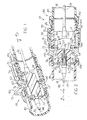
- Fig. 1 is a partially sectional view of an optic fiber connector system of the present invention, with a pair of plex connectors mounted in the plex housing.
- Fig. 2 is a partial sectional side elevation view of the connector system of Fig. 1 .
- Fig. 3 is a front isometric view of the middle shell of the shell assembly of Fig. 2 .
- Fig. 4 is a partial side elevation view similar to that of Fig. 2 , showing a grommet at the end of one of the backshells.
- Fig. 1 illustrates an optic fiber connector system 10 of the present invention which includes a plex connector housing 12 thathas at least one through bore 14 with opposite ends that each receives a plexconnector 20, 22.
- the plex connectors are similar in shape to common telephone-type connectors that plug into household telephone wall sockets. The bore opposite ends are spaced in front F and rear R longitudinal directions.
- each plex connector such as 22 includes a plex frame 23 that has a plex passage 24 that receives a plex terminus 26. The walls of the plex passage 24 are thin.
- Each plex connector is connected to an optical fiber cable 32, 34 which includes an optical fiber 36, 38.
- Each optical fiber extends completely through a corresponding terminus, and the tips 40, 42 of two fibers abut one another within an alignment sleeve portion 44 of the through bore 14.
- Each plexconnector 20, 22 is locked in the through bore by a latch 50 that can be unlatched. ln Fig. 2 , unlatching is accomplished by depressing a handle 52.
- the plex housing 12 is generally of rectangulacross-section, and can be fixed in a panel by an outer flange 60 and a flexible stop 62.
- Applicant uses the term "plex" to describe simple optic fiber systems, wherein each fiber generally lies in a separate connector frame that can be easily pushed into and pulled out of a plex housing bore.
- Such plex systems generally require a much greater volume for connecting many optic cables together, than military systems where a single housing has many bores that each receives a fiber-holding terminus, with a special tool required to remove a terminus.
- plex connectors are versatile in that they can be easily plugged into and removed from a plex housing, and spares are readily available.
- the plex system itself which includes the plex housing 12and the pair of plex connectors 20, 22 are satisfactory for many applications where a panel on which the plex housing 12 is mountedies in a clean environment. However, in a harsh environment, where the plex housing 12 may be struck or where there is a lot of dust or vapor in the air which might find its way into the plex housing bore 14, the plexsystem is not satisfactory.
- Another available system is the military optical fiber connector system, which is expensive.
- a moderately priced optical fiber connection system 10 which is based ona plex system that includes a low cost plex connector housing 12 and low costand easily removed (without special tools) plex connectors 20, 22 that each forms its own frame with a terminus-receiving passage.
- Applicant adds an assembly 70 of shells that surround the plex housing12, and that also surround the plex connectors 20, 22 that connect to each other in the connector housing and optic fiber cables 32, 34 that extend from the plex connectors.
- the shell assembly 70 includes a middle shell 72 that has externally threaded front and rear middle shell portions 74, 76.
- the shell assembly also includes front and rear backshells 80, 82 that respectively project forwardly and rearwardly from the middle shell 72.
- the shells are primarily of cylindrical shape with a shell axis 88.
- the front backshell 80 includes a front backs hell member 84, a plug barrel part 86 that serves as a rearward extension of the front backshell member 84, and a coupling nut 90.
- the backshell member 84 and rear backshell 82 can be identical.
- the coupling nut 90 threadably engages the front threaded end 74 of the middle shell and an outer flange 92 on the plug barrel part. When the coupling nut 90 is tightened, it pushes a shoulder 93 on the flange 92 rearward and causes the plug barrel 86 to compress a seal1 00. Additional seals 102, 104 seathe shell members to one another.
- Fig. 4 shows that grommets 110 sealeach optic fiber cable suchas 32 to the corresponding backshell or backshell member such as 84.
- the middle shell 72 ( Fig. 2 ) has an internal flange 120 with a cylindrical radially outer part that merges with the rest of the middle shell, and with a rectangular passage 122 thatclosely receives the plex housing12.
- the plex housing has flanges 60 that abut rearwardly-facing shoulders 126of the middle shell flange.
- the plex housing also includes pop up latches 62 that abut an opposite forwardly-facing shoulder 130 of the middleshell internal flange.
- the particulaplex housing 12 has two bores14, 15 for connecting two pairs of mating plex connectors.
- a plex housing with one or with more than two bores is available, but this usually requires a larger shell assembly. It is noted that a military connector could hold perhaps ten or more optical termini in the same space because it has a single housing with multiple bores.
- the shell assembly 70 ( Fig. 2 ) can be mounted on an existing or new plex system which includes the plex housing 12 and one or morepairs of plex connectors 20, 22 and corresponding optic fiber cables 32, 34 extending therefrom.
- the middle shell 72 With the middle shell 72 not connected to other parts, the plex housing 12 is pushed forwardly F into the middle shell internaflange passage 122 until the latches 62 snap into place.
- Thefront backs hell assembly or front backs hell 80 is inserted into a front passageway portion 142 of the middle shell and the coupling nut 90 is held inplace by a snap ring 144.
- the front backshell member 84 will have been alreadyscrewed onto the rear of the plug barrel part 86.
- the rear backshell 82 is screwed onto the rear end of the middleshell.
- Grommets such as 110 will have been already threaded onto the cables 32, 34 and will be pressed into the insides of the backshells, as shown in Fig. 4 .
- the shell assembly 70 does not affect the optical coupling of the fibers or the plex connectors, and only seals to the cables extending from the plex connectors. However, the shell assembly provides a sealed environment for the plex connectors and provides protection against physical damage to the plex connector assembly.
- the middle shell has an outer flange 150 with holes that can be mounted on a panel.
- the middle shell 72 is preferably formed of metal (e.g. stainless steel).
- the backshells 80, 82 can be formed of high strength polymer. The greater thickness of the walls of the backshells 80, 82, than the walls 152of the plex connector, results in increased strength.
- the invention provides an optical fiber connector system which uses a simple and versatile plex system for optical connections but which uses a shell assembly to protect the plex system from dust, vapors, etc. that might seep in and to protect the plex system from physical damage by being struck, crushed, etc.
- the shell assembly includes a middle shell with an internal flange that closely receives the plex housing and which is similar to a panel to which the plex housing can directly latch.
- Backshells extending in front and rearward direction from the middle shell, extend to optical cable portions remote from the plex connectors and provide elastomeric grommets that seal to the cables.
Landscapes
- Physics & Mathematics (AREA)
- General Physics & Mathematics (AREA)
- Optics & Photonics (AREA)
- Mechanical Coupling Of Light Guides (AREA)
Claims (7)
- Lichtwellenleiter-Steckverbindersystem, enthaltend ein Gehäuse (12), welches mindestens eine Durchgangsbohrung (14) mit in Längsrichtung beabstandeten, einander gegenüberliegenden vorderen und hinteren Enden hat, welche Bohrungsenden jeweils zueinander passende Lichtwellenleiter-Steckverbinder (20, 22) aufnehmen und verriegeln, wobei jeder Steckverbinder einen äußeres Gehäuse (23) mit einem Durchgangskanal (24), ein Lichtwellenleiter-Endelement (26), welches in dem Durchgangskanal liegt, aufweist, wobei ein Lichtwellenleiterkabel (32, 34) mit dem Lichtwellenleiter durch den Durchgangskanal verläuft, wobei das Gehäuse des Steckverbindersystems enthält:eine Anordnung (70) einer Vielzahl von rohrförmigen Schalen, die auf einer Achse (88) liegt, welche Schalen eine Mittelschale (72), welche die äußeren Gehäuse eng aufnimmt, sowie eine vordere und eine hintere Endschale (80, 82) enthält, die jeweils in Bezug auf die Mittelschale abgedichtet sind und die sich von der Mittelschale nach vorne bzw. nach hinten erstrecken; jeweilige Elastomer-Kabeltüllen (110), die jeweils in einer der Endschalen liegen, wobei jede Kabeltülle einen Umfang hat, welcher mit ihrer entsprechenden Endschale versiegelt ist, und jede Kabeltülle einen inneren mittleren Abschnitt hat, der mit jeweils einem der Lichtwellenleiterkabel versiegelt ist.
- Steckverbindersystem nach Anspruch 1, bei welchem:die Anordnung von Schalen eine vordere und eine hintere Endschale (80, 82) mit zylindrischen Gewindeenden und eine Mittelschale (72) mit einem zylindrischen vorderen und hinteren Gewindeende (74, 76) umfasst, die mit den Enden der Endschalen verschraubt sind, wobei die Mittelschale einen Innenflansch (120) hat, welcher Flansch eine vordere und eine hintere Oberfläche (126, 130) hat, und das Gehäuse ein Paar Absätze bildet, welche an der vorderen und der hinteren Flanschoberfläche anliegen.
- Steckverbindersystem nach Anspruch 2, bei welchem:das Gehäuse (12) entlang der Vorwärts- und Rückwärtsrichtung betrachtet einen rechteckigen Querschnitt aufweist, wobei der Mittelflansch (120) einen zylindrischen mittleren Abschnitt hat und der interne Flansch ein zylindrisches radial äußeres Ende und einen rechteckigen Durchgangskanal (122) hat, welcher das Gehäuse eng aufnimmt.
- Steckverbindersystem nach Anspruch 2, enthaltend:eine Vielzahl von Dichtungen (100, 104), welche das vordere und das hintere Ende der Mittelschale mit der vorderen und der hinteren Endschale abdichten.
- Steckverbindersystem nach Anspruch 1, bei welchem:die Mittelschale ein vorderes und ein hinteres Ende (74, 76) mit Außengewinde hat und die Endschalen Enden mit Innengewinde haben, wobei die hintere Endschale ein vorderes Ende mit Gewinde hat, das mit dem hinteren Gewindeende (46) der Mittelschale verschraubt ist;die vordere Endschale einen Steckzylinderteil (86) mit einem vorderen Abschnitt aufweist, welcher in das vordere Ende der Mittelschale passt, welcher Steckzylinderteil einen nach vorne weisenden Absatz (93) hat, und die vordere Endschale eine Überwurfmutter (90) hat, welche ein hinteres Ende mit Innengewinde hat, welches mit dem vorderen Ende (74) der Mittelschale in Gewindeeingriff steht, wobei die Überwurfmutter ein vorderes Ende mit einem nach hinten weisenden Absatz hat, welcher an dem nach vorne weisenden Absatz des Steckzylinderteils anliegt, wodurch die Demontage ermöglicht wird, ohne dass die vordere Endschale und das vorderste Lichtwellenleiterkabel gedreht werden müssen.
- Verfahren zur Verwendung eines Plex-Lichtwellenleiter-Steckverbindersystems, welches ein Plex-Gehäuse (12) mit einer entsprechenden Anzahl von Durchgangsbohrungen (14) sowie ein Paar von zueinander passenden Plex-Steckverbinderanordnungen enthält, die jeweils einen Plex-Steckverbinder (20, 22) und ein Lichtwellenleiterkabel (32, 34) enthalten, die eine entsprechende Anzahl von in dem Steckverbinder liegenden Lichtwellenleitern haben und Faserenden an einem Ende des Steckverbinders haben, wobei die Plex-Steckverbinder in gegenüberliegende Enden der entsprechenden Bohrungen einführbar sind, so dass die Lichtwellenleiter-Faserenden aneinander anliegen, während die Faserenden gegen physische Beschädigung und gegen Dämpfe in einer rauen Umgebung geschützt sind, enthaltend:Montieren des Plex-Gehäuses in einer Anordnung (70) einer Vielzahl von starren rohrförmigen Schalen;Abdichten der Schalen der Anordnung von Schalen gegeneinander und Verwenden von jeweiligen Elastomer-Kabeltüllen zum Versiegeln der jeweiligen Lichtwellenleiterkabel an entgegengesetzten Enden der Anordnung von Schalen, wobei jede Kabeltülle einen Umfang hat, der mit einer jeweiligen Schale versiegelt ist, und einen inneren mittleren Abschnitt, der jeweils mit einem Kabel versiegelt ist, um dadurch die Plex-Steckverbinder und die Faserenden der Lichtwellenleiter zu schützen.
- Verfahren nach Anspruch 6, bei welchem:der Schritt des Montierens des Plex-Gehäuses das Einschieben des Plex-Gehäuses in eine Öffnung (122) in einem internen Flansch (120) einer Mittelschale (72), welche ein vorderes und ein hinteres, mit Gewinde versehenes Ende (74, 76) hat, und Verschrauben einer vorderen und einer hinteren Endschale (80, 82) mit den entgegengesetzten Enden der Mittelschale umfasst;der Schritt des Abdichtens das Aufschieben einer Elastomer-Kabeltülle (110) entlang dem Lichtwellenleiterkabel einer ersten der Plex-Steckverbinderanordnungen und in ein Ende einer der Endschalen umfasst.
Applications Claiming Priority (2)
| Application Number | Priority Date | Filing Date | Title |
|---|---|---|---|
| US10/388,708 US6739759B1 (en) | 2003-03-13 | 2003-03-13 | Protected optical interface |
| US388708 | 2003-03-13 |
Publications (3)
| Publication Number | Publication Date |
|---|---|
| EP1457793A2 EP1457793A2 (de) | 2004-09-15 |
| EP1457793A3 EP1457793A3 (de) | 2005-02-02 |
| EP1457793B1 true EP1457793B1 (de) | 2009-09-23 |
Family
ID=32312421
Family Applications (1)
| Application Number | Title | Priority Date | Filing Date |
|---|---|---|---|
| EP04100748A Expired - Lifetime EP1457793B1 (de) | 2003-03-13 | 2004-02-26 | Geschützte Optische Schnittstelle |
Country Status (2)
| Country | Link |
|---|---|
| US (1) | US6739759B1 (de) |
| EP (1) | EP1457793B1 (de) |
Families Citing this family (29)
| Publication number | Priority date | Publication date | Assignee | Title |
|---|---|---|---|---|
| US6962445B2 (en) * | 2003-09-08 | 2005-11-08 | Adc Telecommunications, Inc. | Ruggedized fiber optic connection |
| US7213975B2 (en) | 2004-09-10 | 2007-05-08 | Adc Telecommunications, Inc. | Hybrid fiber/copper connector system and method |
| US7393144B2 (en) * | 2005-04-15 | 2008-07-01 | Adc Telecommunications, Inc. | Hybrid fiber/copper connector system and method |
| US7481585B2 (en) * | 2006-11-29 | 2009-01-27 | Adc Telecommunications, Inc. | Hybrid fiber/copper connector system and method |
| US7490994B2 (en) * | 2006-11-29 | 2009-02-17 | Adc Telecommunications, Inc. | Hybrid fiber/copper connector system and method |
| US7591595B2 (en) | 2007-01-24 | 2009-09-22 | Adc Telelcommunications, Inc. | Hardened fiber optic adapter |
| US7614797B2 (en) * | 2007-01-24 | 2009-11-10 | Adc Telecommunications, Inc. | Fiber optic connector mechanical interface converter |
| US7572065B2 (en) | 2007-01-24 | 2009-08-11 | Adc Telecommunications, Inc. | Hardened fiber optic connector |
| US7556437B2 (en) * | 2007-03-13 | 2009-07-07 | Adc Telecommunications, Inc. | Fiber optic connector with protective cap |
| WO2008137897A1 (en) * | 2007-05-06 | 2008-11-13 | Adc Telecommunications, Inc. | Mechanical interface converter for making non-ruggedized fiber optic connectors compatible with a ruggedized fiber optic adapter |
| US7722258B2 (en) * | 2007-05-06 | 2010-05-25 | Adc Telecommunications, Inc. | Interface converter for SC fiber optic connectors |
| US7686519B2 (en) * | 2007-06-18 | 2010-03-30 | Adc Telecommunications, Inc. | Hardened fiber optic housing and cable assembly |
| US8083416B2 (en) | 2007-11-30 | 2011-12-27 | Adc Telecommunications, Inc. | Hybrid fiber/copper connector system and method |
| US7744286B2 (en) | 2007-12-11 | 2010-06-29 | Adc Telecommunications, Inc. | Hardened fiber optic connection system with multiple configurations |
| US9392941B2 (en) | 2010-07-14 | 2016-07-19 | Adidas Ag | Fitness monitoring methods, systems, and program products, and applications thereof |
| US9549598B2 (en) | 2010-10-12 | 2017-01-24 | Treefrog Developments, Inc. | Housing for encasing an electronic device |
| JP5916996B2 (ja) * | 2010-12-28 | 2016-05-11 | Seiオプティフロンティア株式会社 | 光コネクタ及び光コネクタの組立方法 |
| DE102011011523B4 (de) * | 2011-02-17 | 2013-05-29 | Tyco Electronics Services Gmbh | Faseroptische Verbindungsanordnung und Adapterhülse |
| ES2700963T3 (es) | 2013-06-27 | 2019-02-20 | CommScope Connectivity Belgium BVBA | Dispositivo de anclaje para cable de fibra óptica para uso con conectores de fibra óptica y métodos de uso del mismo |
| US9300078B2 (en) * | 2013-08-23 | 2016-03-29 | Otter Products, Llc | Waterproof housing for mobile electronic device and waterproof adapter for accessory device |
| US9577697B2 (en) | 2015-05-27 | 2017-02-21 | Otter Products, Llc | Protective case with stylus access feature |
| US9960521B2 (en) | 2016-02-24 | 2018-05-01 | Otter Products, Llc | Connector for fluidly sealing an aperture of a protective case |
| US10591677B2 (en) * | 2016-03-09 | 2020-03-17 | Preformed Line Products, Co. | Retrofit cover for fiber optic cable connection |
| US9869823B1 (en) * | 2016-07-28 | 2018-01-16 | CommScope Technologies | Self-sealing hybrid power/fiber connector |
| EP3519872B1 (de) | 2016-09-27 | 2021-06-09 | Prysmian S.p.A. | Verbinder für vorkonnektorisierte glasfaserkabel |
| US10873161B2 (en) * | 2019-05-06 | 2020-12-22 | Te Connectivity Corporation | Receptacle assembly having cabled receptacle connector |
| WO2021188099A1 (en) * | 2020-03-17 | 2021-09-23 | Preformed Line Products Co. | Retrofit cover for fiber optic cable connection |
| US11211743B2 (en) * | 2020-03-18 | 2021-12-28 | TE Connectivity Services Gmbh | Receptacle module and receptacle cage for a communication system |
| US11489293B2 (en) * | 2020-12-21 | 2022-11-01 | Te Connectivity Solutions Gmbh | Receptacle module and receptacle cage for a communication system |
Family Cites Families (19)
| Publication number | Priority date | Publication date | Assignee | Title |
|---|---|---|---|---|
| US4140367A (en) | 1976-10-08 | 1979-02-20 | Bunker Ramo Corporation | Multiple channel connector for fiber optic cables |
| US4140366A (en) | 1977-04-19 | 1979-02-20 | Bunker Ramo Corporation | Fiber optic connector assembly |
| US4193655A (en) * | 1978-07-20 | 1980-03-18 | Amp Incorporated | Field repairable connector assembly |
| EP0056192A1 (de) * | 1981-01-08 | 1982-07-21 | Litton Systems, Inc. | Faseroptische Verbindung, Verfahren zur Herstellung der Verbindung und faseroptisches Kabel zur Verwendung in der Verbindung |
| JPS6270805A (ja) | 1985-09-25 | 1987-04-01 | Furukawa Electric Co Ltd:The | 光・メタル複合ケ−ブル端末部 |
| DE4230138A1 (de) * | 1992-09-09 | 1994-03-10 | Wilo Gmbh | Kabelbefestigungsvorrichtung für eine Pumpe |
| US5408557A (en) | 1994-04-20 | 1995-04-18 | Hsu; Chung-Tang | FC-type optical fiber cable connector's adaptor |
| US5796896A (en) * | 1996-03-14 | 1998-08-18 | Minnesota Mining And Manufacturing Company | Multi-ferrule fiber optic connector for high density backplane applications |
| US5689598A (en) | 1996-06-11 | 1997-11-18 | Siecor Corporation | Connector block and method for simultaneously mating a plurality of optical fiber connector pairs |
| US5920669A (en) | 1997-06-06 | 1999-07-06 | Siecor Corporation | Receptacle having a rotatable coupling nut for engaging a fiber optic connector assembly |
| US5870515A (en) | 1997-06-06 | 1999-02-09 | Siecor Corporation | Receptacle and associated method for permitting the selective withdrawal of a ferrule |
| US5923802A (en) | 1997-06-06 | 1999-07-13 | Siecor Corporation | Flexible connector assembly having slack storage |
| US5923805A (en) * | 1997-12-22 | 1999-07-13 | Lucent Technologies Inc. | Connector for plastic optical fiber |
| US6264374B1 (en) | 1998-09-09 | 2001-07-24 | Amphenol Corporation | Arrangement for integrating a rectangular fiber optic connector into a cylindrical connector |
| US6206579B1 (en) | 1998-10-29 | 2001-03-27 | Amphenol Corporation | Arrangement for integrating a rectangular fiber optic connector into a cylindrical connector |
| US6203210B1 (en) * | 1999-04-16 | 2001-03-20 | Wiremold Interlink Cabling System | Fiber optic connector |
| US6238101B1 (en) * | 1999-07-08 | 2001-05-29 | Molex Incorporated | Tunable fiber optic connector |
| US6234683B1 (en) | 1999-09-13 | 2001-05-22 | Stratos Lightwave, Inc. | Field repairable hermaphroditic connector |
| US6623289B2 (en) * | 2001-06-14 | 2003-09-23 | Manny Silverio | Explosion-proof instrument quick disconnect and seal |
-
2003
- 2003-03-13 US US10/388,708 patent/US6739759B1/en not_active Expired - Fee Related
-
2004
- 2004-02-26 EP EP04100748A patent/EP1457793B1/de not_active Expired - Lifetime
Also Published As
| Publication number | Publication date |
|---|---|
| EP1457793A2 (de) | 2004-09-15 |
| EP1457793A3 (de) | 2005-02-02 |
| US6739759B1 (en) | 2004-05-25 |
Similar Documents
| Publication | Publication Date | Title |
|---|---|---|
| US6739759B1 (en) | Protected optical interface | |
| US11971585B2 (en) | Ruggedized fiber optic connectors and connection systems | |
| US11726270B2 (en) | Optical fiber connector and method of assembling the same on site | |
| US20250321386A1 (en) | Sealing enclosure for a connector on a cable such as a standardized fiber-optic connector | |
| US10948660B2 (en) | Connecting piece and optical fiber connector | |
| US7686519B2 (en) | Hardened fiber optic housing and cable assembly | |
| US7338214B1 (en) | Method and apparatus for sealing fiber optic connectors for industrial applications | |
| US10871617B2 (en) | Hardened converter and sealing shell for field terminated connector | |
| EP3167321B1 (de) | Optische ferrule für multifaserkabel und gehärteter multiglasfaserstecker dafür | |
| US20080175542A1 (en) | Hardened fiber optic adapter | |
| US20070036487A1 (en) | Industrial optical fiber connector assembly | |
| US20100172616A1 (en) | Mechanical interface converter for making non-ruggedized fiber optic connectors compatible with a ruggedized fiber optic adapter | |
| US8485736B2 (en) | Optical connector | |
| US20250347855A1 (en) | Ruggedized push-pull fiber optic connection systems | |
| WO2021026482A1 (en) | Push pull mechanism for an outdoor rated connector assembly | |
| US11886030B2 (en) | Optical fiber connector with improved cable retention strength | |
| EP4402524A1 (de) | Wandler für faseroptische verbinder |
Legal Events
| Date | Code | Title | Description |
|---|---|---|---|
| PUAI | Public reference made under article 153(3) epc to a published international application that has entered the european phase |
Free format text: ORIGINAL CODE: 0009012 |
|
| AK | Designated contracting states |
Kind code of ref document: A2 Designated state(s): AT BE BG CH CY CZ DE DK EE ES FI FR GB GR HU IE IT LI LU MC NL PT RO SE SI SK TR |
|
| AX | Request for extension of the european patent |
Extension state: AL LT LV MK |
|
| PUAL | Search report despatched |
Free format text: ORIGINAL CODE: 0009013 |
|
| AK | Designated contracting states |
Kind code of ref document: A3 Designated state(s): AT BE BG CH CY CZ DE DK EE ES FI FR GB GR HU IE IT LI LU MC NL PT RO SE SI SK TR |
|
| AX | Request for extension of the european patent |
Extension state: AL LT LV MK |
|
| RIC1 | Information provided on ipc code assigned before grant |
Ipc: 7G 02B 6/38 A |
|
| 17P | Request for examination filed |
Effective date: 20050802 |
|
| AKX | Designation fees paid |
Designated state(s): FI FR GB |
|
| REG | Reference to a national code |
Ref country code: DE Ref legal event code: 8566 |
|
| RIC1 | Information provided on ipc code assigned before grant |
Ipc: G02B 6/38 20060101ALI20070216BHEP Ipc: G02B 6/00 20060101AFI20070216BHEP |
|
| GRAP | Despatch of communication of intention to grant a patent |
Free format text: ORIGINAL CODE: EPIDOSNIGR1 |
|
| GRAS | Grant fee paid |
Free format text: ORIGINAL CODE: EPIDOSNIGR3 |
|
| GRAA | (expected) grant |
Free format text: ORIGINAL CODE: 0009210 |
|
| AK | Designated contracting states |
Kind code of ref document: B1 Designated state(s): FI FR GB |
|
| REG | Reference to a national code |
Ref country code: GB Ref legal event code: FG4D |
|
| PLBE | No opposition filed within time limit |
Free format text: ORIGINAL CODE: 0009261 |
|
| STAA | Information on the status of an ep patent application or granted ep patent |
Free format text: STATUS: NO OPPOSITION FILED WITHIN TIME LIMIT |
|
| 26N | No opposition filed |
Effective date: 20100624 |
|
| GBPC | Gb: european patent ceased through non-payment of renewal fee |
Effective date: 20100226 |
|
| REG | Reference to a national code |
Ref country code: FR Ref legal event code: ST Effective date: 20101029 |
|
| PG25 | Lapsed in a contracting state [announced via postgrant information from national office to epo] |
Ref country code: FI Free format text: LAPSE BECAUSE OF NON-PAYMENT OF DUE FEES Effective date: 20100226 |
|
| PG25 | Lapsed in a contracting state [announced via postgrant information from national office to epo] |
Ref country code: FR Free format text: LAPSE BECAUSE OF NON-PAYMENT OF DUE FEES Effective date: 20100301 |
|
| PG25 | Lapsed in a contracting state [announced via postgrant information from national office to epo] |
Ref country code: GB Free format text: LAPSE BECAUSE OF NON-PAYMENT OF DUE FEES Effective date: 20100226 |