EP1457799B1 - Lagerfusspaar und Lagervorrichtung, insbesondere für einen Laserresonator - Google Patents
Lagerfusspaar und Lagervorrichtung, insbesondere für einen Laserresonator Download PDFInfo
- Publication number
- EP1457799B1 EP1457799B1 EP03005188A EP03005188A EP1457799B1 EP 1457799 B1 EP1457799 B1 EP 1457799B1 EP 03005188 A EP03005188 A EP 03005188A EP 03005188 A EP03005188 A EP 03005188A EP 1457799 B1 EP1457799 B1 EP 1457799B1
- Authority
- EP
- European Patent Office
- Prior art keywords
- bearing
- supporting device
- coupled
- support feet
- feet
- Prior art date
- Legal status (The legal status is an assumption and is not a legal conclusion. Google has not performed a legal analysis and makes no representation as to the accuracy of the status listed.)
- Expired - Lifetime
Links
- 239000007788 liquid Substances 0.000 claims abstract description 8
- 239000012530 fluid Substances 0.000 claims description 3
- 238000001816 cooling Methods 0.000 description 4
- 238000004904 shortening Methods 0.000 description 3
- 230000008878 coupling Effects 0.000 description 2
- 238000010168 coupling process Methods 0.000 description 2
- 238000005859 coupling reaction Methods 0.000 description 2
- 239000000463 material Substances 0.000 description 2
- 230000007613 environmental effect Effects 0.000 description 1
- 238000010438 heat treatment Methods 0.000 description 1
- 238000003466 welding Methods 0.000 description 1
Images


Classifications
-
- G—PHYSICS
- G01—MEASURING; TESTING
- G01M—TESTING STATIC OR DYNAMIC BALANCE OF MACHINES OR STRUCTURES; TESTING OF STRUCTURES OR APPARATUS, NOT OTHERWISE PROVIDED FOR
- G01M11/00—Testing of optical apparatus; Testing structures by optical methods not otherwise provided for
- G01M11/02—Testing optical properties
- G01M11/04—Optical benches therefor
-
- G—PHYSICS
- G02—OPTICS
- G02B—OPTICAL ELEMENTS, SYSTEMS OR APPARATUS
- G02B7/00—Mountings, adjusting means, or light-tight connections, for optical elements
- G02B7/003—Alignment of optical elements
-
- H—ELECTRICITY
- H01—ELECTRIC ELEMENTS
- H01S—DEVICES USING THE PROCESS OF LIGHT AMPLIFICATION BY STIMULATED EMISSION OF RADIATION [LASER] TO AMPLIFY OR GENERATE LIGHT; DEVICES USING STIMULATED EMISSION OF ELECTROMAGNETIC RADIATION IN WAVE RANGES OTHER THAN OPTICAL
- H01S3/00—Lasers, i.e. devices using stimulated emission of electromagnetic radiation in the infrared, visible or ultraviolet wave range
- H01S3/02—Constructional details
Definitions
- the present invention relates to a bearing pair of two bearing feet and a bearing device, in particular for a laser resonator.
- Such a bearing foot and such a bearing device have become known for example from EP 1 267 458 A1.
- the known storage device serves as a substructure for a square-structured laser resonator, which consists of a resonator frame and a decoupling block and three Umlenkblöcken, which are bolted to the Resonatorrahmen.
- the decoupling block includes a Auskoppel- and a rearview mirror, and at a
- a double-square laser resonator with two discharge planes additionally has a retroreflector, which deflects the laser beam from the first discharge plane into the second discharge plane.
- the deflection blocks each contain a deflection mirror, which deflects the laser beam by 90 °.
- the bearing device comprises three bearing feet arranged on a base plate, which form a 3-point bearing.
- the arranged below the decoupling block first bearing is designed as a fixed bearing, which has two rotational and no translational degree of freedom, and arranged below a Umlenkblocks second bearing foot is designed as a one-dimensional movable bearing having two rotational and one translational degree of freedom.
- the third bearing foot is arranged between two deflection blocks and designed as a two-dimensional floating bearing that allows movements with two rotational and two translatory degrees of freedom.
- the decoupling block and a Umlenkblock are relatively well supported, while the other two Umlenkblöcke hang "floating" on the resonator, which is thereby unbalanced load.
- the object of the present invention is therefore to provide a Lagerfußcru and a bearing device that can accommodate the introduced forces as symmetrical as possible.
- a shortening of the one bearing foot leads to a corresponding elongation of the other bearing foot, whereby the force is distributed under load in a ratio of 1: 1 on both bearing feet.
- the height adjustment is achieved by one or two height-spaced bellows, which can be axially lengthen or shortened by little effort and withstand high pressures.
- two axially spaced bellows per bearing foot this acts like a universal joint, whereby a two-dimensional floating bearing is formed.
- the two bearing feet are telescopically extendable and each with a fluid, in particular with a fluid such. Oil filled, which is incompressible at least in the forces occurring during operation.
- the bearing feet have a displaceable by means of the incompressible liquid piston, which is sealed with a 0-ring in a cylinder guide. Material and geometry, i. Ratio of length to diameter, the bearing foot are selected so that a change in volume of the liquid medium due to temperature change is compensated by an expansion of the bearing foot in the radial direction and not by a length expansion of the bellows.
- the opposite height coupling of the two bearing feet is most easily hydraulically by the two filled with the incompressible liquid bearing feet are connected to each other via a pipe.
- the opposite height coupling of the two bearing feet can also be done electrically or mechanically.
- the two bearing feet can be designed as a fixed bearing or as a one or two-dimensional floating bearing.
- a bearing device in particular as a substructure for a laser resonator, with four bearing feet, two of which are formed as described above.
- the resonator frame is mounted on at least four bearing feet and thus symmetrical. Since two of the four bearing feet are height coupled together, this statically determined 4-point resonator bearing is not overdetermined. There one Shortening of a bearing foot leads to a corresponding elongation of the coupled other bearing foot, the force is distributed under load in a ratio of 1: 1 on both bearing feet, and the resonator frame is loaded almost symmetrical. Even thermal gear of the base plate does not lead to a distortion of the Resonatorrahmens by this storage.
- the two mutually coupled bearing feet are each formed as a two-dimensional movable bearing and the other two bearing feet as a fixed bearing and a one-dimensional floating bearing.
- Fig. 1 shows a pair of bearing feet 1 , the two bearing feet 2 are each height adjustable and height-coupled in opposite directions.
- the two identically constructed bearing feet 2 each have a bottom flange 3 , a head flange 4 and in between a tube 5 , which is connected to the bottom and top flange 3, 4 each have a bellows 6, 7 .
- the defined by the pipe 5 and the bellows 6, 7 inner spaces 8 of the bearing feet 2 are filled with a liquid (eg oil), which is incompressible at least in the forces occurring during operation.
- the two Interior spaces 8 of the bearing feet 2 are connected to one another via a connecting line 9 (FIG. 3), which is in each case connected to a connecting piece 10 on the bottom flange 3.
- both bearing feet 2 are each axially displaceable and thus adjustable in height.
- both bearing feet 2 are coupled in opposite directions hydraulically, ie a shortening of the one bearing foot 2 um - dz leads to a corresponding elongation + dz of the other bearing foot 2, whereby the force under load in the ratio 1: 1 on both bearing feet distributed.
- the difference due to friction losses and the different forces of the bellows (+ dz and -dz) is negligible.
- this acts like a universal joint, so that the two bearing feet 2 each act as a 2-dimensional floating bearing.
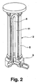
- Fig. 2 shows the bearing 2 with integrated cooling of the liquid medium, which prevents heating of the bearing foot 2 by the environmental conditions during operation.
- the cooling comprises a in the interior 8 U-shaped extending cooling line 11, the connections are provided in the bottom flange 3.
- Material and geometry, ie ratio of length to diameter, of the bearing foot are selected so that a change in volume of the liquid medium due to temperature change is compensated by an expansion of the bearing foot in the radial direction and not by a length expansion of the bellows.
- Fig. 3 shows a bearing device 20 with four mounted on a base plate 21 bearing feet, of which two bearing feet 2 as described in Fig. 1 are formed.
- the bearing device 20 serves as a substructure for a laser resonator 22, which consists of a resonator frame 23 and four decoupling and deflection blocks 24, 25 screwed thereto.
- the two coupled bearing feet 2 are each designed as a two-dimensional floating bearing and the two other bearing feet 26, 27 as a fixed bearing and a one-dimensional floating bearing.
Landscapes
- Physics & Mathematics (AREA)
- General Physics & Mathematics (AREA)
- Optics & Photonics (AREA)
- Electromagnetism (AREA)
- Lasers (AREA)
- Chemical & Material Sciences (AREA)
- Analytical Chemistry (AREA)
- Engineering & Computer Science (AREA)
- Plasma & Fusion (AREA)
- Support Of The Bearing (AREA)
Description
- Die vorliegende Erfindung betrifft ein Lagerfußpaar aus zwei Lagerfüßen sowie eine Lagervorrichtung, insbesondere für einen Laserresonator.
- Ein derartiger Lagerfuß und eine derartige Lagervorrichtung sind beispielsweise durch die EP 1 267 458 A1 bekannt geworden.
- Die bekannte Lagervorrichtung dient als Unterbau für einen quadratisch aufgebauten Laserresonator, der aus einem Resonatorrahmen sowie einem Auskoppelblock und drei Umlenkblöcken besteht, die mit dem Resonatorrahmen verschraubt sind. Der Auskoppelblock enthält einen Auskoppel- und einen Rückspiegel, und bei einem doppelt quadratisch aufgebauten Laserresonator mit zwei Entladungsebenen zusätzlich einen Retroreflektor, der den Laserstrahl aus der ersten Entladungsebene in die zweite Entladungsebene umlenkt. Die Umlenkblöcke enthalten jeweils einen Umlenkspiegel, der den Laserstrahl um 90° umlenkt. Die Lagervorrichtung umfasst drei auf einer Grundplatte angeordnete Lagerfüße, die eine 3-Punkt-Lagerung bilden. Der unterhalb des Auskoppelblocks angeordnete erste Lagerfuß ist als Festlager ausgebildet, das zwei rotatorische und keinen translatorischen Freiheitsgrad besitzt, und der unterhalb eines Umlenkblocks angeordnete zweite Lagerfuß ist als eindimensionales Loslager ausgebildet, das zwei rotatorische und einen translatorischen Freiheitsgrad besitzt. Der dritte Lagerfuß ist zwischen zwei Umlenkblöcken angeordnet und als zweidimensionales Loslager ausgebildet, das Bewegungen mit zwei rotatorischen und zwei translatorischen Freiheitsgraden zulässt. Diese Anordnung stellt sicher, dass bei thermischer Ausdehnung des Resonatorrahmens die Strahlachse nahezu unverändert bleibt und thermische Ausdehnungen der Grundplatte nicht auf den Resonatorrahmen übertragen werden. Bei dieser Anordnung erfolgt die Krafteinleitung in den Resonatorrahmen allerdings unsymmetrisch. Der Auskoppelblock und ein Umlenkblock sind relativ gut abgestützt, während die beiden weiteren Umlenkblöcke jedoch "frei schwebend" am Resonatorrahmen hängen, der dadurch unsymmetrisch belastet wird. Zu der Belastung durch die Gewichtskraft der Blöcke, die tendenziell mit steigenden Laserleistungen in den letzten Jahren zunahm, kommt noch die Belastung durch die Vakuumkraft, die über die Blöcke auf den Resonatorrahmen wirkt.
- Die Aufgabe der vorliegenden Erfindung ist es daher, ein Lagerfußpaar und eine Lagervorrichtung bereitzustellen, die die eingeleiteten Kräfte möglichst symmetrisch aufnehmen können.
- Diese Aufgabe wird bei einem Lagerfußpaar erfindungsgemäß dadurch gelöst, dass die beiden Lagerfüße jeweils höhenverstellbar und miteinander gegenläufig höhengekoppelt sind.
- Eine Verkürzung des einen Lagerfußes führt zu einer entsprechenden Längung des anderen Lagerfußes, wodurch sich die Kraft bei Belastung im Verhältnis 1:1 auf beide Lagerfüße verteilt.
- Vorzugsweise wird die Höhenverstellbarkeit durch einen oder zwei voneinander höhenbeabstandete Faltenbälge gelöst, die sich durch wenig Kraftaufwand axial längen bzw. verkürzen lassen und hohen Drücken standhalten. Durch den Einsatz zweier axial beabstandeter Faltenbälge pro Lagerfuß wirkt dieser wie ein Kardangelenk, wodurch ein zweidimensionales Loslager gebildet wird.
- Bei einer bevorzugten Ausführungsform der Erfindung sind die beiden Lagerfüße teleskopartig ausziehbar und jeweils mit einem Fluid, insbesondere mit einer Flüssigkeit wie z.B. Öl, gefüllt, die zumindest bei den im Betrieb auftretenden Kräften inkompressibel ist. Bei einer anderen Ausführungsform weisen die Lagerfüße einen mittels der inkompressiblen Flüssigkeit verschiebbaren Kolben auf, der mit einem 0-Ring in einer Zylinderführung abgedichtet ist. Material und Geometrie, d.h. Verhältnis von Länge zu Durchmesser, des Lagerfußes werden so ausgewählt, dass eine Volumenänderung des Flüssigkeitsmediums aufgrund von Temperaturänderung durch eine Ausdehnung des Lagerfußes in radialer Richtung und nicht durch eine Längenausdehnung der Faltenbälge kompensiert wird.
- Die gegenläufige Höhenkopplung der beiden Lagerfüße erfolgt am einfachsten hydraulisch, indem die beiden mit der inkompressiblen Flüssigkeit gefüllten Lagerfüße über ein Rohr miteinander verbunden sind. Die gegenläufige Höhenkopplung der beiden Lagerfüße kann aber auch elektrisch oder mechanisch erfolgen.
- Erfindungsgemäß können die beiden Lagerfüße als Festlager oder als ein- oder zweidimensionales Loslager ausgebildet sein.
- Die oben genannte Aufgabe wird auch gelöst durch eine Lagervorrichtung, insbesondere als Unterbau für einen Laserresonator, mit vier Lagerfüßen, von denen zwei wie oben beschrieben ausgebildet sind.
- Der Resonatorrahmen wird auf mindestens vier Lagerfüßen und damit symmetrisch gelagert. Da zwei der vier Lagerfüße miteinander höhengekoppelt sind, ist diese statisch bestimmte 4-Punkt-Resonatorlagerung nicht überbestimmt. Da eine Verkürzung des einen Lagerfußes zu einer entsprechenden Längung des gekoppelten anderen Lagerfußes führt, verteilt sich die Kraft bei Belastung im Verhältnis 1:1 auf beide Lagerfüße, und der Resonatorrahmen wird nahezu symmetrisch belastet. Selbst thermischer Gang der Grundplatte führt durch diese Lagerung nicht zu einem Verspannen des Resonatorrahmens.
- Vorzugsweise sind die beiden miteinander gekoppelten Lagerfüße jeweils als zweidimensionales Loslager und die beiden anderen Lagerfüße als Festlager und als eindimensionales Loslager ausgebildet.
- Weitere Vorteile der Erfindung ergeben sich aus der Beschreibung und der Zeichnung. Ebenso können die vorstehend genannten und die noch weiter aufgeführten Merkmale je für sich oder zu mehreren in beliebigen Kombinationen Verwendung finden. Die gezeigten und beschriebenen Ausführungsformen sind nicht als abschließende Aufzählung zu verstehen, sondern haben vielmehr beispielhaften Charakter für die Schilderung der Erfindung.
- Es zeigen:
- Fig. 1
- das erfindungsgemäße Lagerfußpaar in einer teilweise aufgeschnittenen Seitenansicht;
- Fig. 2
- eine andere Ausführungsform des Lagerfußes mit integrierter Kühlung; und
- Fig. 3
- die erfindungsgemäße Lagervorrichtung als Unterbau für einen Laserresonator.
- Fig. 1 zeigt ein Lagerfußpaar 1, dessen beide Lagerfüße 2 jeweils höhenverstellbar und miteinander gegenläufig höhengekoppelt sind. Die beiden identisch aufgebauten Lagerfüße 2 weisen jeweils einen Bodenflansch 3, einen Kopfflansch 4 und dazwischen ein Rohr 5 auf, das mit Boden- und Kopfflansch 3, 4 jeweils über einen Faltenbalg 6, 7 verbunden ist. Die durch das Rohr 5 und die Faltenbälge 6, 7 definierten Innenräume 8 der Lagerfüße 2 sind mit einer Flüssigkeit (z.B. Öl) gefüllt, die zumindest bei den im Betrieb auftretenden Kräften inkompressibel ist. Die beiden Innenräume 8 der Lagerfüße 2 sind über eine Verbindungsleitung 9 (Fig. 3), die jeweils an einen Anschlussstutzen 10 am Bodenflansch 3 angeschlossen ist, miteinander verbunden.
- Durch die beiden Faltenbälge 6, 7, die sich durch wenig Kraftaufwand axial längen bzw. verkürzen lassen und hohen Drücken standhalten, sind die Lagerfüße 2 jeweils axial verschiebbar und damit höhenverstellbar. Durch die Verbindungsleitung 9 sind beide Lagerfüße 2 miteinander gegenläufig hydraulisch gekoppelt, d.h. eine Verkürzung des einen Lagerfußes 2 um -dz führt zu einer entsprechenden Längung +dz des anderen Lagerfußes 2, wodurch sich die Kraft bei Belastung im Verhältnis 1:1 auf beide Lagerfüße 2 verteilt. Die Differenz durch Reibungsverluste und die unterschiedlichen Kräfte der Faltenbälge (+dz und -dz) ist vernachlässigbar. Durch den Einsatz zweier Faltenbälge 6, 7 pro Lagerfuß 2 wirkt dieser wie ein Kardangelenk, so dass die beiden Lagerfüße 2 jeweils als 2-dimensionales Loslager wirken.
- Im Fall von Öl als inkompressiblem Medium können durch hermetische Verschweißung der Faltenbälge 6, 7 Leckage und damit Verschmutzung der Umgebung ausgeschlossen werden.
- Fig. 2 zeigt den Lagerfuß 2 mit integrierter Kühlung des Flüssigkeitsmediums, die im Betrieb eine Erwärmung des Lagerfußes 2 durch die Umgebungsbedingungen verhindert. Die Kühlung umfasst eine im Innenraum 8 U-förmig verlaufende Kühlleitung 11, deren Anschlüsse im Bodenflansch 3 vorgesehen sind. Material und Geometrie, d.h. Verhältnis von Länge zu Durchmesser, des Lagerfußes werden so ausgewählt, dass eine Volumenänderung des Flüssigkeitsmediums aufgrund von Temperaturänderung durch eine Ausdehnung des Lagerfußes in radialer Richtung und nicht durch eine Längenausdehnung der Faltenbälge kompensiert wird.
- Fig. 3 zeigt eine Lagervorrichtung 20 mit vier auf einer Grundplatte 21 befestigten Lagerfüßen, von denen zwei Lagerfüße 2 wie in Fig. 1 beschrieben ausgebildet sind. Die Lagervorrichtung 20 dient als Unterbau für einen Laserresonator 22, der aus einem Resonatorrahmen 23 und vier damit verschraubten Auskoppel- und Umlenkblöcken 24, 25 besteht. Die beiden miteinander gekoppelten Lagerfüße 2 sind jeweils als zweidimensionales Loslager und die beiden anderen Lagerfüße 26, 27 als Festlager und als eindimensionales Loslager ausgebildet.
Claims (7)
- Lagervorrichtung (20), insbesondere als Unterbau für einen Laserresonator (22), mit mindestens drei Lagerfüßen (2, 26, 27), die ein Festlager, ein eindimensionales Loslager und ein zweidimensionales Loslager bilden,
dadurch gekennzeichnet,
dass vier Lagerfüße vorgesehen sind, von denen zwei jeweils höhenverstellbar und miteinander gegenläufig höhengekoppelt sind und das Festlager, das eindimensionale Loslager oder das zweidimensionale Loslager bilden. - Lagervorrichtung nach Anspruch 1, dadurch gekennzeichnet, dass die beiden miteinander gekoppelten Lagerfüße (2) jeweils einen oder zwei voneinander höhenbeabstandete Faltenbälge (6, 7) aufweisen.
- Lagervorrichtung nach Anspruch 1 oder 2, dadurch gekennzeichnet, dass die beiden miteinander gekoppelten Lagerfüße (2) teleskop- oder kolbenartig verschiebbar sind.
- Lagervorrichtung nach einem der vorhergehenden Ansprüche, dadurch gekennzeichnet, dass die beiden miteinander gekoppelten Lagerfüße (2) mit einem inkompressiblen Fluid, insbesondere einer inkompressiblen Flüssigkeit, gefüllt sind.
- Lagervorrichtung nach einem der vorhergehenden Ansprüche, dadurch gekennzeichnet, dass die beiden miteinander gekoppelten Lagerfüße (2) miteinander hydraulisch, elektrisch oder mechanisch gegenläufig gekoppelt sind.
- Lagervorrichtung nach einem der vorhergehenden Ansprüche, dadurch gekennzeichnet, dass die beiden miteinander gekoppelten Lagerfüße (2) gekühlt sind.
- Lagervorrichtung nach einem der vorhergehenden Ansprüche, dadurch gekennzeichnet, dass die beiden miteinander gekoppelten Lagerfüße (2) das zweidimensionale Loslager und die beiden anderen Lagerfüße (26, 27) das Festlager und das eindimensionale Loslager bilden.
Priority Applications (3)
| Application Number | Priority Date | Filing Date | Title |
|---|---|---|---|
| AT03005188T ATE359532T1 (de) | 2003-03-08 | 2003-03-08 | Lagerfusspaar und lagervorrichtung, insbesondere für einen laserresonator |
| EP03005188A EP1457799B1 (de) | 2003-03-08 | 2003-03-08 | Lagerfusspaar und Lagervorrichtung, insbesondere für einen Laserresonator |
| DE50307009T DE50307009D1 (de) | 2003-03-08 | 2003-03-08 | Lagerfusspaar und Lagervorrichtung, insbesondere für einen Laserresonator |
Applications Claiming Priority (1)
| Application Number | Priority Date | Filing Date | Title |
|---|---|---|---|
| EP03005188A EP1457799B1 (de) | 2003-03-08 | 2003-03-08 | Lagerfusspaar und Lagervorrichtung, insbesondere für einen Laserresonator |
Publications (2)
| Publication Number | Publication Date |
|---|---|
| EP1457799A1 EP1457799A1 (de) | 2004-09-15 |
| EP1457799B1 true EP1457799B1 (de) | 2007-04-11 |
Family
ID=32748840
Family Applications (1)
| Application Number | Title | Priority Date | Filing Date |
|---|---|---|---|
| EP03005188A Expired - Lifetime EP1457799B1 (de) | 2003-03-08 | 2003-03-08 | Lagerfusspaar und Lagervorrichtung, insbesondere für einen Laserresonator |
Country Status (3)
| Country | Link |
|---|---|
| EP (1) | EP1457799B1 (de) |
| AT (1) | ATE359532T1 (de) |
| DE (1) | DE50307009D1 (de) |
Family Cites Families (5)
| Publication number | Priority date | Publication date | Assignee | Title |
|---|---|---|---|---|
| US4750405A (en) * | 1983-08-30 | 1988-06-14 | The Perkin-Elmer Corporation | Vibration and shock isolation apparatus |
| EP0139132B1 (de) * | 1983-08-30 | 1989-12-06 | The Perkin-Elmer Corporation | Anordnung zum Nivellieren einer Oberfläche |
| US4625424A (en) * | 1984-12-28 | 1986-12-02 | Haye Cornelis Franciscus De | Quick leveling apparatus |
| US6009815A (en) * | 1995-01-27 | 2000-01-04 | Proco, Inc. | Stabilized table, stabilizer for tables, and method of stabilizing tables |
| ATE262228T1 (de) * | 2001-06-15 | 2004-04-15 | Trumpf Lasertechnik Gmbh | Lagerfuss und -vorrichtung, insbesondere für einen laserresonator |
-
2003
- 2003-03-08 AT AT03005188T patent/ATE359532T1/de not_active IP Right Cessation
- 2003-03-08 DE DE50307009T patent/DE50307009D1/de not_active Expired - Lifetime
- 2003-03-08 EP EP03005188A patent/EP1457799B1/de not_active Expired - Lifetime
Non-Patent Citations (1)
| Title |
|---|
| None * |
Also Published As
| Publication number | Publication date |
|---|---|
| EP1457799A1 (de) | 2004-09-15 |
| DE50307009D1 (de) | 2007-05-24 |
| ATE359532T1 (de) | 2007-05-15 |
Similar Documents
| Publication | Publication Date | Title |
|---|---|---|
| EP0268624A1 (de) | Dichtungsanordnung. | |
| DE112013007410B4 (de) | Kühlsystem für ein optisches Element einer Laseranlage und Anordnung einer Laseranlage mit einem Kühlsystem | |
| DE202007011481U9 (de) | Hydraulische Radsatzpresse | |
| DE102015206590B3 (de) | Spannmodul und Spannsystem, insbesondere Nullpunktspannsystem | |
| DE2005284A1 (de) | Vorrichtung zur hydrostatischen Lagerung von Schlitten | |
| DE2937459C3 (de) | Dichtungsanordnung für eine Kolbenpumpe | |
| DE4110258A1 (de) | Elastomere halterung sowie aufhaengung mit einer solchen halterung | |
| EP1457799B1 (de) | Lagerfusspaar und Lagervorrichtung, insbesondere für einen Laserresonator | |
| WO2002084079A1 (de) | Turbinenanlage, insbesondere dampfturbinenanlage | |
| EP2302432B1 (de) | Vorrichtung zur temperaturabhängigen axialen Verschiebung optischer Komponenten | |
| DE3441426A1 (de) | Koordinatenmessmaschine | |
| EP4487029B1 (de) | Gasdruckfeder mit temperaturausgleich, verfahren zur herstellung der gasdruckfeder | |
| DE1198306B (de) | Hydraulischer Grubenstempel | |
| DE102006029255B4 (de) | Hydrostatisches Schwenklager | |
| DE102020110360B4 (de) | Lageranordnung sowie Verfahren zum Betreiben einer Lageranordnung | |
| CH660322A5 (en) | Method of equalising temperature differences as well as an arrangement and application for carrying out the method | |
| EP1593644B1 (de) | Flurförderzeug mit Kolben-Zylinder-Anordnung und verbesserter Zylinderlagerung | |
| EP0058439A1 (de) | Kardanische Rohrverbindung mit Längsdehnungsausgleich | |
| DE102011006323A1 (de) | Keilgetriebe | |
| AT503883A1 (de) | Antrieb für eine parallelkinematische mechanische anordnung | |
| DE4419244A1 (de) | Sonnennachführung | |
| DE2639407A1 (de) | Spaltring-dichtung fuer eine hochdruckwellenabdichtung | |
| DE9213073U1 (de) | Lenkhubvorrichtung | |
| DE102013114320A1 (de) | Heißschlammpumpe | |
| DE3310066C2 (de) |
Legal Events
| Date | Code | Title | Description |
|---|---|---|---|
| PUAI | Public reference made under article 153(3) epc to a published international application that has entered the european phase |
Free format text: ORIGINAL CODE: 0009012 |
|
| AK | Designated contracting states |
Kind code of ref document: A1 Designated state(s): AT BE BG CH CY CZ DE DK EE ES FI FR GB GR HU IE IT LI LU MC NL PT RO SE SI SK TR |
|
| AX | Request for extension of the european patent |
Extension state: AL LT LV MK |
|
| 17P | Request for examination filed |
Effective date: 20041009 |
|
| AKX | Designation fees paid |
Designated state(s): AT BE BG CH CY CZ DE DK EE ES FI FR GB GR HU IE IT LI LU MC NL PT RO SE SI SK TR |
|
| GRAP | Despatch of communication of intention to grant a patent |
Free format text: ORIGINAL CODE: EPIDOSNIGR1 |
|
| GRAS | Grant fee paid |
Free format text: ORIGINAL CODE: EPIDOSNIGR3 |
|
| GRAA | (expected) grant |
Free format text: ORIGINAL CODE: 0009210 |
|
| AK | Designated contracting states |
Kind code of ref document: B1 Designated state(s): AT BE BG CH CY CZ DE DK EE ES FI FR GB GR HU IE IT LI LU MC NL PT RO SE SI SK TR |
|
| PG25 | Lapsed in a contracting state [announced via postgrant information from national office to epo] |
Ref country code: FI Free format text: LAPSE BECAUSE OF FAILURE TO SUBMIT A TRANSLATION OF THE DESCRIPTION OR TO PAY THE FEE WITHIN THE PRESCRIBED TIME-LIMIT Effective date: 20070411 Ref country code: SI Free format text: LAPSE BECAUSE OF FAILURE TO SUBMIT A TRANSLATION OF THE DESCRIPTION OR TO PAY THE FEE WITHIN THE PRESCRIBED TIME-LIMIT Effective date: 20070411 |
|
| REG | Reference to a national code |
Ref country code: GB Ref legal event code: FG4D Free format text: NOT ENGLISH |
|
| REG | Reference to a national code |
Ref country code: CH Ref legal event code: EP |
|
| REG | Reference to a national code |
Ref country code: IE Ref legal event code: FG4D Free format text: LANGUAGE OF EP DOCUMENT: GERMAN |
|
| REF | Corresponds to: |
Ref document number: 50307009 Country of ref document: DE Date of ref document: 20070524 Kind code of ref document: P |
|
| PG25 | Lapsed in a contracting state [announced via postgrant information from national office to epo] |
Ref country code: SE Free format text: LAPSE BECAUSE OF FAILURE TO SUBMIT A TRANSLATION OF THE DESCRIPTION OR TO PAY THE FEE WITHIN THE PRESCRIBED TIME-LIMIT Effective date: 20070711 |
|
| PG25 | Lapsed in a contracting state [announced via postgrant information from national office to epo] |
Ref country code: ES Free format text: LAPSE BECAUSE OF FAILURE TO SUBMIT A TRANSLATION OF THE DESCRIPTION OR TO PAY THE FEE WITHIN THE PRESCRIBED TIME-LIMIT Effective date: 20070722 |
|
| GBT | Gb: translation of ep patent filed (gb section 77(6)(a)/1977) |
Effective date: 20070712 |
|
| PG25 | Lapsed in a contracting state [announced via postgrant information from national office to epo] |
Ref country code: PT Free format text: LAPSE BECAUSE OF FAILURE TO SUBMIT A TRANSLATION OF THE DESCRIPTION OR TO PAY THE FEE WITHIN THE PRESCRIBED TIME-LIMIT Effective date: 20070911 |
|
| NLV1 | Nl: lapsed or annulled due to failure to fulfill the requirements of art. 29p and 29m of the patents act | ||
| ET | Fr: translation filed | ||
| REG | Reference to a national code |
Ref country code: IE Ref legal event code: FD4D |
|
| PG25 | Lapsed in a contracting state [announced via postgrant information from national office to epo] |
Ref country code: BG Free format text: LAPSE BECAUSE OF FAILURE TO SUBMIT A TRANSLATION OF THE DESCRIPTION OR TO PAY THE FEE WITHIN THE PRESCRIBED TIME-LIMIT Effective date: 20070711 Ref country code: IE Free format text: LAPSE BECAUSE OF FAILURE TO SUBMIT A TRANSLATION OF THE DESCRIPTION OR TO PAY THE FEE WITHIN THE PRESCRIBED TIME-LIMIT Effective date: 20070411 Ref country code: DK Free format text: LAPSE BECAUSE OF FAILURE TO SUBMIT A TRANSLATION OF THE DESCRIPTION OR TO PAY THE FEE WITHIN THE PRESCRIBED TIME-LIMIT Effective date: 20070411 Ref country code: NL Free format text: LAPSE BECAUSE OF FAILURE TO SUBMIT A TRANSLATION OF THE DESCRIPTION OR TO PAY THE FEE WITHIN THE PRESCRIBED TIME-LIMIT Effective date: 20070411 Ref country code: CZ Free format text: LAPSE BECAUSE OF FAILURE TO SUBMIT A TRANSLATION OF THE DESCRIPTION OR TO PAY THE FEE WITHIN THE PRESCRIBED TIME-LIMIT Effective date: 20070411 |
|
| PLBE | No opposition filed within time limit |
Free format text: ORIGINAL CODE: 0009261 |
|
| STAA | Information on the status of an ep patent application or granted ep patent |
Free format text: STATUS: NO OPPOSITION FILED WITHIN TIME LIMIT |
|
| PG25 | Lapsed in a contracting state [announced via postgrant information from national office to epo] |
Ref country code: SK Free format text: LAPSE BECAUSE OF FAILURE TO SUBMIT A TRANSLATION OF THE DESCRIPTION OR TO PAY THE FEE WITHIN THE PRESCRIBED TIME-LIMIT Effective date: 20070411 |
|
| 26N | No opposition filed |
Effective date: 20080114 |
|
| PG25 | Lapsed in a contracting state [announced via postgrant information from national office to epo] |
Ref country code: IT Free format text: LAPSE BECAUSE OF FAILURE TO SUBMIT A TRANSLATION OF THE DESCRIPTION OR TO PAY THE FEE WITHIN THE PRESCRIBED TIME-LIMIT Effective date: 20070411 Ref country code: GR Free format text: LAPSE BECAUSE OF FAILURE TO SUBMIT A TRANSLATION OF THE DESCRIPTION OR TO PAY THE FEE WITHIN THE PRESCRIBED TIME-LIMIT Effective date: 20070712 |
|
| PG25 | Lapsed in a contracting state [announced via postgrant information from national office to epo] |
Ref country code: RO Free format text: LAPSE BECAUSE OF FAILURE TO SUBMIT A TRANSLATION OF THE DESCRIPTION OR TO PAY THE FEE WITHIN THE PRESCRIBED TIME-LIMIT Effective date: 20070411 |
|
| PGFP | Annual fee paid to national office [announced via postgrant information from national office to epo] |
Ref country code: GB Payment date: 20080307 Year of fee payment: 6 |
|
| PGFP | Annual fee paid to national office [announced via postgrant information from national office to epo] |
Ref country code: FR Payment date: 20080228 Year of fee payment: 6 |
|
| BERE | Be: lapsed |
Owner name: TRUMPF LASERTECHNIK G.M.B.H. Effective date: 20080331 |
|
| PG25 | Lapsed in a contracting state [announced via postgrant information from national office to epo] |
Ref country code: MC Free format text: LAPSE BECAUSE OF NON-PAYMENT OF DUE FEES Effective date: 20080331 |
|
| PG25 | Lapsed in a contracting state [announced via postgrant information from national office to epo] |
Ref country code: EE Free format text: LAPSE BECAUSE OF FAILURE TO SUBMIT A TRANSLATION OF THE DESCRIPTION OR TO PAY THE FEE WITHIN THE PRESCRIBED TIME-LIMIT Effective date: 20070411 |
|
| PG25 | Lapsed in a contracting state [announced via postgrant information from national office to epo] |
Ref country code: BE Free format text: LAPSE BECAUSE OF NON-PAYMENT OF DUE FEES Effective date: 20080331 |
|
| PG25 | Lapsed in a contracting state [announced via postgrant information from national office to epo] |
Ref country code: CY Free format text: LAPSE BECAUSE OF FAILURE TO SUBMIT A TRANSLATION OF THE DESCRIPTION OR TO PAY THE FEE WITHIN THE PRESCRIBED TIME-LIMIT Effective date: 20070411 |
|
| PG25 | Lapsed in a contracting state [announced via postgrant information from national office to epo] |
Ref country code: AT Free format text: LAPSE BECAUSE OF NON-PAYMENT OF DUE FEES Effective date: 20080308 |
|
| GBPC | Gb: european patent ceased through non-payment of renewal fee |
Effective date: 20090308 |
|
| REG | Reference to a national code |
Ref country code: FR Ref legal event code: ST Effective date: 20091130 |
|
| PG25 | Lapsed in a contracting state [announced via postgrant information from national office to epo] |
Ref country code: GB Free format text: LAPSE BECAUSE OF NON-PAYMENT OF DUE FEES Effective date: 20090308 Ref country code: FR Free format text: LAPSE BECAUSE OF NON-PAYMENT OF DUE FEES Effective date: 20091123 |
|
| PG25 | Lapsed in a contracting state [announced via postgrant information from national office to epo] |
Ref country code: HU Free format text: LAPSE BECAUSE OF FAILURE TO SUBMIT A TRANSLATION OF THE DESCRIPTION OR TO PAY THE FEE WITHIN THE PRESCRIBED TIME-LIMIT Effective date: 20071012 Ref country code: LU Free format text: LAPSE BECAUSE OF NON-PAYMENT OF DUE FEES Effective date: 20080308 |
|
| PG25 | Lapsed in a contracting state [announced via postgrant information from national office to epo] |
Ref country code: TR Free format text: LAPSE BECAUSE OF FAILURE TO SUBMIT A TRANSLATION OF THE DESCRIPTION OR TO PAY THE FEE WITHIN THE PRESCRIBED TIME-LIMIT Effective date: 20070411 |
|
| PGFP | Annual fee paid to national office [announced via postgrant information from national office to epo] |
Ref country code: DE Payment date: 20170322 Year of fee payment: 15 Ref country code: CH Payment date: 20170322 Year of fee payment: 15 |
|
| REG | Reference to a national code |
Ref country code: DE Ref legal event code: R119 Ref document number: 50307009 Country of ref document: DE |
|
| REG | Reference to a national code |
Ref country code: CH Ref legal event code: PL |
|
| PG25 | Lapsed in a contracting state [announced via postgrant information from national office to epo] |
Ref country code: DE Free format text: LAPSE BECAUSE OF NON-PAYMENT OF DUE FEES Effective date: 20181002 |
|
| PG25 | Lapsed in a contracting state [announced via postgrant information from national office to epo] |
Ref country code: CH Free format text: LAPSE BECAUSE OF NON-PAYMENT OF DUE FEES Effective date: 20180331 Ref country code: LI Free format text: LAPSE BECAUSE OF NON-PAYMENT OF DUE FEES Effective date: 20180331 |