EP1458061A2 - Abschirmvorrichtung für eine Verbindung zwischen einem Scheinwerfer und einem komplimentären Modul - Google Patents
Abschirmvorrichtung für eine Verbindung zwischen einem Scheinwerfer und einem komplimentären Modul Download PDFInfo
- Publication number
- EP1458061A2 EP1458061A2 EP04290551A EP04290551A EP1458061A2 EP 1458061 A2 EP1458061 A2 EP 1458061A2 EP 04290551 A EP04290551 A EP 04290551A EP 04290551 A EP04290551 A EP 04290551A EP 1458061 A2 EP1458061 A2 EP 1458061A2
- Authority
- EP
- European Patent Office
- Prior art keywords
- complementary
- shielding
- projector device
- connector
- module
- Prior art date
- Legal status (The legal status is an assumption and is not a legal conclusion. Google has not performed a legal analysis and makes no representation as to the accuracy of the status listed.)
- Granted
Links
Images
Classifications
-
- B—PERFORMING OPERATIONS; TRANSPORTING
- B60—VEHICLES IN GENERAL
- B60Q—ARRANGEMENT OF SIGNALLING OR LIGHTING DEVICES, THE MOUNTING OR SUPPORTING THEREOF OR CIRCUITS THEREFOR, FOR VEHICLES IN GENERAL
- B60Q1/00—Arrangement of optical signalling or lighting devices, the mounting or supporting thereof or circuits therefor
- B60Q1/0088—Details of electrical connections
- B60Q1/0094—Arrangement of electronic circuits separated from the light source, e.g. mounting of housings for starter circuits for discharge lamps
-
- B—PERFORMING OPERATIONS; TRANSPORTING
- B60—VEHICLES IN GENERAL
- B60Q—ARRANGEMENT OF SIGNALLING OR LIGHTING DEVICES, THE MOUNTING OR SUPPORTING THEREOF OR CIRCUITS THEREFOR, FOR VEHICLES IN GENERAL
- B60Q1/00—Arrangement of optical signalling or lighting devices, the mounting or supporting thereof or circuits therefor
- B60Q1/0088—Details of electrical connections
-
- F—MECHANICAL ENGINEERING; LIGHTING; HEATING; WEAPONS; BLASTING
- F21—LIGHTING
- F21S—NON-PORTABLE LIGHTING DEVICES; SYSTEMS THEREOF; VEHICLE LIGHTING DEVICES SPECIALLY ADAPTED FOR VEHICLE EXTERIORS
- F21S41/00—Illuminating devices specially adapted for vehicle exteriors, e.g. headlamps
- F21S41/10—Illuminating devices specially adapted for vehicle exteriors, e.g. headlamps characterised by the light source
- F21S41/19—Attachment of light sources or lamp holders
- F21S41/192—Details of lamp holders, terminals or connectors
-
- F—MECHANICAL ENGINEERING; LIGHTING; HEATING; WEAPONS; BLASTING
- F21—LIGHTING
- F21V—FUNCTIONAL FEATURES OR DETAILS OF LIGHTING DEVICES OR SYSTEMS THEREOF; STRUCTURAL COMBINATIONS OF LIGHTING DEVICES WITH OTHER ARTICLES, NOT OTHERWISE PROVIDED FOR
- F21V25/00—Safety devices structurally associated with lighting devices
-
- H—ELECTRICITY
- H01—ELECTRIC ELEMENTS
- H01R—ELECTRICALLY-CONDUCTIVE CONNECTIONS; STRUCTURAL ASSOCIATIONS OF A PLURALITY OF MUTUALLY-INSULATED ELECTRICAL CONNECTING ELEMENTS; COUPLING DEVICES; CURRENT COLLECTORS
- H01R13/00—Details of coupling devices of the kinds covered by groups H01R12/70 or H01R24/00 - H01R33/00
- H01R13/648—Protective earth or shield arrangements on coupling devices, e.g. anti-static shielding
- H01R13/658—High frequency shielding arrangements, e.g. against EMI [Electro-Magnetic Interference] or EMP [Electro-Magnetic Pulse]
- H01R13/6591—Specific features or arrangements of connection of shield to conductive members
- H01R13/6592—Specific features or arrangements of connection of shield to conductive members the conductive member being a shielded cable
- H01R13/6593—Specific features or arrangements of connection of shield to conductive members the conductive member being a shielded cable the shield being composed of different pieces
-
- F—MECHANICAL ENGINEERING; LIGHTING; HEATING; WEAPONS; BLASTING
- F21—LIGHTING
- F21S—NON-PORTABLE LIGHTING DEVICES; SYSTEMS THEREOF; VEHICLE LIGHTING DEVICES SPECIALLY ADAPTED FOR VEHICLE EXTERIORS
- F21S41/00—Illuminating devices specially adapted for vehicle exteriors, e.g. headlamps
- F21S41/10—Illuminating devices specially adapted for vehicle exteriors, e.g. headlamps characterised by the light source
- F21S41/14—Illuminating devices specially adapted for vehicle exteriors, e.g. headlamps characterised by the light source characterised by the type of light source
- F21S41/17—Discharge light sources
- F21S41/172—High-intensity discharge light sources
Definitions
- the present invention relates to a shielding device which allows to ensure electrical continuity of the shielding, aimed at reducing the electromagnetic radiation, from a projector device, in particular at level of a connection between a projector element and a module complementary to the projector device. It therefore concerns the devices projectors which include a projector element and a module complementary intended to be fixed on - or in - said element projector, and which include an electrical connection to connect the module and the spotlight element.
- the main object of the invention is to provide continuous shielding for a connecting electrical harness, in a particular solution of association of these two elements, the projector element and the module complementary; this association solution has advantages, especially in terms of ease of assembly of the projector element with the additional module, and incidentally in terms of overall dimensions of the additional module when assembled with the spotlight element, or still in terms of simplicity of the molds used in the realization of the projector element.
- shielding of an electric beam one indicates a protection arranged on an electric beam which limits the electromagnetic radiation from this beam so as to satisfy the various standards in force, in particular the EMC standard (for Electromagnetic compatibility).
- a projector device 100 is essentially composed of a projector element 101 and a HID type ballast 102.
- the projector element 101 there is in particular a reflector 106 in which a light source 103, of the discharge lamp type, was placed.
- Source light 103 produces a light beam coming out of the spotlight element 101 at an outlet surface 108, which constitutes the front part of the projector element 101.
- the light source 103 which rests on a lamp holder element 104, is connected to a high voltage module 105 used to feed it
- the high voltage module is supplied by means of a first link electrical 107, constituting an output beam, which is shielded and which exits of the projector element 101 at a first opening, formed in a lower face 109 of the projector element 101, in which there is disposed a first connector counterpart 110.
- This first counterpart 110 is intended to receive a first connector 111 of the ballast 102.
- the latter comprises a second connector 112, associated with a second connector counterpart 113 disposed at a second opening in the underside 109 of the element projector 101.
- a second unshielded electrical connection 117, constituting an input beam, is connected to the second connector 112; she permits to route different electrical signals, including a signal ballast supply and various control signals from the vehicle.
- the connection between the ballast 102 and the projector element 101 takes place between the lower face 109 of the projector element 101 and a face upper 115 of ballast 102, at a recess 114 formed in at least part of the lower face and the rear face of the element projector 101, i.e. approximately under the assembly constituted by the reflector 106, the lamp holder element 104 and the high voltage module 105.
- the ballast 102 is fixed to the projector element 101 by means of at least two screws 116 which are arranged vertically in openings provided for this purpose.
- ballast 102 arrangement is made in particular by considering the coolest area of the projector device. Usually, this zone corresponds to the zone located under the reflective element 101, which by elsewhere is quite accessible and consequently facilitates assembly: it is this place that the heat produced by the light source 103 is the least important, and the lower part of the projector element 101 is easier access as, for example, the rear part.
- the fact that the connector counterparts 110 and 113 are arranged vertically on the rear face 109 of the projector element 101 poses a first problem: indeed, the mold which is used to manufacture the projector element 101 opens in a horizontal direction, and the need to have vertical connector counterparts requires the presence of drawers in the mold used. The presence of two connectors is also a problem in itself; indeed the higher the number of connectors is important, the more delicate and time-consuming the assembly.
- a third problem is that the projector devices shown are relatively bulky, the additional module 102 having a height important.
- a fourth problem lies in the complexity of the operation mounting, in particular because of the fixing means used: in the state of the art described, at least two screws must be used to secure the projector element 101 and the ballast 102. The more the number of screws is limited, the better the duration and the simplicity of assembly.
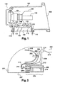
- FIG. 2 shows a device 200 in vertical section, which is composed in particular of an element projector 201 and an additional module 202 of the HID ballast type, which may in particular include an electronic control card 216.
- a reflector 212 in which a light source 203, of the type, has been placed discharge lamp.
- the light source 203 produces a light beam which exits from the projector element 201 at an outlet surface 208, which constitutes the front part of the projector element 201.
- the source luminous 203 which rests on a lamp holder element 204, is connected to a high voltage module 205 used to supply it.
- a recess 206 is, for example, formed in at least one part of a lower surface 207 and part 209 of a rear surface 208 of the projector element 201, the orientations of these surfaces being defined by considering the projector device in a position of usual operation on a motor vehicle, the outlet surface of the light beam constituting the front face of the projector element.
- the headlamp device 200 an attempt has been made to limit the space associated with the addition of the additional ballast-type module 202.
- a single connector 210 as shown in FIG. 2, on the rear part 209 of the headlamp element 201 which is situated at the level of the recess 206.
- the junction of the connector 210 with an appropriate contact area of the complementary module can thus be done in a vertical plane, said contact plane or junction plane, that is to say by moving the ballast 202 in a horizontal direction towards the projector element 201, and no longer in a vertical direction as was the case in the example described in the figure 1.
- the overall height of a projector device comprising an additional module advantageously decreases.
- the recess 206 is slightly extended horizontally, that is to say that it advances a little more under the reflector 212.
- the invention proposes a shielding device involving in particular a connector, to which are connected on the one hand, a link carrying slightly disturbing signals in term of electromagnetic radiation, and on the other hand a bond conveying signals radiating enough to disturb signals neighbors, said connector providing shielding, in terms of radiation electromagnetic, from the second connection to the level of its contacts arranged in the connector.
- the invention essentially refers to an arrangement of the additional module 202 as shown in the Figure 2, it is directly applicable to all devices projectors fitted with an additional module intended to be combined with a spotlight element, and for which the electrical connection between these two elements are carried out by means of a single connector.
- the electronic card can be directly built into the partially shielded connector, i.e. it has a set of contact areas on its surface which are directly accessible by different contact areas of the connector when the electronic card is fitted into the connector. In this case, it is not essential to shield the different contact areas of the electronic card.
- the invention therefore essentially relates to a projector device comprising at least one additional module receiving a set of signals via a first electrical connection, and a projector element comprising at least one disturbance generating element electromagnetic, each element generating disturbances electromagnetic being supplied via an additional electrical connection separate, the first electrical connection and each electrical connection complementary being connected to a single connector, characterized in that the connector comprises a first set of contact zones of the first electrical connection and at least one set of contact zones complementary, each set of complementary contact areas being intended to receive one of the complementary electrical connections, only the set of complementary contact zones being surrounded separately by an electromagnetic shielding element.
- Another object of the invention is a motor vehicle equipped with a projector device, having the main characteristics which have been specified, possibly with at least one of the characteristics just mentioned.
- the embodiment of the invention illustrated in the figures shows a projector device in which the element electromagnetic disturbance generator is a light source. More generally, the invention relates to all of the devices headlamps comprising a disturbance generating element electromagnetic, whether the latter is a light source, a motor or any other element involved in the context of a projector device and requiring the presence of shielding.
- the embodiment of the invention illustrated in the figures shows a projector device in which the number of elements is limited electromagnetic interference generators at the single source bright, but the example illustrated is easily generalizable to a device headlamp comprising several elements generating disturbances electromagnetic, each of these elements then being the subject of a separate electromagnetic shielding especially at the connector unique.
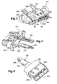
- the connector 210 is shown in perspective, respectively seen from the front and seen from behind, as proposed in the shielding device according to the invention. They are also described in reference to FIG. 5, which is a representation of an element of the connector 210, which is used more particularly in the shielding according to the invention.
- the connector 210 is delimited by a box in plastic 300 having openings on its front face and its rear face.
- the first link 213, which was already visible in Figure 2 is shown in the form of two cylindrical wires, each of the wires carrying a set of particular electrical signals, which enter the connector at its rear side. These two wires carry in particular power signals from the vehicle battery and different control signals for the operation of the add-on 202. These signals are low voltage signals whose amplitude corresponds to that of the vehicle battery. Their influence electromagnetic is therefore weak and does not cause interference on neighboring electrical connections. Electromagnetic shielding of this link is therefore not necessary.
- the two wires 213 are terminated by a first set of zones of contact 301 accessible from the front face of connector 210.
- the zones contacts are arranged in a first set of cavities 302 formed directly in the plastic housing 300. These areas of contact are intended to be affected by associated contact areas present in add-on 202.
- a second set of contact areas 303 is disposed in a second cavity assembly 304.
- the second set of cavities 304 can either be directly housed in the plastic housing 300, or in a plastic part intermediate 305.
- a shielding element 306 is incorporated into the thickness of the plastic case 300 so as to surround laterally the second set of contact zones and the culmination a second set of conducting wires 308 constituting a connection complementary electric, designated in the example illustrated as second electrical connection 215, which is a shielded harness, already visible in FIG. 2.
- the shielding element 306 more particularly visible in FIG. 5, surrounds the intermediate plastic part 305.
- the exemplary embodiment corresponding to the second case has the advantage that the shielded beam 215 is removable; it can easily be removed in its entirety from the housing in plastic 300.
- shielding elements are provided, of the type of the shielding element 306, each of the shielding elements being removable independently of other shielding elements.
- the structure and connections of the different shielding elements, when several are arranged in the plastic housing 300 are identical to those described for the shielding element 306.
- Each of the shielding elements can be removed separately from the plastic housing 300. It can also be provided that certain only of these shielding elements are removable, and not all.
- the shielding element 306 can for example be composed of two half metal shells 307-a and 307-b which are cut and stamped so as to seal the shielding at the level of the second set of contact zones 303.
- the shielding element is made of a single metal cut piece and folded to seal the shield. It has two conductive connecting elements of the spring type, which will ensure the shielding continuity between shielding means 306 and the module complementary 202
- the shielded bundle 215 can consist either of a shielded cable, either by a braid or metallic sheath which surrounds, over their entire length, the second set of conducting wires 308. This is typically composed of three wires supplying the light source; in one first example, a first wire being brought to a potential of about 600 volts, a second wire being brought to a potential of about -400 volts, and the last having zero potential; in a second example, corresponding to the case where the additional module includes a low voltage motor, the potentials observed are of the order of plus or minus 12 volts.
- the electrical characteristics of the signals conducted in these conductive wires require shielding to avoid interference electromagnetic on the first conductive link 213 for example.
- the metallic braid or the shielded cable constituting the shielded bundle 215 is, in an exemplary embodiment, fixed to the shielding element 306 by means a ferrule 309.
- the different contact areas 301 and 303 shown include feelers; a probe is a compound electrical connection element one or more metallic tab type conductive elements, slightly deformable to let a support slide without too much resistance, comprising a set of contact zones, in an opening in which said probe is disposed; the deformation of the probe is elastic from so that it remains supported on the support area at which it is located, said zone preferably corresponding to a contact zone of support.
- the contact zones 301 and 303 are therefore particularly adapted to receive contact areas directly arranged on the area of the electronic card 216 contained in the electronic module 202. The contact areas of the electronic card 216 are thus inserted directly in the various cavities 302 and 304. It is then not essential to provide a special shielding device on the side of the electronic module 202.
- the add-on 202 connects to connector 210 by means of a counterpart of connector
- the contact element is extended 306 out of the housing 300 so that it surrounds the contact areas to shield of the connector counterpart when the latter receives the connector 210.
- means can be provided ensuring continuity electrical between the shielding means (306) and the additional module (202), in particular elastic means of the spring type.
Landscapes
- Engineering & Computer Science (AREA)
- Mechanical Engineering (AREA)
- General Engineering & Computer Science (AREA)
- Details Of Connecting Devices For Male And Female Coupling (AREA)
- Non-Portable Lighting Devices Or Systems Thereof (AREA)
- Arrangement Of Elements, Cooling, Sealing, Or The Like Of Lighting Devices (AREA)
- Lighting Device Outwards From Vehicle And Optical Signal (AREA)
- Shielding Devices Or Components To Electric Or Magnetic Fields (AREA)
Applications Claiming Priority (2)
| Application Number | Priority Date | Filing Date | Title |
|---|---|---|---|
| FR0303212 | 2003-03-14 | ||
| FR0303212A FR2852381B1 (fr) | 2003-03-14 | 2003-03-14 | Dispositif de blindage pour une connexion entre un projecteur et un module complementaire |
Publications (3)
| Publication Number | Publication Date |
|---|---|
| EP1458061A2 true EP1458061A2 (de) | 2004-09-15 |
| EP1458061A3 EP1458061A3 (de) | 2007-10-03 |
| EP1458061B1 EP1458061B1 (de) | 2011-01-05 |
Family
ID=32749802
Family Applications (1)
| Application Number | Title | Priority Date | Filing Date |
|---|---|---|---|
| EP04290551A Expired - Lifetime EP1458061B1 (de) | 2003-03-14 | 2004-03-01 | Abschirmvorrichtung für eine Verbindung zwischen einem Scheinwerfer und einem komplimentären Modul |
Country Status (6)
| Country | Link |
|---|---|
| US (1) | US6916204B2 (de) |
| EP (1) | EP1458061B1 (de) |
| JP (1) | JP4484550B2 (de) |
| AT (1) | ATE494647T1 (de) |
| DE (1) | DE602004030846D1 (de) |
| FR (1) | FR2852381B1 (de) |
Cited By (1)
| Publication number | Priority date | Publication date | Assignee | Title |
|---|---|---|---|---|
| EP1602879A3 (de) * | 2004-06-05 | 2007-11-28 | Hella KGaA Hueck & Co. | Scheinwerfer für Fahrzeuge mit abgeschirmeten Gehäuse für die Vorschalteinrichtung der Gasentladungslampe |
Families Citing this family (9)
| Publication number | Priority date | Publication date | Assignee | Title |
|---|---|---|---|---|
| FR2850729B1 (fr) * | 2003-02-04 | 2006-03-17 | Valeo Vision | Dispositif projecteur equipe d'un module complementaire encastrable pour vehicule automobile |
| FR2869388B1 (fr) * | 2004-04-27 | 2006-09-01 | Valeo Vision Sa | Dispositif projecteur avec bloc actionneur multifonctions pour vehicule automobile |
| FR2872961A1 (fr) * | 2004-07-09 | 2006-01-13 | Valeo Vision Sa | Connecteur d'extremite de faisceau electrique |
| FR2922714B1 (fr) * | 2007-10-19 | 2010-03-12 | Valeo Vision | Dispositif d'alimentation electrique pour une lampe a decharge comportant un blindage de ballast et un blindage de faisceau raccordes en parllele a un potentiel commun |
| US7950836B2 (en) * | 2008-05-09 | 2011-05-31 | Osram Sylvania Inc. | EMI controlled integral HID reflector lamp |
| US20090289553A1 (en) * | 2008-05-23 | 2009-11-26 | Osram Sylvania, Inc. | Integrated ceramic metal halide high frequency ballast assembly |
| US8581482B2 (en) * | 2009-04-30 | 2013-11-12 | Osram Sylvania Inc. | PAR lamp and method of making same |
| DE102011117085A1 (de) * | 2011-10-27 | 2013-05-02 | Md Elektronik Gmbh | Bordnetzkomponente für ein Datenübertragungssystem in einem Kraftfahrzeug |
| FR3044833A1 (fr) * | 2015-12-07 | 2017-06-09 | Valeo Vision | Module de connexion pour vehicule automobile |
Family Cites Families (45)
| Publication number | Priority date | Publication date | Assignee | Title |
|---|---|---|---|---|
| US4674015A (en) * | 1986-05-05 | 1987-06-16 | Smith Daniel R | Fluorescent light fixture with removable ballast |
| US5198962A (en) * | 1989-08-03 | 1993-03-30 | Tyson Glenn M | Lighting system |
| JP2592005B2 (ja) * | 1990-05-18 | 1997-03-19 | 株式会社小糸製作所 | 車輌用前照灯 |
| GB2249825B (en) * | 1990-10-15 | 1994-06-22 | Koito Mfg Co Ltd | Vehicular headlamp |
| US5343370A (en) * | 1990-10-23 | 1994-08-30 | Koito Manufacturing Co., Ltd. | Motor vehicle headlamp |
| JP2768870B2 (ja) * | 1991-08-05 | 1998-06-25 | 株式会社小糸製作所 | バラスト回路と点灯回路間のコード接続構造 |
| US5107405A (en) * | 1991-08-20 | 1992-04-21 | Koito Manufacturing Co., Ltd. | Motor vehicle headlamp |
| DE4133002C3 (de) | 1991-10-04 | 1996-02-15 | Bayerische Motoren Werke Ag | Befestigungsvorrichtung für eine Kraftfahrzeug-Scheinwerfer-Baueinheit |
| DE4310307B4 (de) * | 1993-03-30 | 2004-10-14 | Robert Bosch Gmbh | Scheinwerfer für Fahrzeuge |
| JP2772323B2 (ja) * | 1993-04-28 | 1998-07-02 | 矢崎総業株式会社 | シールドコネクタ用端子およびシールドコネクタ |
| DE4334721B4 (de) * | 1993-10-12 | 2005-06-23 | Automotive Lighting Reutlingen Gmbh | Scheinwerfer für Fahrzeuge |
| JP2828584B2 (ja) * | 1993-12-27 | 1998-11-25 | 株式会社小糸製作所 | 自動車用ヘッドランプ |
| JP3062912B2 (ja) * | 1994-04-26 | 2000-07-12 | 株式会社小糸製作所 | 車輌用灯具 |
| JP3010518B2 (ja) * | 1994-06-28 | 2000-02-21 | 株式会社小糸製作所 | 車輌用前照灯 |
| DE4445223A1 (de) * | 1994-12-17 | 1996-06-20 | Bosch Gmbh Robert | Scheinwerfer für Fahrzeuge |
| JP3061248B2 (ja) * | 1995-01-20 | 2000-07-10 | 株式会社小糸製作所 | 自動車用ヘッドランプ |
| JPH09129379A (ja) * | 1995-11-06 | 1997-05-16 | Koito Mfg Co Ltd | 放電灯点灯装置 |
| JP3195215B2 (ja) * | 1995-12-28 | 2001-08-06 | 株式会社小糸製作所 | 自動車用ヘッドランプ |
| US5879073A (en) * | 1996-01-29 | 1999-03-09 | Koito Manufacturing Co., Ltd. | Vehicular lamp having discharge bulb |
| JP3159078B2 (ja) * | 1996-08-30 | 2001-04-23 | 株式会社デンソー | 高圧放電灯装置 |
| DE19649722A1 (de) * | 1996-11-30 | 1998-06-04 | Reitter & Schefenacker Gmbh | Heckleuchte für Kraftfahrzeuge |
| JPH10261301A (ja) * | 1997-01-16 | 1998-09-29 | Honda Motor Co Ltd | 車両用前照灯 |
| JPH10208505A (ja) * | 1997-01-24 | 1998-08-07 | Koito Mfg Co Ltd | 車輌用前照灯 |
| FR2769072B1 (fr) * | 1997-09-26 | 1999-12-24 | Valeo Vision | Projecteur de vehicule automobile equipe d'une lampe a decharge et de moyens perfectionnes de blindage electromagnetique |
| JP3737295B2 (ja) * | 1997-11-11 | 2006-01-18 | 株式会社小糸製作所 | 車両用前照灯 |
| US6043614A (en) * | 1998-03-06 | 2000-03-28 | Osram Sylvania Inc. | Alternating current hid lamp with magnetic deflection |
| FR2783593B1 (fr) * | 1998-09-21 | 2000-12-29 | Valeo Vision | Projecteur de vehicule automobile equipe d'une lampe a decharge et de moyens perfectionnes de blindage electromagnetique |
| US6102550A (en) * | 1999-02-16 | 2000-08-15 | Photronix, Llc | Bracket assembly for fluorescent lighting fixture having removable, high-frequency power output ballast |
| JP3854421B2 (ja) * | 1999-02-23 | 2006-12-06 | 株式会社小糸製作所 | 放電バルブを有する車両用灯具 |
| JP2000251511A (ja) * | 1999-03-03 | 2000-09-14 | Koito Mfg Co Ltd | 車両用灯具 |
| FR2795691B1 (fr) * | 1999-07-02 | 2001-08-17 | Valeo Vision | Projecteur de vehicule automobile equipe d'une lampe a decharge et de moyens de blindage electromagnetique perfectionnes |
| DE19941538A1 (de) * | 1999-09-01 | 2001-03-15 | Hella Kg Hueck & Co | Gerät zur Aufnahme einer Gasentladungslampe eines Fahrzeug-Scheinwerfers |
| EP1598592B1 (de) | 1999-09-30 | 2008-07-23 | Matsushita Electric Works, Ltd. | Beleuchtungseinrichtung |
| JP3720224B2 (ja) * | 1999-10-19 | 2005-11-24 | 株式会社小糸製作所 | 車両用前照灯 |
| AU2001278022A1 (en) | 2000-08-01 | 2002-02-13 | Osram Sylvania Inc. | Aperture lamp, aperture lamp housing and aperture lamp assembly |
| DE10193456T1 (de) * | 2000-08-18 | 2002-10-24 | Mitsubishi Electric Corp | Abgeschirmter Draht, Verfahren zur Herstellung eines abgeschirmten Drahtes und Leuchtvorrichtung für eine Entladungslampe, welche den abgeschirmten Draht verwendet |
| JP2002150830A (ja) * | 2000-11-07 | 2002-05-24 | Denso Corp | 放電灯装置 |
| JP2002170407A (ja) * | 2000-12-01 | 2002-06-14 | Koito Mfg Co Ltd | 車両用前照灯 |
| JP3928691B2 (ja) * | 2000-12-06 | 2007-06-13 | 株式会社小糸製作所 | 車輌用前照灯 |
| FR2826099B1 (fr) * | 2001-06-18 | 2003-12-19 | Valeo Vision | Dispositif d'eclairage ou de signalisation d'aspect ameliore pour vehicule automobile |
| US6672747B2 (en) * | 2001-08-07 | 2004-01-06 | Denso Corporation | Vehicle headlamp having removable lighting control unit |
| JP3931092B2 (ja) * | 2002-02-08 | 2007-06-13 | 株式会社小糸製作所 | 車輌用前照灯 |
| JP4000269B2 (ja) * | 2002-03-22 | 2007-10-31 | 株式会社小糸製作所 | 車輌用前照灯 |
| FR2843445B1 (fr) * | 2002-08-08 | 2005-05-27 | Valeo Vision | Dispositif projecteur equipe d'un module complementaire pour vehicule automobile |
| FR2850729B1 (fr) * | 2003-02-04 | 2006-03-17 | Valeo Vision | Dispositif projecteur equipe d'un module complementaire encastrable pour vehicule automobile |
-
2003
- 2003-03-14 FR FR0303212A patent/FR2852381B1/fr not_active Expired - Lifetime
-
2004
- 2004-03-01 AT AT04290551T patent/ATE494647T1/de not_active IP Right Cessation
- 2004-03-01 DE DE602004030846T patent/DE602004030846D1/de not_active Expired - Lifetime
- 2004-03-01 EP EP04290551A patent/EP1458061B1/de not_active Expired - Lifetime
- 2004-03-09 JP JP2004065836A patent/JP4484550B2/ja not_active Expired - Lifetime
- 2004-03-11 US US10/799,478 patent/US6916204B2/en not_active Expired - Lifetime
Cited By (1)
| Publication number | Priority date | Publication date | Assignee | Title |
|---|---|---|---|---|
| EP1602879A3 (de) * | 2004-06-05 | 2007-11-28 | Hella KGaA Hueck & Co. | Scheinwerfer für Fahrzeuge mit abgeschirmeten Gehäuse für die Vorschalteinrichtung der Gasentladungslampe |
Also Published As
| Publication number | Publication date |
|---|---|
| FR2852381B1 (fr) | 2005-05-27 |
| FR2852381A1 (fr) | 2004-09-17 |
| JP4484550B2 (ja) | 2010-06-16 |
| DE602004030846D1 (de) | 2011-02-17 |
| JP2004281395A (ja) | 2004-10-07 |
| US20040180578A1 (en) | 2004-09-16 |
| US6916204B2 (en) | 2005-07-12 |
| EP1458061B1 (de) | 2011-01-05 |
| EP1458061A3 (de) | 2007-10-03 |
| ATE494647T1 (de) | 2011-01-15 |
Similar Documents
| Publication | Publication Date | Title |
|---|---|---|
| EP0905441B1 (de) | Kraftfahrzeugscheinwerfer mit einer Entladungslampe und einer verbesserten, elektromagnetischen Abschirmung | |
| EP1458061B1 (de) | Abschirmvorrichtung für eine Verbindung zwischen einem Scheinwerfer und einem komplimentären Modul | |
| FR3056702B1 (fr) | Module lumineux avec dispositif de pilotage integre | |
| EP1388711B1 (de) | Beleuchtungs- oder Signalleuchte mit Zusatzmodul für Kraftfahrzeug | |
| FR2662122A1 (fr) | Systeme de projecteur orientable pour vehicule. | |
| EP0430792B1 (de) | Verbesserung für Multiplex-Steuergeräte für eine Anordnung elektrischer Elemente in einem Kraftfahrzeug | |
| EP1445533B1 (de) | Beleuchtungs- oder Signalisierungsvorrichtung für Kraftfahrzeug mit Einbau-Zusatzmodul | |
| EP1065438A1 (de) | Kfz-Scheinwerfer mit einer Gasentladungslampe und einer verbesserten, elektromagnetischen Abschirmung | |
| EP1839946B1 (de) | Beleuchtungsvorrichtung für elektrischen Zigarrenanzünder oder multi-funktionelle elektrische Steckdose | |
| FR2704937A1 (fr) | Dispositif d'éclairage ou de signalisation à lampe haute tension et à moyens de blindage, pour véhicule automobile. | |
| EP1516777B1 (de) | Beleuchtungsvorrichtung für elektrischen Zigarrenanzünder oder multi-funktionelle elektrische Steckdose | |
| EP1030998B1 (de) | Kraftfahrzeugscheinwerfer mit einer lampe und einer verbesserten, elektromagnetischen abschirmung | |
| FR2742709A1 (fr) | Phare pour vehicule avec reflecteur | |
| FR2835595A1 (fr) | Douille de lampe pour projecteur de vehicule automobile, et reflecteur de projecteur destine a recevoir une telle douille de lampe. | |
| FR2793871A1 (fr) | Projecteur de vehicule automobile equipe de moyens perfectionnes pour reduire les phenomenes de condensation | |
| FR2710131A1 (fr) | Ensemble connecteur et générateur à haute tension pour une lampe à décharge de véhicule automobile. | |
| EP0898113B1 (de) | Scheinwerfer mit Gasentladungslampe | |
| FR2685439A1 (fr) | Projecteur de vehicule automobile presentant une disposition de circuit electronique perfectionnee. | |
| FR2493471A1 (fr) | Dispositif d'eclairage electrique a mecanisme de support d'ampoule du type barrettes | |
| FR2842479A1 (fr) | Dispositif projecteur avec carte de controle electronique pour vehicule automobile | |
| FR2717982A1 (fr) | Dispositif de blindage électromagnétique de systèmes d'éclairage et/ou de signalisation de véhicule du type lampe à décharge tubulaire. | |
| EP1398563A1 (de) | Positionierungs- und Versorgungsmodul für Leuchtdiode | |
| EP2051574A1 (de) | Vorrichtung zur Stromversorgung einer Leuchtstofflampe, die eine Abschirmung des Vorschaltgeräts umfasst | |
| FR2835593A1 (fr) | Douille de lampe pour projecteur de vehicule automobile, et reflecteur de projecteur destine a recevoir une telle douille de lampe | |
| FR2596499A1 (fr) | Feu de signalisation a reflecteur complexe pour vehicule automobile |
Legal Events
| Date | Code | Title | Description |
|---|---|---|---|
| PUAI | Public reference made under article 153(3) epc to a published international application that has entered the european phase |
Free format text: ORIGINAL CODE: 0009012 |
|
| AK | Designated contracting states |
Kind code of ref document: A2 Designated state(s): AT BE BG CH CY CZ DE DK EE ES FI FR GB GR HU IE IT LI LU MC NL PL PT RO SE SI SK TR |
|
| AX | Request for extension of the european patent |
Extension state: AL HR LT LV MK |
|
| PUAL | Search report despatched |
Free format text: ORIGINAL CODE: 0009013 |
|
| AK | Designated contracting states |
Kind code of ref document: A3 Designated state(s): AT BE BG CH CY CZ DE DK EE ES FI FR GB GR HU IE IT LI LU MC NL PL PT RO SE SI SK TR |
|
| AX | Request for extension of the european patent |
Extension state: AL LT LV MK |
|
| RIC1 | Information provided on ipc code assigned before grant |
Ipc: H01R 13/658 20060101AFI20040708BHEP Ipc: F21V 19/00 20060101ALI20070830BHEP |
|
| 17P | Request for examination filed |
Effective date: 20080312 |
|
| AKX | Designation fees paid |
Designated state(s): AT BE BG CH CY CZ DE DK EE ES FI FR GB GR HU IE IT LI LU MC NL PL PT RO SE SI SK TR |
|
| GRAP | Despatch of communication of intention to grant a patent |
Free format text: ORIGINAL CODE: EPIDOSNIGR1 |
|
| GRAS | Grant fee paid |
Free format text: ORIGINAL CODE: EPIDOSNIGR3 |
|
| GRAA | (expected) grant |
Free format text: ORIGINAL CODE: 0009210 |
|
| AK | Designated contracting states |
Kind code of ref document: B1 Designated state(s): AT BE BG CH CY CZ DE DK EE ES FI FR GB GR HU IE IT LI LU MC NL PL PT RO SE SI SK TR |
|
| REG | Reference to a national code |
Ref country code: GB Ref legal event code: FG4D Free format text: NOT ENGLISH |
|
| REG | Reference to a national code |
Ref country code: CH Ref legal event code: EP |
|
| REG | Reference to a national code |
Ref country code: IE Ref legal event code: FG4D Free format text: LANGUAGE OF EP DOCUMENT: FRENCH |
|
| REF | Corresponds to: |
Ref document number: 602004030846 Country of ref document: DE Date of ref document: 20110217 Kind code of ref document: P |
|
| REG | Reference to a national code |
Ref country code: DE Ref legal event code: R096 Ref document number: 602004030846 Country of ref document: DE Effective date: 20110217 |
|
| REG | Reference to a national code |
Ref country code: NL Ref legal event code: T3 |
|
| PG25 | Lapsed in a contracting state [announced via postgrant information from national office to epo] |
Ref country code: SI Free format text: LAPSE BECAUSE OF FAILURE TO SUBMIT A TRANSLATION OF THE DESCRIPTION OR TO PAY THE FEE WITHIN THE PRESCRIBED TIME-LIMIT Effective date: 20110105 |
|
| PG25 | Lapsed in a contracting state [announced via postgrant information from national office to epo] |
Ref country code: ES Free format text: LAPSE BECAUSE OF FAILURE TO SUBMIT A TRANSLATION OF THE DESCRIPTION OR TO PAY THE FEE WITHIN THE PRESCRIBED TIME-LIMIT Effective date: 20110416 Ref country code: GR Free format text: LAPSE BECAUSE OF FAILURE TO SUBMIT A TRANSLATION OF THE DESCRIPTION OR TO PAY THE FEE WITHIN THE PRESCRIBED TIME-LIMIT Effective date: 20110406 Ref country code: SE Free format text: LAPSE BECAUSE OF FAILURE TO SUBMIT A TRANSLATION OF THE DESCRIPTION OR TO PAY THE FEE WITHIN THE PRESCRIBED TIME-LIMIT Effective date: 20110105 Ref country code: PT Free format text: LAPSE BECAUSE OF FAILURE TO SUBMIT A TRANSLATION OF THE DESCRIPTION OR TO PAY THE FEE WITHIN THE PRESCRIBED TIME-LIMIT Effective date: 20110505 |
|
| PGFP | Annual fee paid to national office [announced via postgrant information from national office to epo] |
Ref country code: ES Payment date: 20110321 Year of fee payment: 8 Ref country code: GB Payment date: 20110222 Year of fee payment: 8 |
|
| REG | Reference to a national code |
Ref country code: IE Ref legal event code: FD4D |
|
| PG25 | Lapsed in a contracting state [announced via postgrant information from national office to epo] |
Ref country code: BG Free format text: LAPSE BECAUSE OF FAILURE TO SUBMIT A TRANSLATION OF THE DESCRIPTION OR TO PAY THE FEE WITHIN THE PRESCRIBED TIME-LIMIT Effective date: 20110405 Ref country code: AT Free format text: LAPSE BECAUSE OF FAILURE TO SUBMIT A TRANSLATION OF THE DESCRIPTION OR TO PAY THE FEE WITHIN THE PRESCRIBED TIME-LIMIT Effective date: 20110105 Ref country code: CY Free format text: LAPSE BECAUSE OF FAILURE TO SUBMIT A TRANSLATION OF THE DESCRIPTION OR TO PAY THE FEE WITHIN THE PRESCRIBED TIME-LIMIT Effective date: 20110105 Ref country code: FI Free format text: LAPSE BECAUSE OF FAILURE TO SUBMIT A TRANSLATION OF THE DESCRIPTION OR TO PAY THE FEE WITHIN THE PRESCRIBED TIME-LIMIT Effective date: 20110105 Ref country code: PL Free format text: LAPSE BECAUSE OF FAILURE TO SUBMIT A TRANSLATION OF THE DESCRIPTION OR TO PAY THE FEE WITHIN THE PRESCRIBED TIME-LIMIT Effective date: 20110105 |
|
| PG25 | Lapsed in a contracting state [announced via postgrant information from national office to epo] |
Ref country code: EE Free format text: LAPSE BECAUSE OF FAILURE TO SUBMIT A TRANSLATION OF THE DESCRIPTION OR TO PAY THE FEE WITHIN THE PRESCRIBED TIME-LIMIT Effective date: 20110105 Ref country code: DK Free format text: LAPSE BECAUSE OF FAILURE TO SUBMIT A TRANSLATION OF THE DESCRIPTION OR TO PAY THE FEE WITHIN THE PRESCRIBED TIME-LIMIT Effective date: 20110105 Ref country code: IE Free format text: LAPSE BECAUSE OF FAILURE TO SUBMIT A TRANSLATION OF THE DESCRIPTION OR TO PAY THE FEE WITHIN THE PRESCRIBED TIME-LIMIT Effective date: 20110105 Ref country code: MC Free format text: LAPSE BECAUSE OF NON-PAYMENT OF DUE FEES Effective date: 20110331 |
|
| REG | Reference to a national code |
Ref country code: CH Ref legal event code: PL |
|
| PLBE | No opposition filed within time limit |
Free format text: ORIGINAL CODE: 0009261 |
|
| STAA | Information on the status of an ep patent application or granted ep patent |
Free format text: STATUS: NO OPPOSITION FILED WITHIN TIME LIMIT |
|
| PG25 | Lapsed in a contracting state [announced via postgrant information from national office to epo] |
Ref country code: RO Free format text: LAPSE BECAUSE OF FAILURE TO SUBMIT A TRANSLATION OF THE DESCRIPTION OR TO PAY THE FEE WITHIN THE PRESCRIBED TIME-LIMIT Effective date: 20110105 Ref country code: SK Free format text: LAPSE BECAUSE OF FAILURE TO SUBMIT A TRANSLATION OF THE DESCRIPTION OR TO PAY THE FEE WITHIN THE PRESCRIBED TIME-LIMIT Effective date: 20110105 Ref country code: CZ Free format text: LAPSE BECAUSE OF FAILURE TO SUBMIT A TRANSLATION OF THE DESCRIPTION OR TO PAY THE FEE WITHIN THE PRESCRIBED TIME-LIMIT Effective date: 20110105 |
|
| 26N | No opposition filed |
Effective date: 20111006 |
|
| PG25 | Lapsed in a contracting state [announced via postgrant information from national office to epo] |
Ref country code: IT Free format text: LAPSE BECAUSE OF FAILURE TO SUBMIT A TRANSLATION OF THE DESCRIPTION OR TO PAY THE FEE WITHIN THE PRESCRIBED TIME-LIMIT Effective date: 20110105 |
|
| PG25 | Lapsed in a contracting state [announced via postgrant information from national office to epo] |
Ref country code: CH Free format text: LAPSE BECAUSE OF NON-PAYMENT OF DUE FEES Effective date: 20110331 Ref country code: LI Free format text: LAPSE BECAUSE OF NON-PAYMENT OF DUE FEES Effective date: 20110331 |
|
| REG | Reference to a national code |
Ref country code: DE Ref legal event code: R097 Ref document number: 602004030846 Country of ref document: DE Effective date: 20111006 |
|
| GBPC | Gb: european patent ceased through non-payment of renewal fee |
Effective date: 20120301 |
|
| PG25 | Lapsed in a contracting state [announced via postgrant information from national office to epo] |
Ref country code: GB Free format text: LAPSE BECAUSE OF NON-PAYMENT OF DUE FEES Effective date: 20120301 |
|
| PG25 | Lapsed in a contracting state [announced via postgrant information from national office to epo] |
Ref country code: LU Free format text: LAPSE BECAUSE OF NON-PAYMENT OF DUE FEES Effective date: 20110301 |
|
| PG25 | Lapsed in a contracting state [announced via postgrant information from national office to epo] |
Ref country code: TR Free format text: LAPSE BECAUSE OF FAILURE TO SUBMIT A TRANSLATION OF THE DESCRIPTION OR TO PAY THE FEE WITHIN THE PRESCRIBED TIME-LIMIT Effective date: 20110105 |
|
| PG25 | Lapsed in a contracting state [announced via postgrant information from national office to epo] |
Ref country code: HU Free format text: LAPSE BECAUSE OF FAILURE TO SUBMIT A TRANSLATION OF THE DESCRIPTION OR TO PAY THE FEE WITHIN THE PRESCRIBED TIME-LIMIT Effective date: 20110105 |
|
| REG | Reference to a national code |
Ref country code: FR Ref legal event code: PLFP Year of fee payment: 13 |
|
| REG | Reference to a national code |
Ref country code: FR Ref legal event code: PLFP Year of fee payment: 14 |
|
| REG | Reference to a national code |
Ref country code: FR Ref legal event code: PLFP Year of fee payment: 15 |
|
| PGFP | Annual fee paid to national office [announced via postgrant information from national office to epo] |
Ref country code: NL Payment date: 20200227 Year of fee payment: 17 Ref country code: DE Payment date: 20200311 Year of fee payment: 17 |
|
| PGFP | Annual fee paid to national office [announced via postgrant information from national office to epo] |
Ref country code: BE Payment date: 20200330 Year of fee payment: 17 |
|
| PGFP | Annual fee paid to national office [announced via postgrant information from national office to epo] |
Ref country code: FR Payment date: 20200331 Year of fee payment: 17 |
|
| REG | Reference to a national code |
Ref country code: DE Ref legal event code: R119 Ref document number: 602004030846 Country of ref document: DE |
|
| REG | Reference to a national code |
Ref country code: NL Ref legal event code: MM Effective date: 20210401 |
|
| REG | Reference to a national code |
Ref country code: BE Ref legal event code: MM Effective date: 20210331 |
|
| PG25 | Lapsed in a contracting state [announced via postgrant information from national office to epo] |
Ref country code: NL Free format text: LAPSE BECAUSE OF NON-PAYMENT OF DUE FEES Effective date: 20210401 Ref country code: FR Free format text: LAPSE BECAUSE OF NON-PAYMENT OF DUE FEES Effective date: 20210331 Ref country code: DE Free format text: LAPSE BECAUSE OF NON-PAYMENT OF DUE FEES Effective date: 20211001 |
|
| PG25 | Lapsed in a contracting state [announced via postgrant information from national office to epo] |
Ref country code: BE Free format text: LAPSE BECAUSE OF NON-PAYMENT OF DUE FEES Effective date: 20210331 |