EP1458080B1 - Dynamoelektromotor des permanentmagnettyps und synchrongenerator des permanentmagnettyps zur windenergieerzeugungsbenutzung - Google Patents
Dynamoelektromotor des permanentmagnettyps und synchrongenerator des permanentmagnettyps zur windenergieerzeugungsbenutzung Download PDFInfo
- Publication number
- EP1458080B1 EP1458080B1 EP02790815.1A EP02790815A EP1458080B1 EP 1458080 B1 EP1458080 B1 EP 1458080B1 EP 02790815 A EP02790815 A EP 02790815A EP 1458080 B1 EP1458080 B1 EP 1458080B1
- Authority
- EP
- European Patent Office
- Prior art keywords
- permanent magnet
- rotor
- magnet type
- eddy current
- meet
- Prior art date
- Legal status (The legal status is an assumption and is not a legal conclusion. Google has not performed a legal analysis and makes no representation as to the accuracy of the status listed.)
- Expired - Lifetime
Links
Images






Classifications
-
- H—ELECTRICITY
- H02—GENERATION; CONVERSION OR DISTRIBUTION OF ELECTRIC POWER
- H02K—DYNAMO-ELECTRIC MACHINES
- H02K21/00—Synchronous motors having permanent magnets; Synchronous generators having permanent magnets
- H02K21/12—Synchronous motors having permanent magnets; Synchronous generators having permanent magnets with stationary armatures and rotating magnets
- H02K21/14—Synchronous motors having permanent magnets; Synchronous generators having permanent magnets with stationary armatures and rotating magnets with magnets rotating within the armatures
-
- F—MECHANICAL ENGINEERING; LIGHTING; HEATING; WEAPONS; BLASTING
- F03—MACHINES OR ENGINES FOR LIQUIDS; WIND, SPRING, OR WEIGHT MOTORS; PRODUCING MECHANICAL POWER OR A REACTIVE PROPULSIVE THRUST, NOT OTHERWISE PROVIDED FOR
- F03D—WIND MOTORS
- F03D9/00—Adaptations of wind motors for special use; Combinations of wind motors with apparatus driven thereby; Wind motors specially adapted for installation in particular locations
- F03D9/20—Wind motors characterised by the driven apparatus
- F03D9/25—Wind motors characterised by the driven apparatus the apparatus being an electrical generator
-
- H—ELECTRICITY
- H02—GENERATION; CONVERSION OR DISTRIBUTION OF ELECTRIC POWER
- H02K—DYNAMO-ELECTRIC MACHINES
- H02K21/00—Synchronous motors having permanent magnets; Synchronous generators having permanent magnets
- H02K21/12—Synchronous motors having permanent magnets; Synchronous generators having permanent magnets with stationary armatures and rotating magnets
- H02K21/14—Synchronous motors having permanent magnets; Synchronous generators having permanent magnets with stationary armatures and rotating magnets with magnets rotating within the armatures
- H02K21/16—Synchronous motors having permanent magnets; Synchronous generators having permanent magnets with stationary armatures and rotating magnets with magnets rotating within the armatures having annular armature cores with salient poles
-
- F—MECHANICAL ENGINEERING; LIGHTING; HEATING; WEAPONS; BLASTING
- F05—INDEXING SCHEMES RELATING TO ENGINES OR PUMPS IN VARIOUS SUBCLASSES OF CLASSES F01-F04
- F05B—INDEXING SCHEME RELATING TO WIND, SPRING, WEIGHT, INERTIA OR LIKE MOTORS, TO MACHINES OR ENGINES FOR LIQUIDS COVERED BY SUBCLASSES F03B, F03D AND F03G
- F05B2220/00—Application
- F05B2220/70—Application in combination with
- F05B2220/706—Application in combination with an electrical generator
- F05B2220/7068—Application in combination with an electrical generator equipped with permanent magnets
-
- F—MECHANICAL ENGINEERING; LIGHTING; HEATING; WEAPONS; BLASTING
- F05—INDEXING SCHEMES RELATING TO ENGINES OR PUMPS IN VARIOUS SUBCLASSES OF CLASSES F01-F04
- F05B—INDEXING SCHEME RELATING TO WIND, SPRING, WEIGHT, INERTIA OR LIKE MOTORS, TO MACHINES OR ENGINES FOR LIQUIDS COVERED BY SUBCLASSES F03B, F03D AND F03G
- F05B2240/00—Components
- F05B2240/40—Use of a multiplicity of similar components
-
- F—MECHANICAL ENGINEERING; LIGHTING; HEATING; WEAPONS; BLASTING
- F05—INDEXING SCHEMES RELATING TO ENGINES OR PUMPS IN VARIOUS SUBCLASSES OF CLASSES F01-F04
- F05B—INDEXING SCHEME RELATING TO WIND, SPRING, WEIGHT, INERTIA OR LIKE MOTORS, TO MACHINES OR ENGINES FOR LIQUIDS COVERED BY SUBCLASSES F03B, F03D AND F03G
- F05B2240/00—Components
- F05B2240/50—Bearings
- F05B2240/51—Bearings magnetic
- F05B2240/511—Bearings magnetic with permanent magnets
-
- H—ELECTRICITY
- H02—GENERATION; CONVERSION OR DISTRIBUTION OF ELECTRIC POWER
- H02K—DYNAMO-ELECTRIC MACHINES
- H02K7/00—Arrangements for handling mechanical energy structurally associated with dynamo-electric machines, e.g. structural association with mechanical driving motors or auxiliary dynamo-electric machines
- H02K7/18—Structural association of electric generators with mechanical driving motors, e.g. with turbines
- H02K7/1807—Rotary generators
- H02K7/1823—Rotary generators structurally associated with turbines or similar engines
-
- H—ELECTRICITY
- H02—GENERATION; CONVERSION OR DISTRIBUTION OF ELECTRIC POWER
- H02K—DYNAMO-ELECTRIC MACHINES
- H02K7/00—Arrangements for handling mechanical energy structurally associated with dynamo-electric machines, e.g. structural association with mechanical driving motors or auxiliary dynamo-electric machines
- H02K7/18—Structural association of electric generators with mechanical driving motors, e.g. with turbines
- H02K7/1807—Rotary generators
- H02K7/1823—Rotary generators structurally associated with turbines or similar engines
- H02K7/183—Rotary generators structurally associated with turbines or similar engines wherein the turbine is a wind turbine
-
- H—ELECTRICITY
- H02—GENERATION; CONVERSION OR DISTRIBUTION OF ELECTRIC POWER
- H02K—DYNAMO-ELECTRIC MACHINES
- H02K7/00—Arrangements for handling mechanical energy structurally associated with dynamo-electric machines, e.g. structural association with mechanical driving motors or auxiliary dynamo-electric machines
- H02K7/18—Structural association of electric generators with mechanical driving motors, e.g. with turbines
- H02K7/1807—Rotary generators
- H02K7/1823—Rotary generators structurally associated with turbines or similar engines
- H02K7/183—Rotary generators structurally associated with turbines or similar engines wherein the turbine is a wind turbine
- H02K7/1838—Generators mounted in a nacelle or similar structure of a horizontal axis wind turbine
-
- Y—GENERAL TAGGING OF NEW TECHNOLOGICAL DEVELOPMENTS; GENERAL TAGGING OF CROSS-SECTIONAL TECHNOLOGIES SPANNING OVER SEVERAL SECTIONS OF THE IPC; TECHNICAL SUBJECTS COVERED BY FORMER USPC CROSS-REFERENCE ART COLLECTIONS [XRACs] AND DIGESTS
- Y02—TECHNOLOGIES OR APPLICATIONS FOR MITIGATION OR ADAPTATION AGAINST CLIMATE CHANGE
- Y02E—REDUCTION OF GREENHOUSE GAS [GHG] EMISSIONS, RELATED TO ENERGY GENERATION, TRANSMISSION OR DISTRIBUTION
- Y02E10/00—Energy generation through renewable energy sources
- Y02E10/70—Wind energy
- Y02E10/72—Wind turbines with rotation axis in wind direction
Definitions
- the present invention relates to a permanent magnet type dynamo electric machine, and a permanent magnet type synchronous generator for wind power generation, and more particularly, to a permanent magnet type dynamo electric machine, and a permanent magnet type synchronous generator for wind power generation, each including a rotor having a plurality of magnetic poles composed of permanent magnets, and a stator having armature windings wound around the magnetic poles.
- a so-called permanent magnet type dynamo electric machine with concentrated winding including a rotor having a plurality of magnetic poles composed of permanent magnets, and a stator having armature windings concentratedly wound around the magnetic poles has been used in various applications.
- the concentrated winding has the construction in which the armature windings are concentratedly wound around the magnetic poles of the stator and hence automatic winding by a machine is possible therefor.
- many permanent magnet type dynamo electric machines with concentrated winding are used mainly for small motors such as servo. In such a small motor, a copper loss, a core loss, and a mechanical loss occupy a majority of the losses, and therefore an eddy current loss caused in the rotor does not become a problem in most cases.
- the concentrated winding has a superior advantage in that the coil end is small, and moreover, the automatic winding is possible.
- it has a problem in that an eddy current loss of a rotor due to a magnetomotive force of an armature current becomes larger than that in the distributed winding.
- high performance magnets such as a rare earth magnet, each having a high residual magnetic flux density and a high coercive force, have been positively utilized as magnetic poles of a rotor of a large capacity generator.
- an Nd-Fe-B-basedmagnet has such characteristics as being high in its electric conductivity, thereby allowing an eddy to easily flow as compared with a ferrite-based magnet.
- JP 2001-59271 A there is disclosed a method in which an iron core of a rotor is constructed by a massive yoke instead of a laminated steel plate, and the yoke is partitioned so that a path of the eddy current is cut off, to thereby reduce the eddy current.
- the construction in which a lamination structure is adopted for a yoke of a rotor and the construction in which a massive yoke is partitioned have been proposed.
- the lamination structure is adopted, there is a problem in that the cost becomes higher due to the increase in the processing cost.
- a massive yoke is partitioned, there arises a problem in that fluctuation occurs in the magnetic flux densities of gap portions of a motor, which leads to ununiformity of the electromagnetic force. Consequently, it can be said that the yoke of the rotor is desirably of an integral type.
- the present invention has been made in order to solve the above-mentioned problems associated with the prior art, and it is, therefore, an object of the present invention to obtain a permanent magnet type dynamo electric machine, and a permanent magnet type synchronous generator for wind power generation, each being capable of reducing an eddy current loss of a rotor, while keeping a construction of an integral type for a rotor yoke.
- EP 1 130 747 discloses a permanent magnet type electric rotating machine comprising a stator having a salient-pole concentrated winding, and a rotor disposed with a rotational gap, and having a plurality of permanent magnets arranged and fixed in a circumferential direction inside, and an auxiliary salient pole provided between the permanent magnets.
- a ratio of the number of poles for the rotor and the number of slots for the stator is 2:3.
- An angular relationship is also set.
- GB 2 006 540 A disclose further exemplary electric machines.
- the present invention provides a permanent magnet type machine according to independent claim 1. Further embodiments of the invention may be realised in accordance with the dependent claims.
- examples of the permanent magnet type machine include a permanent magnet type dynamo electric machine and to a permanent magnet type synchronous generator for wind power generation.
- FIG. 1 is a permanent magnet type synchronous generator of an inner rotor type. That is, in Fig. 1 , a stator 101 is positioned outside a rotor 100. In Fig.
- reference numeral 1 designates a stator iron core constituting the stator 101
- reference numeral 2 designates a plurality of teeth provided in the stator iron core 1
- reference numeral 3 designates a slot as a recess portion which is formed between the adjacent teeth 2
- reference numeral 4 designates a plurality of permanent magnets provided in the rotor 100
- reference numeral 5 designates an integral type massive rotor yoke to which the permanent magnets 4 are attached at equal intervals
- reference numeral 6 designates a rotation axis of the rotor 100.
- a rotor outer diameter is 3 m
- the number of permanent magnets 4 provided in the rotor 100 i.e., the number of rotor magnetic poles
- each of the number of teeth 2 of the stator 101 and the number of slots 3 of the stator 101 is 96.
- a surface magnet type synchronous generator is shown, in which the permanent magnets 4 are arranged on the surface of the massive yoke 5 of the rotor 100, and the stator 101 has the 96 teeth 2. While the illustration is omitted in Fig. 1 , a winding system of a so-called concentrated winding is adopted, in which armature wirings are concentratedly wound around the teeth 2.
- Fig. 2(a) schematically shows a part of the stator 101 and the rotor 100 of Fig. 1
- Figs. 2 (b), (c) and (d) show magnetomotive force waveforms each of which is formed by an armature current.
- reference numeral 8 designates the armature windings wound around the teeth 2. Since other constructions correspond to those shown in Fig. 1 , the same constituent elements are designated with the same reference numerals, and the descriptions thereof are omitted here. Since in this embodiment mode, the ratio of the number of poles of the rotor 100 to the number of slots of the stator 101 is 2 : 3, the 2 poles and 3 slots electromagnetically become one unit.
- the armature wirings 8 of a phase U, a phase V and a phase W, i.e., 3 phases in total are accommodated in the slots 3, and these armature windings 8 are concentratedly wound around the teeth 2.
- Sine-wave like currents whose electrical angles are shifted by 120 degrees with one another, are caused to flow through the armature windings 8 of 3 phases, respectively.
- a magnetomotive force having a rectangular waveform is generated in each gap portion.
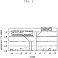
- Fig. 3 shows the results of the Fourier analysis of the magnetomotive force of the stator when the ratio of the number 2P of poles to the number S of slots is 2 : 3.
- the axis of abscissa represents a spatial harmonic order with the 2 poles (its electrical angle is 360 degrees) as a fundamental wave.
- the axis of abscissa represents a magnetomotive force which shows a positive-phase and which is rotated in the same direction as that of the rotor 100.
- the axis of abscissa represents a magnetomotive force which shows an opposite phase and which is rotated in a direction opposite to the rotational direction of the rotor 100.
- the axis of ordinate represents amplitude of a magnetomotive force of a component concerned.
- the component synchronous with the magnetic poles of the rotor 100 is the component of +1-th order on the axis of abscissa, and a torque is obtained by this component.
- this magnetomotive force component is the magnetomotive force which is not changed with time when viewed from the coordinate system fixed to the rotor 100, it does not become a cause of generation of an eddy current of the rotor 100.
- the components other than that magnetomotive force component are the asynchronous components and hence are changed with time when viewed from the coordinate system fixed to the rotor 100, they become the cause of an eddy current of the rotor 100.
- the component of -2-nd order has the largest amplitude.
- the synchronous component (the positive-phase component of a fundamental wave) and the opposite-phase component of 2-nd order as an example of the asynchronous component are shown in Figs. 2(c) and 2(d) , respectively. As has already been described, this synchronous component does not become the cause of an eddy current, while the asynchronous components cause an eddy current in the rotor 100.
- the opposite-phase component of 2-nd order is the main cause of an eddy current loss caused in the rotor 100. Since the number of poles of the generator handled in this embodiment mode is 64, a spatial harmonic order of a waveform of the magnetomotive force becoming the main cause of the eddy current becomes 64-th order if a mechanical angle of 360 degrees are assumed to be 1-st order.
- an eddy current will now be derived approximately using a simple model. Moreover, let us consider what relationship is established among the order N of the asynchronous component of the magnetomotive force to be the cause of the eddy current concerned, the number P of pole pairs of the rotor 100 and an outer diameter D[m] of the rotor 100, and in what manner the above-mentioned N and P should be selected in order to reduce the eddy current.
- An upper stage of Fig. 4 shows a change with elapse of time of a magnetic flux generated with the asynchronous components of the magnetomotive force to be the cause of an eddy current.
- a lower stage of Fig. 4 shows a minute circuit (slant line portion) which is used when a path of an eddy current caused to flow through the rotor 100 due to a change of the magnet flux and an eddy current loss are obtained, and also shows a situation when the rotor 100 is overlooked from a gap surface in a simplified manner. Note that, in Fig.
- reference symbol w[m] designates a length for one period of a magnetomotive force to be the cause of an eddy current, i.e., a wavelength
- reference symbol L[m] designates a core length of the generator.
- reference symbol x designates a coordinate [m] representing a circumferential position
- reference symbol y designates a coordinate [m] representing an axial position.
- the path along which an eddy current is caused to flow is formed within a range of a width for a half wavelength of a magnetomotive force, i.e., a width of w/2.
- a minute circuit is considered in the position, as exhibited by a slant line portion of the figure within the range of w/2, defined by the circumferential width 2x and the axial width 2y, and an eddy current loss is obtained from a resistance of this minute circuit and a magnetomotive force applied to this circuit to be further spatially integrated to thereby calculate the eddy current loss caused in the whole generator.
- K ⁇ 64 + 1 16 ⁇ 2 2 ⁇
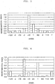
- Fig. 5 shows the results of the Fourier analysis of the magnetomotive force of the stator when the ratio of the number 2P of poles to the number S of slots is 4 : 3
- Fig. 6 shows the results of the Fourier analysis of the magnetomotive force of the stator when the ratio of the number 2P of poles to the number S of slots is 10 : 9
- Fig. 7 shows the results of the Fourier analysis of the magnetomotive force of the stator when the ratio of the number 2P of poles to the number S of slots is 8 : 9
- Fig. 8 shows the results of the Fourier analysis of the magnetomotive force of the stator when the ratio of the number 2P of poles to the number S of slots is 10 : 12.
- the asynchronous components of the magnetomotive force are of 5-th order in positive-phase, and of 7-th order or more in opposite phase. Thus, they are the components of higher order than that of the fundamental wave.
- the order of the asynchronous component is near that of the fundamental wave as compared with the distributed wiring, and an asynchronous component is present even in a component having order lower than that of the fundamental wave in some cases.
- X does not show the rate in the strict sense of the word, it is considered that X is calculated in the various generators or motors to be aware of its magnitude to thereby become a criterion in accordance with which the magnitude of the eddy current loss is judged.
- the design is preferably made so as to meet a relationship of D ⁇ 2.2 [m], more preferably so as to meet a relationship of D ⁇ 2.3 [m], and further more preferably so as to meet a relationship of D ⁇ 2.7 [m].
- the design is preferably made so as to meet a relationship of D ⁇ 1.4 [m], more preferably so as to meet a relationship of D ⁇ 1.5 [m], and further more preferably so as to meet a relationship of D ⁇ 1.8 [m].
- the linear approximation in the range in which the output is small, the approximation does not meet the actual curve.
- the outer diameters are substantially made identical to one another and the axis lengths are adjusted because of limitations of production facility and the like in many cases. From this reason, even in an area in which the output is low, the linear approximation is adopted so as not for an outer diameter to be abruptly decreased. From the foregoing, since even when the output becomes low, an outer diameter is not extremely decreased, such an effect can be obtained that even in the case where the same production facility is adopted, it is possible to manufacture a generator having a low output.
- the copper loss and the core loss can be reduced on the basis of a size, a shape and the like of the stator to some degree, there is a limit thereto. Then, it is considered that if a construction is adopted in which the eddy current loss of the rotor can be reduced down to a half of the total loss 5%, i.e., 2.5%, then the total loss of summing up the losses such as the copper loss and the core loss can be suppressed to about 5%. In other words, it is considered that if the eddy current loss of the rotor can be suppressed to about 2.5% of the rated output, then the high efficiency of 95% can be attained.
- a generator 12 and an accelerating gear 13 are provided in an inside of the nacelle 11, in an example of Fig. 11 , a generator 12 and an accelerating gear 13 are provided, while in an example of Fig. 12 , only the generator 12 is provided.
- Reference numeral 14 designates a wind mill provided in a head of the nacelle 11, and reference numerals 15 and 16 designate a hub and a blade constituting the wind mill 14, respectively.
- the rotor and stator are the same in construction as those of Fig. 1 shown in the above-mentibned embodiment 1, the description thereof is omitted here.
- the nacelle 11 is provided on the tower 10, the generator 12 and the accelerating gear 13 are accommodated in the inside of the nacelle 11, and the wind mill 14 is connected to the head of the nacelle 11.
- the wind mill 14 constituted by the hub 15 and the blade 16, and the generator 12 are connected to each other through the accelerating gear 13.
- the accelerating gear 13 is provided therebetween, whereby the rotational frequency of the generator 12 is made higher than that of the wind mill 14, there is an advantage in that a torque of the generator 12 may be small, and hence the miniaturization of the generator 12 becomes possible.
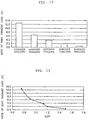
- the widths of slot opening portions were designed substantially equal to one another in order to prevent an influence of a change in permeance of a slot opening portion from being increased. Then, with respect to these five kinds of generators, eddy current losses caused in the rotors during the rated running were found on the basis of the analysis of the electromagnetic field. The rates of the respective eddy current losses to the outputs are shown in Fig. 13 . From these results, it is understood that even if the numbers 2P of poles are designed substantially equal to one another, there is a large difference in eddy current loss depending on the combination of the number of poles and the number of slots.
- a graph in which the ratio S/2P of the number of slots to the number of poles is plotted on the axis of abscissa is shown in Fig. 14 . From these results, it is understood that when S/2P > 1, i.e., 2P ⁇ S, the eddy current is small, conversely when S/2P ⁇ 1, i.e., 2P > S, the eddy current loss is large.
- the magnitude of the eddy current loss of the rotor depends on the spatial harmonic order N of the magnetomotive force from Expression (18). Accordingly, when a large permanent magnet type dynamo electric machine with concentrated winding is designed, it may safely be said that since when a relationship of 2P ⁇ S is adopted, N can be designed so as to be smaller, the eddy current loss becomes less. Of course, even in the case of the condition of 2P > S, if the number of poles is increased to obtain such a construction as to meet Expression (19), then the eddy current loss can be reduced. However, since if the values of the parameter X are intended to be designed so as to be identical to one another, then the number of poles is increased to increase the processing cost, which is disadvantageous as compared with the case where the condition of 2P ⁇ S is adopted.
- both the least common multiples are 192
- the least common multiple is 576
- the least common multiple is 360.
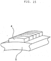
- This embodiment mode is shown in Fig. 15 .
- a construction is adopted as shown in Fig. 15 in which, a permanent magnet 4 is fixed to a surface of a yoke 5 of a rotor, and also the permanent magnet 4 is divided in an axial direction of the rotor.
- the individual permanent magnets 4 obtained through the division are electrically insulated from one another. Since other constructions are the same as those of the above-mentioned embodiment mode 1, the description thereof is omitted here.
- a permanent magnet type dynamo electric machine having a rotor having a plurality of magnetic poles composed of permanent magnets, and a stator having armature windings concentratedly wound around teeth, in which when the number of pole pairs of the rotor is P, a diameter of the rotor is D[m], a spatial harmonic order of a predetermined higher harmonic component of an armature magnetomotive force of the stator is N (a mechanical angle 360 degrees is determined as 1-storder), and an output of the permanent magnet type dynamo electric machine is P out , and then the D is made equal to or larger than 0.00045P out + 1.2, the P, D and N meet the following relationship: N + P 1.5 N ⁇ 4 P 2 D ⁇ 0.6 (its unit is m).
- the above-mentioned permanent magnet constituting the magnetic poles of the rotor is axially divided to provide a partition construction, whereby it is possible to reduce the eddy current loss caused in the magnets. As a result, such an effect can be obtained that the calorification of the magnets can be suppressed, and hence it is possible to obtain the high efficiency permanent magnet type dynamo electric machine.
- a permanent magnet type synchronous generator for wind power generation having a plurality of magnetic poles composed of permanent magnets, and a stator having armature windings concentratedly wound around teeth, in which when the number of pole pairs of the rotor is P, a diameter of the rotor is D[m], a spatial harmonic order of a predetermined higher harmonic component of an armature magnetomotive force of the stator is N (a mechanical angle 360 degrees is determined as 1-st order), and an output of the permanent magnet type dynamo electric machine is P out , and then the D is made equal to or larger than 0.00045P out + 1.2, the P, D and N meet the following relationship: N + P 1.5 N ⁇ 4 P 2 D ⁇ 0.6 (its unit is m).
- the permanent magnet type dynamo electric machine of the present invention is useful when being used in the various types of power generation such as wind power generation.
Landscapes
- Engineering & Computer Science (AREA)
- Power Engineering (AREA)
- Life Sciences & Earth Sciences (AREA)
- Sustainable Development (AREA)
- Sustainable Energy (AREA)
- Chemical & Material Sciences (AREA)
- Combustion & Propulsion (AREA)
- Mechanical Engineering (AREA)
- General Engineering & Computer Science (AREA)
- Permanent Magnet Type Synchronous Machine (AREA)
- Permanent Field Magnets Of Synchronous Machinery (AREA)
Claims (8)
- Permanentmagnet-Maschine, die Folgendes aufweist:- einen Rotor (100), der um eine Rotationsachse (6) drehbar ist und eine Vielzahl von Magnetpolen aufweist, die aus Permanentmagneten (4) bestehen, wobei der Rotor (100) ein integrales massives Rotorjoch aufweist; und- einen Stator (101), der Ankerwindungen (8) aufweist, die konzentriert um Zähne (2) gewunden sind,dadurch gekennzeichnet,
dass, wenn die Anzahl von Polpaare des Rotors (100) einen Wert P hat, ein äußerer Durchmesser des Rotors (100) einen Wert D [m] hat, N eine räumliche harmonische Ordnung einer vorbestimmten asynchronen Komponente einer magnetomotiven Ankerkraft des Stators (101) ist, wobei die vorbestimmte asynchrone Komponente Auslöser für Wirbelstromverluste ist und den höchsten Wert in einer Fourierreihe der magnetomotiven Kraft hat (ein mechanischer Winkel von 360° ist als erste Ordnung festgelegt), wobei der Wert der räumliche harmonischen Ordnung mit dem Wert der synchronen Komponenten der ersten Ordnung normiert wird, und ein Ausgabewert der Permanentmagnet-Maschine einen Wert Pout [kW] hat, wobei der Durchmesser D größer als oder gleich 0,00045 Pout + 1,2 ist, wenn eine Kernlänge L der Maschine kleiner als der oder gleich dem Durchmesser D ist, dann ist ein Parameter X (mit der Einheit m), der mit der Rate eines Wirbelstromverlusts korreliert, der in dem Rotor (101) hervorgerufen wird, und einen Aufschluss über den Wirbelstromverlust angibt, folgendemaßen definiert:
- Permanentmagnet-Maschine gemäß Anspruch 1,
dadurch gekennzeichnet,
dass die Permanentmagnet-Maschine eine elektrische Dynamomaschine ist. - Permanentmagnet-Maschine gemäß Anspruch 1,
dadurch gekennzeichnet,
dass die Permanentmagnet-Maschine ein Synchrongenerator zur Windkrafterzeugung ist. - Permanentmagnet-Maschine gemäß Anspruch 2,
dadurch gekennzeichnet,
dass dann, wenn die Anzahl der Nuten des Stators S ist, der Zusammenhang zwischen P und S der Relation 2P < S genügt. - Permanentmagnet-Maschine gemäß Anspruch 2,
dadurch gekennzeichnet,
dass dann, wenn die Anzahl der Nuten des Stators S ist, der Zusammenhang zwischen P und S der Relation 2P : S = 2 : 3 genügt, und ferner die Werte von P und D folgende Relation erfüllen:
- Permanentmagnet-Maschine gemäß Anspruch 2,
dadurch gekennzeichnet,
dass dann, wenn die Anzahl der Nuten des Stators S ist, der Zusammenhang zwischen P und S der Relation 2P : S = 8 : 9 genügt, und ferner die Werte von P und D folgende Relation erfüllen:
- Permanentmagnet-Maschine gemäß Anspruch 2,
dadurch gekennzeichnet,
dass dann, wenn die Anzahl der Nuten des Stators S ist, der Zusammenhand zwischen P und S der Relation 2P : S = 10 : 12 genügt, und ferner die Werte von P und D folgende Relation erfüllen:
- Permanentmagnet-Maschine gemäß Anspruch 2,
dadurch gekennzeichnet,
dass der Permanentmagnet, der die Magnetpole des Rotors aufweist, axial geteilt ist, um eine Unterteilungskonstruktion zur Verfügung zu stellen.
Applications Claiming Priority (3)
| Application Number | Priority Date | Filing Date | Title |
|---|---|---|---|
| JP2001387442 | 2001-12-20 | ||
| JP2001387442 | 2001-12-20 | ||
| PCT/JP2002/013309 WO2003055045A1 (fr) | 2001-12-20 | 2002-12-19 | Machine dynamoelectrique du type a aimants permanents et generateur synchrone du type a aimants permanents utilisant l'energie eolienne |
Publications (3)
| Publication Number | Publication Date |
|---|---|
| EP1458080A1 EP1458080A1 (de) | 2004-09-15 |
| EP1458080A4 EP1458080A4 (de) | 2008-05-07 |
| EP1458080B1 true EP1458080B1 (de) | 2017-03-01 |
Family
ID=19188063
Family Applications (1)
| Application Number | Title | Priority Date | Filing Date |
|---|---|---|---|
| EP02790815.1A Expired - Lifetime EP1458080B1 (de) | 2001-12-20 | 2002-12-19 | Dynamoelektromotor des permanentmagnettyps und synchrongenerator des permanentmagnettyps zur windenergieerzeugungsbenutzung |
Country Status (4)
| Country | Link |
|---|---|
| US (1) | US6894413B2 (de) |
| EP (1) | EP1458080B1 (de) |
| JP (1) | JP4311643B2 (de) |
| WO (1) | WO2003055045A1 (de) |
Families Citing this family (70)
| Publication number | Priority date | Publication date | Assignee | Title |
|---|---|---|---|---|
| US7105973B2 (en) * | 2003-07-21 | 2006-09-12 | Kollmorgen Corporation | Highly efficient permanent magnet brushless motor |
| US20050225191A1 (en) * | 2004-04-13 | 2005-10-13 | Walker James M | Magneto multiple pole charging system |
| JP4572647B2 (ja) * | 2004-10-01 | 2010-11-04 | 株式会社日立製作所 | 永久磁石式回転電機及び風力発電システム |
| EP1659674A1 (de) * | 2004-11-18 | 2006-05-24 | Constant Seiwerath | Elektrische Maschine |
| JP4745857B2 (ja) * | 2006-02-20 | 2011-08-10 | 三菱電機株式会社 | 電気機械 |
| EP2299112B1 (de) | 2007-03-23 | 2015-05-13 | Vestas Wind Systems A/S | Verfahren zur Herstellung eines Windturbinengenerators mit einem oder mehreren Permanentmagnetrotoren, Windturbinengondel und Windturbine |
| WO2009023002A1 (en) * | 2007-07-31 | 2009-02-19 | Nikolaj Nikolaevich Buryak | Wind energy converting method and device for carrying out said method |
| US20110031756A1 (en) * | 2007-12-12 | 2011-02-10 | Windspire Energy, Inc. | Self-starting darrieus wind turbine |
| US20090173589A1 (en) * | 2008-01-09 | 2009-07-09 | Nejmeh Mark J | System and Method for Generating Electricity from Automobile Traffic |
| EP2078931B1 (de) * | 2008-01-11 | 2020-02-19 | Mitsubishi Electric Corporation | Drehwinkelerkennungsvorrichtung und Verfahren für eine permanentmagnetische dynamoelektrische Maschine und elektrische Leistungslenkvorrichtung |
| EP2182570A1 (de) * | 2008-10-28 | 2010-05-05 | Siemens Aktiengesellschaft | Anordnung zur Kühlung einer elektrischen Maschine |
| DE102008063874A1 (de) | 2008-12-19 | 2010-07-01 | Robert Bosch Gmbh | Windenergieanlage |
| FR2940549B1 (fr) * | 2008-12-22 | 2012-07-27 | Sagem Defense Securite | Moteur electrique pour actionneur rotolineaire |
| CN101539110B (zh) * | 2009-01-22 | 2011-05-18 | 北京美尔斯通科技发展股份有限公司 | 高温超导风力发电机组 |
| JP4685946B2 (ja) * | 2009-02-18 | 2011-05-18 | 三菱電機株式会社 | 永久磁石型回転電機の回転子およびその製造方法 |
| CN102124629B (zh) * | 2009-09-11 | 2013-02-13 | 浙江博望科技发展有限公司 | 大直径的方波三相无刷永磁直流电机及其装配方法 |
| CN102124631B (zh) * | 2009-09-11 | 2013-01-23 | 配天(安徽)电子技术有限公司 | 大直径型方波三相永磁直流电机及其装配方法 |
| CN102124632B (zh) * | 2009-09-11 | 2013-01-23 | 配天(安徽)电子技术有限公司 | 大小齿结构的方波三相无刷永磁直流电机及其装配方法 |
| WO2011029235A1 (zh) * | 2009-09-11 | 2011-03-17 | 深圳航天科技创新研究院 | 大直径型方波三相无刷直流电机及其装配方法 |
| WO2011029233A1 (zh) * | 2009-09-11 | 2011-03-17 | 深圳航天科技创新研究院 | 大直径型方波无刷永磁直流电机及其装配方法 |
| CN102124626B (zh) * | 2009-09-11 | 2013-08-07 | 配天(安徽)电子技术有限公司 | 大小齿结构的方波三相永磁直流电机及其装配方法 |
| CN102160256B (zh) * | 2009-09-11 | 2013-04-10 | 配天(安徽)电子技术有限公司 | 大直径型三相无刷永磁直流电机及其装配方法 |
| CN102124628B (zh) * | 2009-09-11 | 2013-03-06 | 配天(安徽)电子技术有限公司 | 大小齿结构的三相无刷永磁直流电机及其装配方法 |
| WO2011029230A1 (zh) * | 2009-09-11 | 2011-03-17 | 深圳航天科技创新研究院 | 大小齿结构的方波无刷永磁直流电机及其装配方法 |
| US8561525B2 (en) * | 2009-11-30 | 2013-10-22 | International Business Machines Corporation | Nano timer control system |
| JP5582383B2 (ja) * | 2009-12-25 | 2014-09-03 | 日立金属株式会社 | 磁石埋め込み型回転子 |
| US8987965B2 (en) * | 2010-03-23 | 2015-03-24 | Shin-Etsu Chemical Co., Ltd. | Rotor and permanent magnet rotating machine |
| JP4771107B1 (ja) * | 2010-05-19 | 2011-09-14 | 株式会社安川電機 | 回転電機、回転電機の製造方法、および風力発電システム |
| FI20105661A7 (fi) * | 2010-06-10 | 2011-12-11 | Kone Corp | Nostokoneiston kiinnitysjärjestely sekä hissikokoonpano |
| AT510118A1 (de) * | 2010-07-01 | 2012-01-15 | Hehenberger Gerald Dipl Ing | Drehzahlvariabler generator für eine windkraftanlage und verfahren zum betreiben dieses generators |
| NO331710B1 (no) * | 2010-07-09 | 2012-03-05 | Smartmotor As | Elektrisk maskin for undervannsanvendelser og system for energiomforming. |
| US8912704B2 (en) | 2010-09-23 | 2014-12-16 | Northern Power Systems, Inc. | Sectionalized electromechanical machines having low torque ripple and low cogging torque characteristics |
| US8789274B2 (en) | 2010-09-23 | 2014-07-29 | Northern Power Systems, Inc. | Method and system for servicing a horizontal-axis wind power unit |
| US9281731B2 (en) | 2010-09-23 | 2016-03-08 | Northem Power Systems, Inc. | Method for maintaining a machine having a rotor and a stator |
| US8816546B2 (en) | 2010-09-23 | 2014-08-26 | Northern Power Systems, Inc. | Electromagnetic rotary machines having modular active-coil portions and modules for such machines |
| US9359994B2 (en) | 2010-09-23 | 2016-06-07 | Northern Power Systems, Inc. | Module-handling tool for installing/removing modules into/from an electromagnetic rotary machine having a modularized active portion |
| JP2012125034A (ja) * | 2010-12-08 | 2012-06-28 | Hitachi Ltd | 永久磁石式回転電機及びその回転子製造方法 |
| CN102611224A (zh) | 2011-01-20 | 2012-07-25 | 株式会社安川电机 | 旋转电机以及风力发电系统 |
| JP5382063B2 (ja) * | 2011-05-26 | 2014-01-08 | 株式会社安川電機 | 回転電機および風力発電システム |
| JP4771010B1 (ja) * | 2011-01-20 | 2011-09-14 | 株式会社安川電機 | 回転電機および風力発電システム |
| JP4771011B1 (ja) * | 2011-01-20 | 2011-09-14 | 株式会社安川電機 | 回転電機および風力発電システム |
| EP2697895B1 (de) | 2011-04-13 | 2019-09-04 | Boulder Wind Power, Inc. | Fluxfokussierungsanordnung für permanentmagnet, verfahren zur herstellung solcher anordnungen und maschinen mit solchen anordnungen |
| JP2012152092A (ja) * | 2011-04-28 | 2012-08-09 | Yaskawa Electric Corp | 回転電機および風力発電システム |
| JP5149431B2 (ja) * | 2011-07-29 | 2013-02-20 | ファナック株式会社 | 電動機の可動子の温度を検出する温度検出装置 |
| DE102012002347A1 (de) | 2011-12-24 | 2013-06-27 | Robert Bosch Gmbh | Elektrische Maschine für eine Windenergieanlage |
| DE102011122431A1 (de) | 2011-12-24 | 2013-06-27 | Robert Bosch Gmbh | Elektronische Maschine für eine Windenergieanlage |
| JPWO2013161019A1 (ja) * | 2012-04-25 | 2015-12-21 | 株式会社安川電機 | 回転電機および風力発電システム |
| FR2990809B1 (fr) * | 2012-05-21 | 2017-04-14 | Hispano-Suiza | Systeme d'alimentation en energie electrique comprenant une machine asynchrone et moteur de propulsion equipe d'un tel systeme d'alimentation en energie electrique |
| DE102012208550A1 (de) * | 2012-05-22 | 2013-11-28 | Wobben Properties Gmbh | Generator einer getriebelosen Windenergieanlage |
| JPWO2014030246A1 (ja) * | 2012-08-23 | 2016-07-28 | 株式会社安川電機 | 回転電機および風力発電システム |
| JP6305394B2 (ja) * | 2013-04-09 | 2018-04-04 | 三菱電機株式会社 | 永久磁石型モータ及び電動パワーステアリング装置 |
| KR101514822B1 (ko) | 2013-06-21 | 2015-04-23 | 한국파워트레인 주식회사 | 비엘디씨 모터 |
| JP2015061464A (ja) * | 2013-09-20 | 2015-03-30 | 株式会社東芝 | 永久磁石回転電機、および、風力発電システム |
| US9899886B2 (en) | 2014-04-29 | 2018-02-20 | Boulder Wind Power, Inc. | Devices and methods for magnetic flux return optimization in electromagnetic machines |
| US20160049845A1 (en) * | 2014-08-12 | 2016-02-18 | Zilift Holdings, Limited | Magnetic rotor shaft module and a rotor assembly incorporating the same |
| EP3211788A1 (de) * | 2016-02-23 | 2017-08-30 | NRG Tech Ltd. | Doppelt gespeister induktionsmotor |
| DE102016106187A1 (de) * | 2016-04-05 | 2017-10-05 | Wobben Properties Gmbh | Generator mit magnetischer Übersetzung |
| CN107086697B (zh) * | 2017-06-21 | 2024-02-09 | 天津锦辰工程技术有限公司 | 通过减小机座号来降低机械损耗的新型电机 |
| FR3073683B1 (fr) | 2017-11-14 | 2019-10-11 | Safran Helicopter Engines | Rotor refroidi par canal de refroidissement, machine electrique d'une turbomachine comprenant un tel rotor. |
| CN109871577B (zh) * | 2019-01-05 | 2023-04-18 | 天津大学 | 一种基于叠加原理的永磁游标电机转矩分析方法 |
| WO2021001005A1 (en) * | 2019-07-01 | 2021-01-07 | Belt Generators Ivs | System for operating a generator |
| CN112803691B (zh) | 2019-11-13 | 2025-06-03 | 通用汽车环球科技运作有限责任公司 | 带分布式绕组的轴向磁通马达 |
| CN112821702B (zh) | 2019-11-15 | 2025-02-25 | 通用汽车环球科技运作有限责任公司 | 用于轴向磁通马达的混合定子芯部件设计 |
| CN114552815B (zh) | 2020-11-26 | 2025-05-02 | 通用汽车环球科技运作有限责任公司 | 轴向磁通电机定子的直接接触冷却 |
| TWI770765B (zh) * | 2021-01-13 | 2022-07-11 | 天容寶節能科技股份有限公司 | 利於使用於海洋能發電之永磁發電機 |
| TWI780570B (zh) | 2021-01-13 | 2022-10-11 | 富連海能源科技有限公司 | 多軸波浪發電裝置 |
| TWI780568B (zh) | 2021-01-13 | 2022-10-11 | 富連海能源科技有限公司 | 波浪發電裝置以及雙軸波浪發電裝置 |
| US12603565B2 (en) | 2022-03-15 | 2026-04-14 | The Board Of Trustees Of The University Of Illinois | Integrated multi-port generator-rectifier device and method |
| CN116111571B (zh) * | 2023-02-10 | 2024-02-23 | 国网湖北省电力有限公司电力科学研究院 | 一种基于非零相位谐波削极磁场注入的低纹波直流融冰电源系统 |
| CN118611373B (zh) * | 2024-06-03 | 2025-10-03 | 江苏大学 | 一种直驱式永磁扁线风力发电机与低转矩脉动设计方法 |
Citations (5)
| Publication number | Priority date | Publication date | Assignee | Title |
|---|---|---|---|---|
| GB2006540A (en) * | 1977-10-06 | 1979-05-02 | Pa Management Consult | Dynamo Electromagnetic Machines: Magnetic Circuits |
| FR2641139A1 (de) * | 1988-12-28 | 1990-06-29 | Bosch Gmbh Robert | |
| US5753991A (en) * | 1994-12-02 | 1998-05-19 | Hydro-Quebec | Multiphase brushless AC electric machine |
| EP1014542A2 (de) * | 1998-12-25 | 2000-06-28 | Matsushita Electric Industrial Co., Ltd. | Motor mit im Rotor eingebetteten geteilten Dauermagneten |
| EP1130747A2 (de) * | 2000-03-03 | 2001-09-05 | Hitachi, Ltd. | Elektrische Machine mit Dauermagneten für ein elektrisches Hybridfahrzeug |
Family Cites Families (11)
| Publication number | Priority date | Publication date | Assignee | Title |
|---|---|---|---|---|
| DE4136691A1 (de) * | 1991-11-07 | 1993-05-13 | Siemens Ag | Elektrische maschine mit einem permanentmagneterregten laeufer |
| JPH10210689A (ja) | 1997-01-22 | 1998-08-07 | Toshiba Corp | 永久磁石回転子とその製造方法 |
| JP3374700B2 (ja) * | 1997-04-22 | 2003-02-10 | 株式会社日立製作所 | エレベータ装置 |
| JPH1198729A (ja) * | 1997-09-18 | 1999-04-09 | Fanuc Ltd | 同期電動機のロータ構造 |
| JP2000060096A (ja) | 1998-08-18 | 2000-02-25 | Sawafuji Electric Co Ltd | 風力発電装置 |
| JP2000125493A (ja) | 1998-10-16 | 2000-04-28 | Yukio Kinoshita | 磁石式電動機及び発電機 |
| JP2000197392A (ja) * | 1998-12-24 | 2000-07-14 | Nsk Ltd | 風力発電装置 |
| JP2000197290A (ja) * | 1998-12-25 | 2000-07-14 | Hitachi Ltd | 永久磁石式回転電機及びそれを用いた電動車両 |
| JP3280351B2 (ja) * | 1999-08-04 | 2002-05-13 | 株式会社日立製作所 | ブラシレスモータ |
| JP2001211614A (ja) * | 2000-01-24 | 2001-08-03 | Ishikawajima Harima Heavy Ind Co Ltd | 高速回転用かご形誘導電動機 |
| US6657348B2 (en) * | 2000-11-02 | 2003-12-02 | Capstone Turbine Corporation | Rotor shield for magnetic rotary machine |
-
2002
- 2002-12-19 US US10/478,052 patent/US6894413B2/en not_active Expired - Lifetime
- 2002-12-19 EP EP02790815.1A patent/EP1458080B1/de not_active Expired - Lifetime
- 2002-12-19 WO PCT/JP2002/013309 patent/WO2003055045A1/ja not_active Ceased
- 2002-12-19 JP JP2003555654A patent/JP4311643B2/ja not_active Expired - Fee Related
Patent Citations (5)
| Publication number | Priority date | Publication date | Assignee | Title |
|---|---|---|---|---|
| GB2006540A (en) * | 1977-10-06 | 1979-05-02 | Pa Management Consult | Dynamo Electromagnetic Machines: Magnetic Circuits |
| FR2641139A1 (de) * | 1988-12-28 | 1990-06-29 | Bosch Gmbh Robert | |
| US5753991A (en) * | 1994-12-02 | 1998-05-19 | Hydro-Quebec | Multiphase brushless AC electric machine |
| EP1014542A2 (de) * | 1998-12-25 | 2000-06-28 | Matsushita Electric Industrial Co., Ltd. | Motor mit im Rotor eingebetteten geteilten Dauermagneten |
| EP1130747A2 (de) * | 2000-03-03 | 2001-09-05 | Hitachi, Ltd. | Elektrische Machine mit Dauermagneten für ein elektrisches Hybridfahrzeug |
Also Published As
| Publication number | Publication date |
|---|---|
| EP1458080A4 (de) | 2008-05-07 |
| US6894413B2 (en) | 2005-05-17 |
| US20040155537A1 (en) | 2004-08-12 |
| JP4311643B2 (ja) | 2009-08-12 |
| JPWO2003055045A1 (ja) | 2005-04-28 |
| EP1458080A1 (de) | 2004-09-15 |
| WO2003055045A1 (fr) | 2003-07-03 |
Similar Documents
| Publication | Publication Date | Title |
|---|---|---|
| EP1458080B1 (de) | Dynamoelektromotor des permanentmagnettyps und synchrongenerator des permanentmagnettyps zur windenergieerzeugungsbenutzung | |
| US6683397B2 (en) | Electric machine having at least one magnetic field detector | |
| US20210367484A1 (en) | High acceleration rotary actuator | |
| JP5060546B2 (ja) | 永久磁石式発電機とそれを用いた風力発電機 | |
| JP5449892B2 (ja) | 永久磁石励磁式ラジアル磁気軸受並びにそのラジアル磁気軸受を備えた磁気軸受装置 | |
| EP2190103B1 (de) | Kernlose rotationsmaschine mit axialspalt | |
| US6531797B2 (en) | Rotary electric machine stator having individual removable coils | |
| US20060131986A1 (en) | Axial gap permanent magnet reluctance motor and method | |
| EP2403107B1 (de) | Permanentmagnet-rotationsmaschine | |
| EP1703623B1 (de) | Rotierende elektrische Maschine und Windturbinensystem | |
| AU5258596A (en) | Doubly-salient permanent-magnet machine | |
| JP2010025342A6 (ja) | 永久磁石励磁式ラジアル磁気軸受並びにそのラジアル磁気軸受を備えた磁気軸受装置 | |
| US6967554B2 (en) | Coil for a rotary electric machine | |
| JP7255822B1 (ja) | 発電装置、および、発電システム | |
| US20010045787A1 (en) | Permanent magnet synchronous motor | |
| JP3407529B2 (ja) | 2極タービン発電機及びその回転子 | |
| US20240283341A1 (en) | Synchronous-reluctance, rotary motor-generator | |
| US7508107B2 (en) | High current rotating exciter | |
| US20210234417A1 (en) | Rotor for a rotating electrical machine | |
| Stano et al. | Electromagnetic Rotor Design of a Hybrid-excited PMSM for Automotive Applications | |
| Asama et al. | Design of a Consequent-Pole Bearingless Motor with 24-Slot/8-Pole Combined Distributed Winding for High-Speed Applications | |
| JPH11252835A (ja) | 永久磁石式回転電機の回転子及び高速回転型永久磁石式回転電機 |
Legal Events
| Date | Code | Title | Description |
|---|---|---|---|
| PUAI | Public reference made under article 153(3) epc to a published international application that has entered the european phase |
Free format text: ORIGINAL CODE: 0009012 |
|
| 17P | Request for examination filed |
Effective date: 20040617 |
|
| AK | Designated contracting states |
Kind code of ref document: A1 Designated state(s): AT BE BG CH CY CZ DE DK EE ES FI FR GB GR IE IT LI LU MC NL PT SE SI SK TR |
|
| RAP1 | Party data changed (applicant data changed or rights of an application transferred) |
Owner name: MITSUBISHI DENKI KABUSHIKI KAISHA Owner name: TOSHIBA MITSUBISHI-ELECTRIC INDUSTRIAL SYSTEMS COR |
|
| REG | Reference to a national code |
Ref country code: DE Ref legal event code: 8566 |
|
| RAP1 | Party data changed (applicant data changed or rights of an application transferred) |
Owner name: MITSUBISHI DENKI KABUSHIKI KAISHA Owner name: TOSHIBA MITSUBISHI-ELECTRIC INDUSTRIAL SYSTEMS COR |
|
| A4 | Supplementary search report drawn up and despatched |
Effective date: 20080404 |
|
| 17Q | First examination report despatched |
Effective date: 20110208 |
|
| GRAP | Despatch of communication of intention to grant a patent |
Free format text: ORIGINAL CODE: EPIDOSNIGR1 |
|
| RIC1 | Information provided on ipc code assigned before grant |
Ipc: H02K 21/14 20060101ALI20160812BHEP Ipc: F03D 9/00 20160101AFI20160812BHEP Ipc: H02K 7/18 20060101ALN20160812BHEP Ipc: H02K 21/16 20060101ALI20160812BHEP |
|
| INTG | Intention to grant announced |
Effective date: 20160916 |
|
| GRAS | Grant fee paid |
Free format text: ORIGINAL CODE: EPIDOSNIGR3 |
|
| GRAA | (expected) grant |
Free format text: ORIGINAL CODE: 0009210 |
|
| AK | Designated contracting states |
Kind code of ref document: B1 Designated state(s): FR GB |
|
| REG | Reference to a national code |
Ref country code: GB Ref legal event code: FG4D |
|
| REG | Reference to a national code |
Ref country code: FR Ref legal event code: PLFP Year of fee payment: 16 |
|
| PLBE | No opposition filed within time limit |
Free format text: ORIGINAL CODE: 0009261 |
|
| STAA | Information on the status of an ep patent application or granted ep patent |
Free format text: STATUS: NO OPPOSITION FILED WITHIN TIME LIMIT |
|
| 26N | No opposition filed |
Effective date: 20171204 |
|
| PGFP | Annual fee paid to national office [announced via postgrant information from national office to epo] |
Ref country code: FR Payment date: 20181122 Year of fee payment: 17 Ref country code: GB Payment date: 20181219 Year of fee payment: 17 |
|
| GBPC | Gb: european patent ceased through non-payment of renewal fee |
Effective date: 20191219 |
|
| PG25 | Lapsed in a contracting state [announced via postgrant information from national office to epo] |
Ref country code: FR Free format text: LAPSE BECAUSE OF NON-PAYMENT OF DUE FEES Effective date: 20191231 Ref country code: GB Free format text: LAPSE BECAUSE OF NON-PAYMENT OF DUE FEES Effective date: 20191219 |