EP1458110A2 - Mobilfunkendgerät - Google Patents
Mobilfunkendgerät Download PDFInfo
- Publication number
- EP1458110A2 EP1458110A2 EP04000563A EP04000563A EP1458110A2 EP 1458110 A2 EP1458110 A2 EP 1458110A2 EP 04000563 A EP04000563 A EP 04000563A EP 04000563 A EP04000563 A EP 04000563A EP 1458110 A2 EP1458110 A2 EP 1458110A2
- Authority
- EP
- European Patent Office
- Prior art keywords
- base station
- mobile radio
- radio terminal
- mobile
- charging
- Prior art date
- Legal status (The legal status is an assumption and is not a legal conclusion. Google has not performed a legal analysis and makes no representation as to the accuracy of the status listed.)
- Granted
Links
Images



Classifications
-
- H—ELECTRICITY
- H04—ELECTRIC COMMUNICATION TECHNIQUE
- H04W—WIRELESS COMMUNICATION NETWORKS
- H04W52/00—Power management, e.g. Transmission Power Control [TPC] or power classes
- H04W52/04—Transmission power control [TPC]
- H04W52/18—TPC being performed according to specific parameters
- H04W52/28—TPC being performed according to specific parameters using user profile, e.g. mobile speed, priority or network state, e.g. standby, idle or non-transmission
- H04W52/288—TPC being performed according to specific parameters using user profile, e.g. mobile speed, priority or network state, e.g. standby, idle or non-transmission taking into account the usage mode, e.g. hands-free, data transmission or telephone
-
- H—ELECTRICITY
- H04—ELECTRIC COMMUNICATION TECHNIQUE
- H04M—TELEPHONIC COMMUNICATION
- H04M1/00—Substation equipment, e.g. for use by subscribers
- H04M1/72—Mobile telephones; Cordless telephones, i.e. devices for establishing wireless links to base stations without route selection
- H04M1/725—Cordless telephones
- H04M1/73—Battery saving arrangements
-
- H—ELECTRICITY
- H04—ELECTRIC COMMUNICATION TECHNIQUE
- H04M—TELEPHONIC COMMUNICATION
- H04M2250/00—Details of telephonic subscriber devices
- H04M2250/08—Details of telephonic subscriber devices home cordless telephone systems using the DECT standard
-
- H—ELECTRICITY
- H04—ELECTRIC COMMUNICATION TECHNIQUE
- H04W—WIRELESS COMMUNICATION NETWORKS
- H04W52/00—Power management, e.g. Transmission Power Control [TPC] or power classes
- H04W52/02—Power saving arrangements
- H04W52/0209—Power saving arrangements in terminal devices
- H04W52/0225—Power saving arrangements in terminal devices using monitoring of external events, e.g. the presence of a signal
- H04W52/0245—Power saving arrangements in terminal devices using monitoring of external events, e.g. the presence of a signal according to signal strength
-
- H—ELECTRICITY
- H04—ELECTRIC COMMUNICATION TECHNIQUE
- H04W—WIRELESS COMMUNICATION NETWORKS
- H04W52/00—Power management, e.g. Transmission Power Control [TPC] or power classes
- H04W52/04—Transmission power control [TPC]
- H04W52/18—TPC being performed according to specific parameters
- H04W52/24—TPC being performed according to specific parameters using SIR [Signal to Interference Ratio] or other wireless path parameters
-
- Y—GENERAL TAGGING OF NEW TECHNOLOGICAL DEVELOPMENTS; GENERAL TAGGING OF CROSS-SECTIONAL TECHNOLOGIES SPANNING OVER SEVERAL SECTIONS OF THE IPC; TECHNICAL SUBJECTS COVERED BY FORMER USPC CROSS-REFERENCE ART COLLECTIONS [XRACs] AND DIGESTS
- Y02—TECHNOLOGIES OR APPLICATIONS FOR MITIGATION OR ADAPTATION AGAINST CLIMATE CHANGE
- Y02D—CLIMATE CHANGE MITIGATION TECHNOLOGIES IN INFORMATION AND COMMUNICATION TECHNOLOGIES [ICT], I.E. INFORMATION AND COMMUNICATION TECHNOLOGIES AIMING AT THE REDUCTION OF THEIR OWN ENERGY USE
- Y02D30/00—Reducing energy consumption in communication networks
- Y02D30/70—Reducing energy consumption in communication networks in wireless communication networks
Definitions
- the invention relates to a mobile radio terminal with a transmitting device which at least according to a given mobile radio standard, in particular, for example the DECT standard, works.
- Such mobile terminals are well known and commercially available.
- the invention is based on the object, mobile devices of the initially mentioned Kind of improving; in particular, the health burden during use Such devices are reduced.
- the invention provides that the mobile station at least two Operating modes, namely a normal mode and at least one more Operating mode, in which compared to the normal mode at least in the time average less electromagnetic radiation is generated and emitted than in the Normal mode.
- the mobile radio terminal according to the invention has at least one further operating mode, in which less electromagnetic radiation is generated than in normal operation.
- the mobile station in the normal mode be operated, if necessary - for example, in bad Receiving conditions or the like - or optionally instead in the further Operating mode in which less radiation is generated.
- the further operating mode with reduced Radiation can then be switched on or used, as soon as this is the case is possible.
- the other mode could thus, for example, as "eco-mode” or "Healthcare”.
- Switching the mobile terminal from the normal mode in the at least one another mode or vice versa can preferably be done automatically or user side be initiated by switching the operating modes.
- the mobile radio terminal is such is configured that the transmitting device is turned off when the mobile station with a charging tray of the base station associated with the mobile station in connection occurs. Once the transmitter is turned off, the mobile station is with it in a "further" mode, which differs from the normal mode in that the transmitting device is switched off and no transmission operation takes place.
- the main advantage of this variant of the mobile terminal is the fact that on the Generating "useless" electromagnetic radiation is completely dispensed with.
- the Mobile terminal advantageously a mechanical switching contact or a software side Have detection and switching, the or when hanging up the mobile station on the charging cradle or when inserting the mobile terminal in the charging cradle of Base station, the transmitting device switches off electrically.
- the transmitting device of the mobile station can be switched off as soon as possible the charging contacts of the mobile terminal with the charging contacts of the base station electrically to contact.
- the mobile station can switch off its transmitting device, as soon as a charging current flows from the charging cradle to the mobile radio terminal.
- that can Turning off the transmitter in the mobile station, for example, by a Monitoring circuit take place, which monitors the charging current of the mobile station and when a current flows the transmitting device is deactivated.
- the mobile station of the base station for example, via the Charging contacts and / or via separate additional contacts tell it is in the charging station and that its transmitting device is turned off. If at the base station only one single mobile device should be logged - namely that in the charging cradle lying -, could the base station then turn off its transmitting device also.
- the base station can monitor the charge current of the charging shell itself and at Presence of a charging current to turn off its own transmitting device; in this case transmits the base station - for example via the charging contacts and / or via additional Contacts - the mobile station then a control signal to turn off the mobile radio terminal side transmitting device, whereupon the mobile station then his Transmitter switches off.
- the Mobile radio terminal thus be suitable to detect such a control signal of the base station and in the presence of such a control signal to turn off its transmitter.
- An activation of the previously deactivated transmitting device can, for example, of the Base station are initiated by generating a wake-up signal and electrically to Mobile station transmits.
- that is Mobile terminal preferably designed such that it in the presence of one of the Base station generated and transmitted electrically to the mobile station wake-up signal resumes transmission.
- a synchronization between the "bright" Mobile radio terminal and the base station can, for example, on the "radio paths" respectively; instead it is also possible that a synchronization via electrical Synchronization signals takes place between the located in the charging cradle Mobile radio terminal and the base station by electrical means (eg via a Cable connection).
- the transmission of the wake-up signal from the base station to the mobile station may preferably via the charging contacts; Namely, the charging contacts for Transmission of the wake-up signal used, so can on additional contacts to Transmission of the wake-up signal can be dispensed with.
- the first variant of the invention Mobilfunkend advocatess is characterized in that in the other mode - ie in the Operating mode with reduced emission of electromagnetic waves - the transmitting device the mobile station is completely switched off as soon as the mobile station located in the charging cradle of his base station.
- the mobile radio terminal is designed such that it has at least two Transmission power levels can be operated, the respective transmission power level of the reception quality of the connection between the mobile station and the base station is determined.
- the switching of the transmission power level can, for example, from the base station be predetermined;
- the mobile station is preferably to be designed such that upon receipt of a control signal from the base station, each of the Base station sets by means of the control signal predetermined transmission power level.
- the respective transmission power level of the mobile terminal but also be determined directly by the mobile terminal itself. This is special easy and thus advantageous then reach when the mobile station the respective Reception quality sent by the base station and the mobile station measures received signals and adjusts the transmission power level accordingly so that with poor reception quality a high transmission power level and good Receive quality, a low transmit power level is selected.
- the reception quality can be the signal level of the received signal be used; advantageous is the height of the signal level of the received signal interpreted directly as a measure of reception quality and evaluated as such.
- the further mode ie the mode with reduced radiation generation, characterized by the fact that the Mobile station generated transmission power depending on the "receiving path" between the mobile station and the base station is selected; in bad Transmission conditions, ie a bad or very long transmission distance, is sent with high transmission power, whereas with a good - especially short - transmission line low transmission power is selected.
- a third variant of the mobile radio terminal according to the invention is provided that the mobile station during a call only then generates electromagnetic radiation when user speech signals are generated.
- This variant of the invention is therefore on the transmission of "useless” electromagnetic Radiation is dispensed by sending the radiation exclusively to the time ranges is limited, in which actually "payload” or "user speech signals” to transfer are.
- the mobile radio terminal preferably has a voice filter device (for example a speech recognition device), the speech signals of other acoustic signals - such.
- a voice filter device for example a speech recognition device
- the speech signals of other acoustic signals - such.
- B. "background noise" - separates and only the voice signals to the Transmitting device forwards.
- the invention also relates to a base station with a transmitting device which according to a predetermined radio standard, in particular the DECT standard works.
- the invention is based on the object with respect to such a base station improve; In particular, the health burden in the use of such Base stations are reduced.
- the invention provides that the base station at least two modes has a normal mode and at least one other mode, in the Compared to the normal mode generates less radiation at least on average over time is considered as in normal mode.
- a significant advantage of the base station according to the invention is the fact that this in another mode can be switched, in the less radiant power than is usually generated. In this further mode of operation, the radiation load is thus persons less close to the base station than in the base station Normal mode.
- the base station is designed such that it is automatic or user-side initiated to switch from the normal mode to the further mode and vice versa comes.
- the base station is thus ensured that the user can decide for himself in which operating mode the base station is operated shall be;
- the base station "yourself" decide which mode is the cheapest and the transmission mode accordingly switch.
- the base station in If a transmission operation according to the DECT standard, the transmission bursts in the other Operating mode exclusively limited to the frames 0 and 8.
- a send within Frames 0 and 8 is required when synchronizing between the Mobile stations and the base station to be maintained.
- Qt messages can be transmitted.
- the base station transmits information only every 80 ms, so that it to a very reduced radiation of electromagnetic radiation comes. It will however, due to sending out bursts in frames 0 and 8, it ensures that a synchronization between the base station and the mobile stations upright preserved.
- the base station According to a second variant of the base station according to the invention, it is provided that these generates electromagnetic radiation only once a second. at appropriate adaptation of the synchronization algorithms, it is namely possible, a Synchronization between the base station and the mobile stations even then reach if synchronization occurs only once per second.
- the base station According to a third variant of the base station according to the invention, it is provided that these can be operated with at least two transmission power levels, the respective Transmission power level of the reception quality of the connection between the Mobile terminal or the mobile terminals and the base station is determined.
- the base station measures the respective reception quality of the one or more Mobile stations received signals and sets the transmission power level accordingly such that when poor reception quality, a high transmission power level and good Reception quality, a lower power level is selected.
- the Base station is designed such that it switches off its transmitting device as soon as the Mobile terminal with the charging base of the base station comes into contact, if only a single mobile station is registered at the base station.
- the information or the corresponding signal that the mobile station in the Charging the base station is located can thereby generated by the mobile station and to the base station - for example, via the charging contacts and / or additional contacts - are transmitted.
- the base station can monitor the charge current of the charging shell itself and at Present a charging current off their transmitter.
- the Base station for example, via the charging contacts and / or additional contacts - the mobile station a control signal for switching off the mobile radio terminal side Transmit transmitting device, whereupon the mobile station then its transmitting device off.
- FIG. 1 shows a mobile radio terminal 10 with a transmitting / receiving device 20.
- An antenna terminal A20 of the transceiver 20 is provided with an antenna 30 the mobile terminal connected.
- a control terminal S20 of the transmitting and Receiving device 20 is connected to a control terminal S40 of a control device 40 connected.
- the control device 40 also has charging contacts K40, with which the mobile terminal 10 to charging contacts a charging tray one in the figure 1 not shown base station can be connected.
- the control device 40 is beyond its battery connection A40 to a Accumulator or a battery 50 connected.
- the mobile radio terminal according to FIG. 1 is operated as follows. As soon as that Mobile terminal 10 in a charging cradle of a base station, not shown in the figure 1 is inserted, flows through the charging contacts K40 and the controller 40, a charging current to the battery 50. As soon as such a charging current is detected by the control device 40, the control device 40 switches the transmitting / receiving device 20 via the control line 60, so that no electromagnetic transmission radiation is generated.
- the control device 40 makes use of the fact that at a resting of the Mobile terminal 10 in the charging base of the base station no radio connection to the Base station must be constructed as possibly control signals from the base station to Control device 40 and vice versa also be transferred via the charging contacts K40 can.
- the control device 40 is designed accordingly, so that they by a transmitted from the base station via the charging contacts K40 to the control device 40 "Wake up signal" is switched so that they the transmitting device 20 fully back in Operation, so that a radio link between the transmitting device 20 and the Base station can be set up.
- the controller 40 turns off the transceiver 20, as soon as the mobile station 10 rests in a charging cradle of a base station.
- a mobile station 100 is shown, the control device 40 by means of a control line 110 is connected to a spring-mounted switching element 120.
- the electrical switching element 120 switched.
- the controller 40 signals that the mobile station 100 is in the charging base of the base station.
- the mobile radio terminal 100 according to FIG. 2 corresponds to the mobile radio terminal 10 according to FIG. 1
- the received level measuring device 210 is with an input E210 connected to the transmitting / receiving device 20 and measures the respective received levels of the received by the transmitting / receiving device 20 Receive signals.
- the reception levels measured by the reception level meter 210 are also included in a memory connected to the reception level measuring device 210 220 stored reference values compared. Depending on the comparison result is over a Connecting line 230 between the receiving level measuring device 210 and the Control device 40, the control device 40 is controlled such that these on their Control line 60 of the transmitting / receiving device 20 to be followed each Transmit power level informs.
- the reception level meter 210 becomes the controller 40 in such a manner control that at a low level of reception of the signals received by the transmitting / receiving device 20, the transmitting / receiving device 20 with a sends high transmission power; because at a very small reception level is of it assume that the transmission connection between the mobile station 200 and the respective base station is very bad, so that for transmitting signals a high Transmission power is required.
- the receive level meter 210 detects that a very high Receive level of the signals received by the transceiver 20, it controls the control device 40 via the line 230 such that it in turn via the control line 60 of the transmitting / receiving device 20 only a small transmission power pretends.
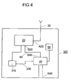
- FIG 4 shows an embodiment of a mobile station 300 is shown with a decoder 310 is equipped.
- the decoder 310 is input side with the transmitting / receiving device 20 and the output side with the control device 40 connected.
- the decoder 310 evaluates the of the transmitting / receiving device 20th received signals from the base station and checks whether in the received signals Control signal is included by the base station, with a predetermined transmission power or a predetermined transmission power level for the transceiver 20 of the Mobile terminal 300 is included.
- the decoder 310 If so, the decoder 310 generates a corresponding control signal S and transmits this via the control line 320 to the controller 40, which in turn the transmitting / receiving device 20 controls such that the of the base station predetermined transmission power or the corresponding transmission signal level is maintained by the transmitting / receiving device 20.
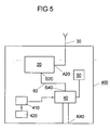
- FIG. 5 shows a mobile radio terminal 400 that is equipped with a voice filter device 410 is equipped.
- the voice filter 410 is input side with a microphone 420 and the output side connected to the control device 40.
- the function of the voice filter device 410 is that of the microphone 420 generated audio signals to filter that only speech signals to the Control device 40 arrive. Other audio signals, such as Ambient noise and the like are received by the voice filter 410 filtered out and suppressed, so that these audio signal components do not belong to the Control device 40 can get.
- the controller 40 is in the mobile station 400 beyond such configured to be the transceiver 20 only then generate electromagnetic transmission power when the voice filtering device 410 Speech signals are "delivered". By contrast, none lie in the control device 40 Speech signals on the part of the voice filter device 410 before, the controller 40 controls the transmitting / receiving device 20 such that no electromagnetic waves over the antenna 30 are radiated.
- FIG. 6 shows a base station 500 which has an antenna 510, one with which Antenna associated transmitting / receiving device 520 and connected to the transmitting / receiving device 520 controller 530 has.
- the base station 500 is also provided with a receive level meter 540 equipped, the input side with the transmitting / receiving device 520 and the output side is connected to the control device 530.
- the reception level meter 540 has the Task, the signals received by the transmitting / receiving device 520 with the Base station 500 related mobile terminals with respect to To evaluate received signal levels; Specifically, the reception level meter 540 measures continuously the signal levels of the received signals and compares the received levels with in a memory 550 stored, predetermined reference values.
- the reception level measuring device 540 determines that, for example, the measured Receiving levels below a predetermined limit, so it controls the Control device 530 such that this the transmitting / receiving device 520 a specifies very high transmission level. Specifically, by the receiving level measuring device 540 achieves that, depending on the transmission / reception conditions of the transmission path between the base station 500 and the connected mobile devices a matching Transmission signal level for the transmitting / receiving device 520 is set. The one of the Transmit / receive device 520 emitted transmission signal level is dependent on this, how high the respective received signal level of the received signals. Aim of this measure is always sending with the lowest possible transmit power to the Radiation exposure through the base station to be kept as low as possible.
- the base station 500 may be configured to operate at time intervals, in where no phone calls are to be transmitted, only once a second Synchronization signals to the mobile stations radiates.
- the base station 500 may be configured to transmit broadcast bursts Synchronizing the mobile stations connected to the base station 500 exclusively in frames 0 and 8 in the DECT standard.
- the mobile radio terminals according to FIGS. 1 to 5 are preferably DECT handsets of cordless DECT phones.
- the base station according to FIG. 6 it is preferably a DECT base station of a cordless DECT phone.
Landscapes
- Engineering & Computer Science (AREA)
- Computer Networks & Wireless Communication (AREA)
- Signal Processing (AREA)
- Mobile Radio Communication Systems (AREA)
- Telephone Function (AREA)
- Processes Of Treating Macromolecular Substances (AREA)
- Transceivers (AREA)
Abstract
Description
- Fig. 1
- ein Ausführungsbeispiel für ein erfindungsgemäßes Mobilfunkendgerät nach der ersten Variante der Erfindung;
- Fig. 2
- ein zweites Ausführungsbeispiel für ein erfindungsgemäßes Mobilfunkendgerät nach der ersten Variante der Erfindung;
- Fig. 3
- ein Ausführungsbeispiel für ein erfindungsgemäßes Mobilfunkendgerät nach der zweiten Variante der Erfindung;
- Fig. 4
- ein weiteres Ausführungsbeispiel für ein erfindungsgemäßes Mobilfunkendgerät nach der zweiten Variante der Erfindung;
- Fig. 5
- ein Ausführungsbeispiel für ein erfindungsgemäßes Mobilfunkendgerät nach der dritten Variante der Erfindung und
- Fig. 6
- ein Ausführungsbeispiel für eine erfindungsgemäße Basisstation gemäß der dritten Variante für eine erfindungsgemäße Basisstation.
- 10
- Mobilfunkendgerät
- 20
- Sende-/Empfangseinrichtung
- 40
- Steuereinrichtung
- 50
- Akku
- 60
- Steuerleitung
- 100
- Mobilfunkendgerät
- 110
- Leitung
- 120
- Schaltelement
- 200
- Mobilfunkendgerät
- 210
- Empfangspegelmesseinrichtung
- 220
- Speicher
- 230
- Steuerleitung
- 300
- Mobilfunkengerät
- 310
- Decodiereinrichtung
- 320
- Steuerleitung
- 400
- Mobilfunkendgerät
- 410
- Sprachfiltereinrichtung
- 420
- Mikrofon
- 500
- Basisstation
- 510
- Antenne
- 520
- Sende-/Empfangseinrichtung
- 530
- Steuereinrichtung
- 540
- Empfangspegelmesseinrichtung
- 550
- Speicher
- K40
- Ladekontakte
- S40
- Steueranschluss
- A40
- Akku-Anschluss
- A20
- Antennenanschluss
Claims (24)
- Mobilfunkendgerät (10, 100, 200, 300, 400) mit einer Sendeeinrichtung (20), die zumindest nach einem vorgegebenen Mobilfunkstandard, insbesondere dem DECT-Standard, arbeitet,
dadurch gekennzeichnet, dass das Mobilfunkendgerät (10, 100, 200, 300, 400) zumindest zwei Betriebsarten aufweist, nämlich eine Normalbetriebsart und mindestens eine weitere Betriebsart, bei der im Vergleich zur Normalbetriebsart zumindest im zeitlichen Mittel weniger elektromagnetische Strahlung erzeugt wird als in der Normalbetriebsart. - Mobilfunkendgerät nach Anspruch 1, dadurch gekennzeichnet, dass das Mobilfunkendgerät (10, 100, 200, 300, 400) derart ausgestaltet ist, dass es selbsttätig oder benutzerseitig von der Normalbetriebsart in die weitere Betriebsart und/oder umgekehrt umschaltbar ist.
- Mobilfunkendgerät nach Anspruch 1 oder 2, dadurch gekennzeichnet, dass das Mobilfunkendgerät (10, 100) derart ausgestaltet ist, dass die Sendeeinrichtung (20) abgeschaltet wird, sobald das Mobilfunkendgerät (10, 100) mit einer Ladeschale einer dem Mobilfunkendgerät (10, 100) zugeordneten Basisstation (500) in Verbindung tritt.
- Mobilfunkendgerät nach Anspruch 3, dadurch gekennzeichnet, dass das Mobilfunkendgerät (100) einen mechanischen Schaltkontakt (120) aufweist, der bei Auflegen des Mobilfunkendgerätes (100) auf der Ladeschale oder beim Einführen des Mobilfunkendgerätes in die Ladeschale die Sendeeinrichtung (20) abschaltet.
- Mobilfunkendgerät nach Anspruch 3, dadurch gekennzeichnet, dass das Mobilfunkendgerät (10) derart ausgestaltet ist, dass es seine Sendeeinrichtung (20) abschaltet, sobalddie Ladekontakte (K40) des Mobilfunkendgerätes (10) mit den Ladekontakten der Basisstation (500) elektrisch kontaktieren und/odermobilfunkendgeräteseitig ein Ladestrom festgestellt wird und/oderein Steuersignal zum Abschalten der mobilfunkendgeräteseitigen Sendeeinrichtung - insbesondere über die Ladekontakte (K40) und/oder über zusätzliche Kontakte - von der Basisstation empfangen wird.
- Mobilfunkendgerät nach einem der vorangehenden Ansprüche 3 bis 5, dadurch gekennzeichnet, dass das Mobilfunkendgerät (10, 100) derart ausgestaltet ist, dass es bei Vorliegen eines von der Basisstation (500) generierten und elektrisch zum Mobilfünkendgerät (10, 100) übertragenen Aufwecksignals den Sendebetrieb wieder aufnimmt.
- Mobilfunkendgerät nach Anspruch 6, dadurch gekennzeichnet, dass das Aufwecksignal über die Ladekontakte (K40) von der Basisstation zum Mobilfunkendgerät (10) übertragen wird.
- Mobilfunkendgerät nach einem der vorangehenden Ansprüche 1 oder 2, dadurch gekennzeichnet, dass das Mobilfunkendgerät (200) derart ausgestaltet ist, dass es mit zumindest zwei Sendeleistungspegeln betrieben werden kann, wobei der jeweilige Sendeleistungspegel von der Übertragungsqualität der Verbindung zwischen der Mobilfunkeinrichtung (200) und der zugeordneten Basisstation bestimmt ist.
- Mobilfunkendgerät nach Anspruch 8, dadurch gekennzeichnet, dass das Mobilfunkendgerät (200) nach einem Empfangen eines Steuersignals der Basisstation den jeweils von der Basisstation mittels des Steuersignals vorgegebenen Sendeleistungspegel einstellt.
- Mobilfunkeinrichtung nach Anspruch 8 oder 9, dadurch gekennzeichnet, dass das Mobilfunkendgerät die jeweilige Empfangsqualität der von der Basisstation gesendeten Signale misst und seinen eigenen Sendeleistungspegel entsprechend derart einstellt, dass bei schlechter Empfangsqualität ein hoher Sendeleistungspegel und bei guter Empfangsqualität ein niedriger Sendeleistungspegel ausgewählt wird.
- Mobilfunkendgerät nach Anspruch 10, dadurch gekennzeichnet, dass das Mobilfunkendgerät als Maß für die Empfangsqualität den Signalpegel des Empfangssignals heranzieht.
- Mobilfunkendgerät nach Anspruch 11, dadurch gekennzeichnet, dass die Höhe des Signalpegels des Empfangssignals unmittelbar als Empfangsqualitätsmesswert bewertet wird.
- Mobilfunkendgerät nach einem der Ansprüche 1 oder 2, dadurch gekennzeichnet, dass das Mobilfunkendgerät (400) in der weiteren Betriebsart während eines Telefonats ausschließlich dann Strahlung erzeugt, wenn Sprachsignale benutzerseitig erzeugt werden.
- Mobilfunkendgerät nach Anspruch 13, dadurch gekennzeichnet, dass das Mobilfunkendgerät eine Sprachfiltereinrichtung (410) aufweist, die Sprachsignale von übrigen akustischen Signalen trennt und ausschließlich die Sprachsignale an die Sendeeinrichtung (20) weiterleitet.
- Basisstation mit einer Sendeeinrichtung, die nach einem vorgegebenen Funkstandard, insbesondere dem DECT-Standard arbeitet, dadurch gekennzeichnet, dass die Basisstation (500) zumindest zwei Betriebsarten aufweist, nämlich eine Normalbetriebsart und mindestens eine weitere Betriebsart, bei der im Vergleich zur Normalbetriebsart zumindest im zeitlichen Mittel weniger Strahlung erzeugt wird als in der Normalbetriebsart.
- Basisstation nach Anspruch 15, dadurch gekennzeichnet, dass die Basisstation (500) derart ausgestaltet ist, dass sie selbsttätig oder benutzerseitig von der Normalbetriebsart in die weitere Betriebsart und/oder umgekehrt umschaltbar ist.
- Basisstation nach einem der vorangehenden Ansprüche 16 oder 17, dadurch gekennzeichnet, dass im Falle eines Sendebetriebs nach dem DECT-Standard die Sendebursts in der weiteren Betriebsart ausschließlich auf die Frames 0 und 8 beschränkt werden.
- Basisstation nach einem der vorangehenden Ansprüche 15 oder 16, dadurch gekennzeichnet, dass in der weiteren Betriebsart die Basisstation ausschließlich einmal in der Sekunde Synchronisationssignale an die angeschlossenen Mobilfunkendgeräte sendet.
- Basisstation nach einem der vorangehenden Ansprüche 15 oder 16, dadurch gekennzeichnet, dass die Basisstation (500) derart ausgestaltet ist, dass sie den Empfangspegel der Empfangssignale misst und die Sendeleistung in Abhängigkeit von dem Signalpegel der empfangenen Signale derart wählt, dass bei schlechter Empfangsqualität ein hoher Sendeleistungspegel und bei guter Empfangsqualität ein niedriger Sendeleistungspegel ausgewählt wird.
- Basisstation nach einem der vorangehenden Ansprüche 15 bis 20, dadurch gekennzeichnet, dass die Basisstation mobilfunkendgeräteindividuell den Empfangspegel der Empfangssignale misst und daraus einen Soll-Sendeleistungspegel für jedes Mobilfunkendgerät bestimmt und ein den Soll-Sendeleistungspegel vorgebendes Steuersignal an das jeweilige Mobilfunkendgerät sendet.
- Basisstation nach einem der vorangehenden Ansprüche 15 bis 20, dadurch gekennzeichnet, dass die Basisstation (500) derart ausgestaltet ist, dass sie ihre Sendeeinrichtung (520) abschaltet, sobald ein Mobilfunkendgerät (10) mit der Ladeschale der Basisstation in Verbindung tritt, sofern lediglich ein einziges Mobilfünkendgerät (10) an der Basisstation angemeldet ist.
- Basisstation nach Anspruch 21, dadurch gekennzeichnet, dass die Basisstation (500) derart ausgestaltet ist, dass sie die Information, dass sich das Mobilfunkendgerät in der Ladeschale der Basisstation befindet, - insbesondere über die Ladekontakte und/oder über zusätzliche Kontakte - von dem Mobilfunkendgerät empfängt.
- Basisstation nach Anspruch 21, dadurch gekennzeichnet, dass die Basisstation (500) derart ausgestaltet ist, dass sie den Ladestrom der Ladeschale selbst überwacht und bei Vorliegen eines Ladestroms ihre Sendeeinrichtung (520) ausschaltet.
- Basisstation nach Anspruch 23, dadurch gekennzeichnet, dass die Basisstation (500) derart ausgestaltet ist, dass sie dem Mobilfunkendgerät ein Steuersignal zum Abschalten der mobilfunkendgeräteseitigen Sendeeinrichtung übermittelt.
Priority Applications (2)
| Application Number | Priority Date | Filing Date | Title |
|---|---|---|---|
| EP10006903A EP2256940A3 (de) | 2003-03-11 | 2004-01-14 | Mobilfunkendgerät |
| EP10006905.3A EP2317661B1 (de) | 2003-03-11 | 2004-01-14 | Basisstation |
Applications Claiming Priority (2)
| Application Number | Priority Date | Filing Date | Title |
|---|---|---|---|
| DE10311675 | 2003-03-11 | ||
| DE10311675 | 2003-03-11 |
Related Child Applications (3)
| Application Number | Title | Priority Date | Filing Date |
|---|---|---|---|
| EP10006905.3A Division EP2317661B1 (de) | 2003-03-11 | 2004-01-14 | Basisstation |
| EP10006903.8 Division-Into | 2010-07-05 | ||
| EP10006905.3 Division-Into | 2010-07-05 |
Publications (3)
| Publication Number | Publication Date |
|---|---|
| EP1458110A2 true EP1458110A2 (de) | 2004-09-15 |
| EP1458110A3 EP1458110A3 (de) | 2005-07-13 |
| EP1458110B1 EP1458110B1 (de) | 2010-08-18 |
Family
ID=32748274
Family Applications (3)
| Application Number | Title | Priority Date | Filing Date |
|---|---|---|---|
| EP10006903A Withdrawn EP2256940A3 (de) | 2003-03-11 | 2004-01-14 | Mobilfunkendgerät |
| EP10006905.3A Expired - Lifetime EP2317661B1 (de) | 2003-03-11 | 2004-01-14 | Basisstation |
| EP04000563A Expired - Lifetime EP1458110B1 (de) | 2003-03-11 | 2004-01-14 | Mobilfunkendgerät |
Family Applications Before (2)
| Application Number | Title | Priority Date | Filing Date |
|---|---|---|---|
| EP10006903A Withdrawn EP2256940A3 (de) | 2003-03-11 | 2004-01-14 | Mobilfunkendgerät |
| EP10006905.3A Expired - Lifetime EP2317661B1 (de) | 2003-03-11 | 2004-01-14 | Basisstation |
Country Status (4)
| Country | Link |
|---|---|
| EP (3) | EP2256940A3 (de) |
| AT (1) | ATE478479T1 (de) |
| DE (1) | DE502004011537D1 (de) |
| ES (1) | ES2350102T3 (de) |
Cited By (4)
| Publication number | Priority date | Publication date | Assignee | Title |
|---|---|---|---|---|
| EP2015550A1 (de) * | 2007-07-11 | 2009-01-14 | Swissvoice SA | Verfahren für ein schnurloses Kommunikationssystem und Kommunikationssystem |
| DE102007049287A1 (de) * | 2007-10-12 | 2009-04-16 | Dernedde, Niels | Verfahren und Vorrichtung zur Verbesserung der Biokompatibilität digitaler, schnurloser Kommunikationseinrichtungen |
| EP1940136A3 (de) * | 2006-12-27 | 2010-04-21 | Brother Kogyo Kabushiki Kaisha | Kabelloses Kommunikationssystem |
| US8098862B2 (en) | 2007-03-20 | 2012-01-17 | Siemens Audiologische Technik Gmbh | Hearing apparatus with a special charging circuit |
Family Cites Families (6)
| Publication number | Priority date | Publication date | Assignee | Title |
|---|---|---|---|---|
| US4731814A (en) * | 1986-02-21 | 1988-03-15 | AT&T Information Systems Inc. American Telephone & Telegraph Company | Computer-controlled cordless telephone |
| DE4426255C2 (de) * | 1994-07-25 | 1998-07-30 | Siemens Ag | Mobile Funksende-/Funkempfangseinrichtung, insbesondere Mobilteil eines Schnurlostelefons |
| DE19617509A1 (de) * | 1996-05-02 | 1997-11-13 | Grundig Ag | Verfahren und Schaltungsanordnung zur automatischen Auslösung von Verbindungen |
| ES2220103T3 (es) * | 1998-06-17 | 2004-12-01 | Siemens Aktiengesellschaft | Procedimiento y sistema para la regulacion de la potencia de transmision de una estacion movil de un sistema de radio movil. |
| US6366572B1 (en) * | 1999-02-04 | 2002-04-02 | Senora Trading Company | Wireless communication system with symmetric communication protocol |
| DE19927585A1 (de) * | 1999-06-16 | 2000-12-28 | Siemens Ag | Basisstation für ein Schnurlostelefon |
-
2004
- 2004-01-14 EP EP10006903A patent/EP2256940A3/de not_active Withdrawn
- 2004-01-14 EP EP10006905.3A patent/EP2317661B1/de not_active Expired - Lifetime
- 2004-01-14 ES ES04000563T patent/ES2350102T3/es not_active Expired - Lifetime
- 2004-01-14 DE DE502004011537T patent/DE502004011537D1/de not_active Expired - Lifetime
- 2004-01-14 AT AT04000563T patent/ATE478479T1/de not_active IP Right Cessation
- 2004-01-14 EP EP04000563A patent/EP1458110B1/de not_active Expired - Lifetime
Cited By (5)
| Publication number | Priority date | Publication date | Assignee | Title |
|---|---|---|---|---|
| EP1940136A3 (de) * | 2006-12-27 | 2010-04-21 | Brother Kogyo Kabushiki Kaisha | Kabelloses Kommunikationssystem |
| US8744498B2 (en) | 2006-12-27 | 2014-06-03 | Brother Kogyo Kabushiki Kaisha | Cordless communication system |
| US8098862B2 (en) | 2007-03-20 | 2012-01-17 | Siemens Audiologische Technik Gmbh | Hearing apparatus with a special charging circuit |
| EP2015550A1 (de) * | 2007-07-11 | 2009-01-14 | Swissvoice SA | Verfahren für ein schnurloses Kommunikationssystem und Kommunikationssystem |
| DE102007049287A1 (de) * | 2007-10-12 | 2009-04-16 | Dernedde, Niels | Verfahren und Vorrichtung zur Verbesserung der Biokompatibilität digitaler, schnurloser Kommunikationseinrichtungen |
Also Published As
| Publication number | Publication date |
|---|---|
| EP2317661A2 (de) | 2011-05-04 |
| ATE478479T1 (de) | 2010-09-15 |
| EP2256940A3 (de) | 2012-03-14 |
| EP2317661A3 (de) | 2012-11-14 |
| EP1458110A3 (de) | 2005-07-13 |
| EP2256940A2 (de) | 2010-12-01 |
| EP1458110B1 (de) | 2010-08-18 |
| ES2350102T3 (es) | 2011-01-18 |
| DE502004011537D1 (de) | 2010-09-30 |
| EP2317661B1 (de) | 2015-12-02 |
Similar Documents
| Publication | Publication Date | Title |
|---|---|---|
| DE3884077T2 (de) | Funktelefonsystem. | |
| DE68928563T2 (de) | Funkfernsprechgerät | |
| DE3882869T2 (de) | Funkanordnung mit zwei Funkgeräten und geteilter Einrichtung. | |
| DE69730529T2 (de) | Schaltkreis und verfahren zur leistungsregelung die bei einem mobiltelefon benutzt wird | |
| DE19857540B4 (de) | Elektronische Schaltung für eine tragbare elektronische Einrichtung | |
| DE60318429T2 (de) | Verfahren und Vorrichtungen zur Initialisierung eines Teilnehmeridentifizierungsmodul | |
| DE202011103558U1 (de) | Detektion von Hochfrequenzabstrahlungen | |
| DE4139041A1 (de) | Fernsteuerungsvorrichtung | |
| DE68924993T2 (de) | Funktelekommunikationsgerät. | |
| DE3885325T2 (de) | Funkfernsprechgerät. | |
| DE69026231T2 (de) | Radiokommunikationsgerät für ein ausgewähltes von mehreren verschiedenen Endgeräten | |
| EP1458110B1 (de) | Mobilfunkendgerät | |
| EP0438770B1 (de) | Energiesparschaltung in einer mobilen Vorrichtung zur drahtlosen Kommunikation | |
| EP2672731B1 (de) | Hörinstrumentsystem mit wiederaufladbarer Batterie | |
| DE69434516T2 (de) | Ladezustandsanzeige für ein Funkgerät | |
| EP1044578B1 (de) | Verfahren zum betrieb eines telekommunikationsendgerätes und telekommunikationsendgerät | |
| DE602004000745T2 (de) | Mobiltelefon und dazugehöriges Energiesparverfahren und Computerprogramm | |
| DE69025226T2 (de) | Funktelefon, geeignet für transportablen und mobilen Betrieb | |
| DE102008038251B4 (de) | Mobiles Endgerät mit einem Antennenmodul und Antenneneinstellverfahren dafür | |
| DE10032233A1 (de) | Verbessertes Mobiltelefon | |
| DE10204851B4 (de) | Datenübertragungssystem mit einstellbarer Sendeleistung | |
| EP0762791A2 (de) | Verfahren zum automatischen Umschalten der Betriebsart in einem Mobiltelefon für Multi-Mode-Betrieb | |
| DE69121596T2 (de) | Radiokommunikationsgerät | |
| DE19600119C2 (de) | Tragbares Teilnehmerendgerät für den Mobilfunk | |
| EP0960483A1 (de) | Funkgerät für mobilfunk mit informationen über den betrieb der mf-verstärkerschaltung |
Legal Events
| Date | Code | Title | Description |
|---|---|---|---|
| PUAI | Public reference made under article 153(3) epc to a published international application that has entered the european phase |
Free format text: ORIGINAL CODE: 0009012 |
|
| AK | Designated contracting states |
Kind code of ref document: A2 Designated state(s): AT BE BG CH CY CZ DE DK EE ES FI FR GB GR HU IE IT LI LU MC NL PT RO SE SI SK TR |
|
| AX | Request for extension of the european patent |
Extension state: AL LT LV MK |
|
| RAP1 | Party data changed (applicant data changed or rights of an application transferred) |
Owner name: DETEWE-DEUTSCHE TELEPHONWERKE AKG & CO. KG |
|
| PUAL | Search report despatched |
Free format text: ORIGINAL CODE: 0009013 |
|
| AK | Designated contracting states |
Kind code of ref document: A3 Designated state(s): AT BE BG CH CY CZ DE DK EE ES FI FR GB GR HU IE IT LI LU MC NL PT RO SE SI SK TR |
|
| AX | Request for extension of the european patent |
Extension state: AL LT LV MK |
|
| RAP1 | Party data changed (applicant data changed or rights of an application transferred) |
Owner name: DETEWE SYSTEMS GMBH |
|
| 17P | Request for examination filed |
Effective date: 20050801 |
|
| AKX | Designation fees paid |
Designated state(s): AT BE BG CH CY CZ DE DK EE ES FI FR GB GR HU IE IT LI LU MC NL PT RO SE SI SK TR |
|
| 17Q | First examination report despatched |
Effective date: 20070109 |
|
| RAP1 | Party data changed (applicant data changed or rights of an application transferred) |
Owner name: AASTRA DETEWE GMBH |
|
| GRAP | Despatch of communication of intention to grant a patent |
Free format text: ORIGINAL CODE: EPIDOSNIGR1 |
|
| GRAS | Grant fee paid |
Free format text: ORIGINAL CODE: EPIDOSNIGR3 |
|
| GRAA | (expected) grant |
Free format text: ORIGINAL CODE: 0009210 |
|
| AK | Designated contracting states |
Kind code of ref document: B1 Designated state(s): AT BE BG CH CY CZ DE DK EE ES FI FR GB GR HU IE IT LI LU MC NL PT RO SE SI SK TR |
|
| REG | Reference to a national code |
Ref country code: GB Ref legal event code: FG4D Free format text: NOT ENGLISH |
|
| REG | Reference to a national code |
Ref country code: CH Ref legal event code: EP |
|
| REG | Reference to a national code |
Ref country code: IE Ref legal event code: FG4D Free format text: LANGUAGE OF EP DOCUMENT: GERMAN |
|
| REF | Corresponds to: |
Ref document number: 502004011537 Country of ref document: DE Date of ref document: 20100930 Kind code of ref document: P |
|
| REG | Reference to a national code |
Ref country code: CH Ref legal event code: NV Representative=s name: PETER RUTZ |
|
| REG | Reference to a national code |
Ref country code: NL Ref legal event code: VDEP Effective date: 20100818 |
|
| RAP2 | Party data changed (patent owner data changed or rights of a patent transferred) |
Owner name: AASTRA DEUTSCHLAND GMBH |
|
| REG | Reference to a national code |
Ref country code: ES Ref legal event code: FG2A Effective date: 20110105 |
|
| PG25 | Lapsed in a contracting state [announced via postgrant information from national office to epo] |
Ref country code: FI Free format text: LAPSE BECAUSE OF FAILURE TO SUBMIT A TRANSLATION OF THE DESCRIPTION OR TO PAY THE FEE WITHIN THE PRESCRIBED TIME-LIMIT Effective date: 20100818 |
|
| PG25 | Lapsed in a contracting state [announced via postgrant information from national office to epo] |
Ref country code: BG Free format text: LAPSE BECAUSE OF FAILURE TO SUBMIT A TRANSLATION OF THE DESCRIPTION OR TO PAY THE FEE WITHIN THE PRESCRIBED TIME-LIMIT Effective date: 20101118 Ref country code: SI Free format text: LAPSE BECAUSE OF FAILURE TO SUBMIT A TRANSLATION OF THE DESCRIPTION OR TO PAY THE FEE WITHIN THE PRESCRIBED TIME-LIMIT Effective date: 20100818 Ref country code: CY Free format text: LAPSE BECAUSE OF FAILURE TO SUBMIT A TRANSLATION OF THE DESCRIPTION OR TO PAY THE FEE WITHIN THE PRESCRIBED TIME-LIMIT Effective date: 20100818 Ref country code: PT Free format text: LAPSE BECAUSE OF FAILURE TO SUBMIT A TRANSLATION OF THE DESCRIPTION OR TO PAY THE FEE WITHIN THE PRESCRIBED TIME-LIMIT Effective date: 20101220 |
|
| REG | Reference to a national code |
Ref country code: IE Ref legal event code: FD4D |
|
| PG25 | Lapsed in a contracting state [announced via postgrant information from national office to epo] |
Ref country code: NL Free format text: LAPSE BECAUSE OF FAILURE TO SUBMIT A TRANSLATION OF THE DESCRIPTION OR TO PAY THE FEE WITHIN THE PRESCRIBED TIME-LIMIT Effective date: 20100818 Ref country code: GR Free format text: LAPSE BECAUSE OF FAILURE TO SUBMIT A TRANSLATION OF THE DESCRIPTION OR TO PAY THE FEE WITHIN THE PRESCRIBED TIME-LIMIT Effective date: 20101119 Ref country code: SE Free format text: LAPSE BECAUSE OF FAILURE TO SUBMIT A TRANSLATION OF THE DESCRIPTION OR TO PAY THE FEE WITHIN THE PRESCRIBED TIME-LIMIT Effective date: 20100818 |
|
| PG25 | Lapsed in a contracting state [announced via postgrant information from national office to epo] |
Ref country code: IE Free format text: LAPSE BECAUSE OF FAILURE TO SUBMIT A TRANSLATION OF THE DESCRIPTION OR TO PAY THE FEE WITHIN THE PRESCRIBED TIME-LIMIT Effective date: 20100818 Ref country code: DK Free format text: LAPSE BECAUSE OF FAILURE TO SUBMIT A TRANSLATION OF THE DESCRIPTION OR TO PAY THE FEE WITHIN THE PRESCRIBED TIME-LIMIT Effective date: 20100818 |
|
| PG25 | Lapsed in a contracting state [announced via postgrant information from national office to epo] |
Ref country code: CZ Free format text: LAPSE BECAUSE OF FAILURE TO SUBMIT A TRANSLATION OF THE DESCRIPTION OR TO PAY THE FEE WITHIN THE PRESCRIBED TIME-LIMIT Effective date: 20100818 Ref country code: EE Free format text: LAPSE BECAUSE OF FAILURE TO SUBMIT A TRANSLATION OF THE DESCRIPTION OR TO PAY THE FEE WITHIN THE PRESCRIBED TIME-LIMIT Effective date: 20100818 Ref country code: RO Free format text: LAPSE BECAUSE OF FAILURE TO SUBMIT A TRANSLATION OF THE DESCRIPTION OR TO PAY THE FEE WITHIN THE PRESCRIBED TIME-LIMIT Effective date: 20100818 Ref country code: SK Free format text: LAPSE BECAUSE OF FAILURE TO SUBMIT A TRANSLATION OF THE DESCRIPTION OR TO PAY THE FEE WITHIN THE PRESCRIBED TIME-LIMIT Effective date: 20100818 |
|
| PLBE | No opposition filed within time limit |
Free format text: ORIGINAL CODE: 0009261 |
|
| STAA | Information on the status of an ep patent application or granted ep patent |
Free format text: STATUS: NO OPPOSITION FILED WITHIN TIME LIMIT |
|
| 26N | No opposition filed |
Effective date: 20110519 |
|
| BERE | Be: lapsed |
Owner name: AASTRA DETEWE G.M.B.H. Effective date: 20110131 |
|
| PG25 | Lapsed in a contracting state [announced via postgrant information from national office to epo] |
Ref country code: MC Free format text: LAPSE BECAUSE OF NON-PAYMENT OF DUE FEES Effective date: 20110131 |
|
| REG | Reference to a national code |
Ref country code: DE Ref legal event code: R097 Ref document number: 502004011537 Country of ref document: DE Effective date: 20110519 |
|
| PG25 | Lapsed in a contracting state [announced via postgrant information from national office to epo] |
Ref country code: BE Free format text: LAPSE BECAUSE OF NON-PAYMENT OF DUE FEES Effective date: 20110131 |
|
| REG | Reference to a national code |
Ref country code: AT Ref legal event code: MM01 Ref document number: 478479 Country of ref document: AT Kind code of ref document: T Effective date: 20110114 |
|
| PG25 | Lapsed in a contracting state [announced via postgrant information from national office to epo] |
Ref country code: AT Free format text: LAPSE BECAUSE OF NON-PAYMENT OF DUE FEES Effective date: 20110114 |
|
| PG25 | Lapsed in a contracting state [announced via postgrant information from national office to epo] |
Ref country code: LU Free format text: LAPSE BECAUSE OF NON-PAYMENT OF DUE FEES Effective date: 20110114 |
|
| PG25 | Lapsed in a contracting state [announced via postgrant information from national office to epo] |
Ref country code: TR Free format text: LAPSE BECAUSE OF FAILURE TO SUBMIT A TRANSLATION OF THE DESCRIPTION OR TO PAY THE FEE WITHIN THE PRESCRIBED TIME-LIMIT Effective date: 20100818 |
|
| PG25 | Lapsed in a contracting state [announced via postgrant information from national office to epo] |
Ref country code: HU Free format text: LAPSE BECAUSE OF FAILURE TO SUBMIT A TRANSLATION OF THE DESCRIPTION OR TO PAY THE FEE WITHIN THE PRESCRIBED TIME-LIMIT Effective date: 20100818 |
|
| REG | Reference to a national code |
Ref country code: FR Ref legal event code: PLFP Year of fee payment: 13 |
|
| REG | Reference to a national code |
Ref country code: FR Ref legal event code: PLFP Year of fee payment: 14 |
|
| PGFP | Annual fee paid to national office [announced via postgrant information from national office to epo] |
Ref country code: ES Payment date: 20161213 Year of fee payment: 14 |
|
| PGFP | Annual fee paid to national office [announced via postgrant information from national office to epo] |
Ref country code: CH Payment date: 20170112 Year of fee payment: 14 |
|
| PGFP | Annual fee paid to national office [announced via postgrant information from national office to epo] |
Ref country code: IT Payment date: 20170123 Year of fee payment: 14 |
|
| REG | Reference to a national code |
Ref country code: FR Ref legal event code: PLFP Year of fee payment: 15 |
|
| REG | Reference to a national code |
Ref country code: DE Ref legal event code: R081 Ref document number: 502004011537 Country of ref document: DE Owner name: MITEL DEUTSCHLAND GMBH, DE Free format text: FORMER OWNER: AASTRA DETEWE GMBH, 10997 BERLIN, DE |
|
| REG | Reference to a national code |
Ref country code: FR Ref legal event code: CD Owner name: MITEL DEUTSCHLAND GMBH, DE Effective date: 20180411 |
|
| REG | Reference to a national code |
Ref country code: CH Ref legal event code: PL |
|
| PG25 | Lapsed in a contracting state [announced via postgrant information from national office to epo] |
Ref country code: LI Free format text: LAPSE BECAUSE OF NON-PAYMENT OF DUE FEES Effective date: 20180131 Ref country code: CH Free format text: LAPSE BECAUSE OF NON-PAYMENT OF DUE FEES Effective date: 20180131 |
|
| PG25 | Lapsed in a contracting state [announced via postgrant information from national office to epo] |
Ref country code: IT Free format text: LAPSE BECAUSE OF NON-PAYMENT OF DUE FEES Effective date: 20180114 |
|
| REG | Reference to a national code |
Ref country code: ES Ref legal event code: FD2A Effective date: 20190730 |
|
| PG25 | Lapsed in a contracting state [announced via postgrant information from national office to epo] |
Ref country code: ES Free format text: LAPSE BECAUSE OF NON-PAYMENT OF DUE FEES Effective date: 20180115 |
|
| PGFP | Annual fee paid to national office [announced via postgrant information from national office to epo] |
Ref country code: GB Payment date: 20221201 Year of fee payment: 20 Ref country code: FR Payment date: 20221208 Year of fee payment: 20 |
|
| PGFP | Annual fee paid to national office [announced via postgrant information from national office to epo] |
Ref country code: DE Payment date: 20221130 Year of fee payment: 20 |
|
| REG | Reference to a national code |
Ref country code: DE Ref legal event code: R071 Ref document number: 502004011537 Country of ref document: DE |
|
| REG | Reference to a national code |
Ref country code: GB Ref legal event code: PE20 Expiry date: 20240113 |
|
| PG25 | Lapsed in a contracting state [announced via postgrant information from national office to epo] |
Ref country code: GB Free format text: LAPSE BECAUSE OF EXPIRATION OF PROTECTION Effective date: 20240113 |