EP1458529B1 - Recouvrement de la fente d'une lame menagee dans un cylindre de coupe et d'alimentation - Google Patents
Recouvrement de la fente d'une lame menagee dans un cylindre de coupe et d'alimentation Download PDFInfo
- Publication number
- EP1458529B1 EP1458529B1 EP01274992A EP01274992A EP1458529B1 EP 1458529 B1 EP1458529 B1 EP 1458529B1 EP 01274992 A EP01274992 A EP 01274992A EP 01274992 A EP01274992 A EP 01274992A EP 1458529 B1 EP1458529 B1 EP 1458529B1
- Authority
- EP
- European Patent Office
- Prior art keywords
- cutting
- transporting roller
- blade
- lateral surface
- roller
- Prior art date
- Legal status (The legal status is an assumption and is not a legal conclusion. Google has not performed a legal analysis and makes no representation as to the accuracy of the status listed.)
- Expired - Lifetime
Links
- 238000005520 cutting process Methods 0.000 title claims description 54
- 239000000463 material Substances 0.000 claims description 10
- 238000000034 method Methods 0.000 claims description 4
- 229910000831 Steel Inorganic materials 0.000 description 4
- 239000010959 steel Substances 0.000 description 4
- 238000010073 coating (rubber) Methods 0.000 description 2
- 230000001419 dependent effect Effects 0.000 description 1
- 230000002093 peripheral effect Effects 0.000 description 1
Images

Classifications
-
- B—PERFORMING OPERATIONS; TRANSPORTING
- B26—HAND CUTTING TOOLS; CUTTING; SEVERING
- B26D—CUTTING; DETAILS COMMON TO MACHINES FOR PERFORATING, PUNCHING, CUTTING-OUT, STAMPING-OUT OR SEVERING
- B26D1/00—Cutting through work characterised by the nature or movement of the cutting member or particular materials not otherwise provided for; Apparatus or machines therefor; Cutting members therefor
- B26D1/01—Cutting through work characterised by the nature or movement of the cutting member or particular materials not otherwise provided for; Apparatus or machines therefor; Cutting members therefor involving a cutting member which does not travel with the work
- B26D1/12—Cutting through work characterised by the nature or movement of the cutting member or particular materials not otherwise provided for; Apparatus or machines therefor; Cutting members therefor involving a cutting member which does not travel with the work having a cutting member moving about an axis
- B26D1/25—Cutting through work characterised by the nature or movement of the cutting member or particular materials not otherwise provided for; Apparatus or machines therefor; Cutting members therefor involving a cutting member which does not travel with the work having a cutting member moving about an axis with a non-circular cutting member
- B26D1/34—Cutting through work characterised by the nature or movement of the cutting member or particular materials not otherwise provided for; Apparatus or machines therefor; Cutting members therefor involving a cutting member which does not travel with the work having a cutting member moving about an axis with a non-circular cutting member moving about an axis parallel to the line of cut
- B26D1/42—Cutting through work characterised by the nature or movement of the cutting member or particular materials not otherwise provided for; Apparatus or machines therefor; Cutting members therefor involving a cutting member which does not travel with the work having a cutting member moving about an axis with a non-circular cutting member moving about an axis parallel to the line of cut and slidably mounted in a rotary member
- B26D1/425—Cutting through work characterised by the nature or movement of the cutting member or particular materials not otherwise provided for; Apparatus or machines therefor; Cutting members therefor involving a cutting member which does not travel with the work having a cutting member moving about an axis with a non-circular cutting member moving about an axis parallel to the line of cut and slidably mounted in a rotary member for thin material, e.g. for sheets, strips or the like
-
- Y—GENERAL TAGGING OF NEW TECHNOLOGICAL DEVELOPMENTS; GENERAL TAGGING OF CROSS-SECTIONAL TECHNOLOGIES SPANNING OVER SEVERAL SECTIONS OF THE IPC; TECHNICAL SUBJECTS COVERED BY FORMER USPC CROSS-REFERENCE ART COLLECTIONS [XRACs] AND DIGESTS
- Y10—TECHNICAL SUBJECTS COVERED BY FORMER USPC
- Y10T—TECHNICAL SUBJECTS COVERED BY FORMER US CLASSIFICATION
- Y10T83/00—Cutting
- Y10T83/465—Cutting motion of tool has component in direction of moving work
- Y10T83/4708—With means to render cutter pass[es] ineffective
-
- Y—GENERAL TAGGING OF NEW TECHNOLOGICAL DEVELOPMENTS; GENERAL TAGGING OF CROSS-SECTIONAL TECHNOLOGIES SPANNING OVER SEVERAL SECTIONS OF THE IPC; TECHNICAL SUBJECTS COVERED BY FORMER USPC CROSS-REFERENCE ART COLLECTIONS [XRACs] AND DIGESTS
- Y10—TECHNICAL SUBJECTS COVERED BY FORMER USPC
- Y10T—TECHNICAL SUBJECTS COVERED BY FORMER US CLASSIFICATION
- Y10T83/00—Cutting
- Y10T83/465—Cutting motion of tool has component in direction of moving work
- Y10T83/4766—Orbital motion of cutting blade
- Y10T83/4795—Rotary tool
-
- Y—GENERAL TAGGING OF NEW TECHNOLOGICAL DEVELOPMENTS; GENERAL TAGGING OF CROSS-SECTIONAL TECHNOLOGIES SPANNING OVER SEVERAL SECTIONS OF THE IPC; TECHNICAL SUBJECTS COVERED BY FORMER USPC CROSS-REFERENCE ART COLLECTIONS [XRACs] AND DIGESTS
- Y10—TECHNICAL SUBJECTS COVERED BY FORMER USPC
- Y10T—TECHNICAL SUBJECTS COVERED BY FORMER US CLASSIFICATION
- Y10T83/00—Cutting
- Y10T83/869—Means to drive or to guide tool
- Y10T83/872—With guard means
-
- Y—GENERAL TAGGING OF NEW TECHNOLOGICAL DEVELOPMENTS; GENERAL TAGGING OF CROSS-SECTIONAL TECHNOLOGIES SPANNING OVER SEVERAL SECTIONS OF THE IPC; TECHNICAL SUBJECTS COVERED BY FORMER USPC CROSS-REFERENCE ART COLLECTIONS [XRACs] AND DIGESTS
- Y10—TECHNICAL SUBJECTS COVERED BY FORMER USPC
- Y10T—TECHNICAL SUBJECTS COVERED BY FORMER US CLASSIFICATION
- Y10T83/00—Cutting
- Y10T83/929—Tool or tool with support
- Y10T83/9309—Anvil
- Y10T83/9312—Rotatable type
Definitions
- the invention relates to a knife slot cover on a cutting and transport roller of a winder according to the preamble of claim 1, and a method according to the preamble of claim 11.
- the cutting blade passes through a generally slot-shaped opening in the lateral surface of the cutting and transport roller and thus cuts through the material webs which rest on the lateral surface of the transport roller.
- said webs of material can be damaged when they come into contact with the slot-shaped opening.
- the invention is therefore based on the object to minimize the resulting damage or to avoid altogether.
- the object is achieved by a device or a method having the features of claim 1 or 11, wherein the slot-shaped opening in the lateral surface of the transport roller is closed when the knife is in its rest position in the interior of the roller.
- closure of the knife forms a part of the circumferential surface of the transport roller in the closed position.
- FIG. 1 shows a section through the region of a web guide roll 1 according to the invention, in which the cutting process takes place.
- the outer jacket In order to allow the knife 4, which is supported and moved by a knife carrier 5, to pass through the outer jacket 2, the outer jacket has a knife passing slot 3.
- the outer jacket 3 consists of a steel jacket 8 and a rubber coating 9.
- the cutting edge 10 of the blade 4 protrudes in the radial direction beyond the peripheral surface 11 of the web guide roller and cuts through the Film web 12.
- the web guide roller has end covers, one of which 13 can be seen in the figure.
- a closure 6 formed as an inflatable tube 6, which is not inflated in Figure 1 and the knife 4 allows passage through the knife slot.
- hoses may be mounted in the blade passage slot 3, which follow one another, for example, in the axial direction (z) of the roller.
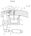
- FIG. 3 once more schematically shows a device according to the invention, in which a slider 15 closes the slot-shaped opening 3 in the shell of the roller.
- the slider 15 has a projection 24 which with little play in the guide groove 17, which is located in the shell of the roller, can slide. In this way, the slider is held and guided.
- the projection 24 is articulated on the pull-push rod 25.
- the pull-push rod is in turn connected to the articulation 20 with the lever 19.
- the lever 19 is attached to the fulcrum 16. Furthermore, the lever is connected via the articulation 21 with the piston 27 of the pneumatic cylinder 28.
- the pneumatic cylinder 28 transmits over its piston 27, the lever 19 and the pull-push rod 25 force on the slider 15 and.open and closes in this way the knife slot.
- a buffer of flexible material 23 such as rubber is provided in the embodiment shown between the slide and the lateral surface. If necessary, such a buffer may contain cavities or recesses 26 so as not to project beyond its bulge in the radial direction over the steel shell of the roll.
- the entire cutting or knife guide mechanism of the cutting and transport roller is not the subject of the present invention and is therefore only outlined here.
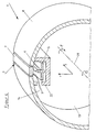
- FIG. 4 is an overall view of a cutting and transporting roller 1 according to the invention, which is shown cut here. Again, the actual cutting mechanism is sketched only in FIG. 3 by the box of the cutting device 22, the knife 4 and the knife carrier 5.
- the knife slot 3 is closed again with a hose 7.
- the hose 7 can be inflated or vented through the flexible supply line 14.
- Devices that provide the required compressed air, or lead into the interior of a roller are also known and are therefore not shown at this point.
- the roller can rotate in both directions about the roller axis 29, which is indicated by the curved arrows ⁇ and - ⁇ , which also indicate the direction of the angular coordinates used for the description.
- the angle coordinates ⁇ clamp together with the also on the basis of a
Landscapes
- Life Sciences & Earth Sciences (AREA)
- Forests & Forestry (AREA)
- Engineering & Computer Science (AREA)
- Mechanical Engineering (AREA)
- Treatment Of Fiber Materials (AREA)
- Advancing Webs (AREA)
- Replacement Of Web Rolls (AREA)
Claims (11)
- Cylindre de coupe et de transport (1) qui présente une face d'enveloppe extérieure (2) pourvue d'une ouverture en forme de fente (3) et qui contient un dispositif de coupe pour des bandes de matériau, qui séparent les bandes de matériau (12) qui s'appliquent à la face d'enveloppe (2) du cylindre de transport (1),• où le dispositif de coupe contient au moins une lame (4) guidée par un porte-lame (5), qui possède elle-même au moins une face de coupe (10),• où le dispositif de coupe, en position de repos se trouve sensiblement à l'intérieur de la face d'enveloppe (2) du cylindre de coupe et de transport (1),• où au moins une lame (4) est montée sur le porte-lame (5) et est déplacée par celui-ci et• où la lame (4) se trouve tout d'abord à l'intérieur de la face d'enveloppe (2) du cylindre de transport et, lors de la coupe de la bande de matériau (12), passe à travers l'ouverture dans la face d'enveloppe (3),caractérisé en ce qu'une fermeture (6) est prévue au moyen de laquelle peut être fermée l'ouverture en forme de fente dans la face d'enveloppe (2) du cylindre de coupe et de transport (1), à travers laquelle passe au moins une lame précitée (4) pendant l'opération de coupe, lorsque la lame, dans sa position de repos, se trouve à l'intérieur du cylindre de transport (1).
- Cylindre de coupe et de transport (1) selon la revendication 1, caractérisé en ce que la fermeture (6) de la fente de passage de lame (3) forme en position de fermeture une partie de la face périphérique du cylindre de coupe et de transport.
- Cylindre de coupe et de transport (1) selon l'une ou plusieurs des revendications précédentes, caractérisé en ce que la fente de passage de lame (3) peut être fermée par au moins un tuyau gonflable (7) qui est fixé au voisinage de la fente de passage de lame (3) au cylindre de coupe et de transport (1).
- Cylindre de coupe et de transport (1) selon l'une ou plusieurs des revendications précédentes, caractérisé en ce que le tuyau (7) est relié par au moins un conduit flexible (14)réalisé comme amenée de pression à une amenée d'air centrale.
- Cylindre de coupe et de transport (1) selon l'une ou plusieurs des revendications précédentes, caractérisé en ce que le tuyau (7) est raccordé à la fois à un conduit d'air comprimé et aussi à un conduit de vide, où des soupapes permettent la libération alternative des deux conduits.
- Cylindre de coupe et de transport (1) selon l'une ou plusieurs des revendications précédentes, caractérisé en ce que la fente de passage de couteau (3) peut être fermée par au moins un volet.
- Cylindre de coupe et de transport (1) selon l'une ou plusieurs des revendications précédentes, caractérisé en ce que le volet, qui ferme la fente de passage de lame (3), est accroché d'une manière tournante à respectivement au moins une tige de piston, où est associé à la tige de piston un vérin qui est accroché à son tour à l'intérieur du cylindre de coupe et de transport et qui peut actionner le volet qui lui est associé en ce que le vérin déplace la tige de piston.
- Cylindre de coupe et de transport (1) selon l'une ou plusieurs des revendications précédentes, caractérisé en ce que la fente de passage de lame peut être fermée par un ou plusieurs tiroirs (15).
- Cylindre de coupe et de transport (1) selon l'une ou plusieurs des revendications précédentes, caractérisé en ce que le tiroir (15) est actionné au moyen d'une unité à piston et à cylindre (27, 28) accroché à l'intérieur du cylindre de guidage de bande (1).
- Cylindre de coupe et de transport (1) selon l'une des revendications précédentes, caractérisé par des dispositifs d'aspiration ou des chambres de vide à l'intérieur de la face d'enveloppe (8) du cylindre de coupe et de transport (1), qui ont des connexions avec des ouvertures dans la face d'enveloppe (8) du cylindre de coupe et de transport.
- Procédé de coupe de bandes de matériau (12), qui s'appliquent à la face d'enveloppe (2) d'un cylindre de coupe et de transport (1), à l'aide d'un dispositif de coupe qui, dans sa position de repos, se trouve sensiblement à l'intérieur de la face d'enveloppe (2) du cylindre de coupe et de transport (1) et qui présente au moins une lame (4) qui se trouve tout d'abord à l'intérieur de la face d'enveloppe (2) du cylindre de coupe et de transport (1), qui est supportée et déplacée par un porte-lame (5) et qui, lors de la coupe de la bande de matériau (12), passe à travers une ouverture (3) dans la face d'enveloppe (2) du cylindre de coupe et de transport (1), caractérisé en ce que l'ouverture dans la face d'enveloppe (2) du cylindre de coupe et de transport (1), à travers laquelle passe au moins une lame (4) pendant l'opération de coupe, est fermée lorsqu'il n'y a pas d'opération de coupe et que la lame (4), dans sa position de repos, se trouve à l'intérieur du cylindre de transport (1).
Priority Applications (1)
| Application Number | Priority Date | Filing Date | Title |
|---|---|---|---|
| AT01274992T ATE340055T1 (de) | 2001-12-19 | 2001-12-19 | Messerschlitzabdeckung an einer schneid- und transportwalze |
Applications Claiming Priority (1)
| Application Number | Priority Date | Filing Date | Title |
|---|---|---|---|
| PCT/EP2001/015090 WO2003051588A1 (fr) | 2001-12-19 | 2001-12-19 | Recouvrement de la fente d'une lame menagee dans un cylindre de coupe et d'alimentation |
Publications (2)
| Publication Number | Publication Date |
|---|---|
| EP1458529A1 EP1458529A1 (fr) | 2004-09-22 |
| EP1458529B1 true EP1458529B1 (fr) | 2006-09-20 |
Family
ID=8164737
Family Applications (1)
| Application Number | Title | Priority Date | Filing Date |
|---|---|---|---|
| EP01274992A Expired - Lifetime EP1458529B1 (fr) | 2001-12-19 | 2001-12-19 | Recouvrement de la fente d'une lame menagee dans un cylindre de coupe et d'alimentation |
Country Status (4)
| Country | Link |
|---|---|
| US (1) | US7320269B2 (fr) |
| EP (1) | EP1458529B1 (fr) |
| DE (1) | DE50111062D1 (fr) |
| WO (1) | WO2003051588A1 (fr) |
Families Citing this family (7)
| Publication number | Priority date | Publication date | Assignee | Title |
|---|---|---|---|---|
| US20080223975A1 (en) * | 2007-03-14 | 2008-09-18 | Miroslav Planeta | Reversible surface winder |
| US20090041553A1 (en) * | 2007-08-06 | 2009-02-12 | 3M Innovative Properties Company | Fly-cutting system and method, and related tooling and articles |
| US9180524B2 (en) | 2007-08-06 | 2015-11-10 | 3M Innovative Properties Company | Fly-cutting head, system and method, and tooling and sheeting produced therewith |
| DE102008049930A1 (de) * | 2008-06-17 | 2009-12-31 | Pama Papiermaschinen Gmbh | Vorrichtung zum Schneiden eines auf einer rotierenden Walze aufgebrachten Wickels |
| DE102010062355A1 (de) | 2010-12-02 | 2012-06-06 | Sms Siemag Ag | Verfahren zum Gießen eines Metallstrangs in einer Stranggießanlage und Stranggießanlage |
| CN203768712U (zh) * | 2013-11-08 | 2014-08-13 | 株式会社瑞光 | 织物切断装置 |
| WO2015160388A1 (fr) * | 2014-04-16 | 2015-10-22 | Westrock Mwv, Llc | Mécanisme de découpage à l'emporte-pièce rotatif de pièce en trois dimensions et son procédé de fonctionnement |
Citations (1)
| Publication number | Priority date | Publication date | Assignee | Title |
|---|---|---|---|---|
| EP0698571A2 (fr) * | 1994-08-17 | 1996-02-28 | Klaus Reinhold | Cylindre de coupe et de transport pour des matériaux en bande |
Family Cites Families (11)
| Publication number | Priority date | Publication date | Assignee | Title |
|---|---|---|---|---|
| US332519A (en) * | 1885-12-15 | Web-perfecting printing-machine | ||
| US3130886A (en) * | 1960-07-15 | 1964-04-28 | Alstermo Bruks Aktiebolag | Former roller with cutting knife |
| US4009626A (en) * | 1975-07-09 | 1977-03-01 | Gressman Richard H | Variable rotary cutter |
| JPS57166267A (en) * | 1981-04-03 | 1982-10-13 | Hitachi Seiko Ltd | Horizontal sewing machine for roulette in folder of rotary press |
| US4998350A (en) * | 1989-12-05 | 1991-03-12 | Thompson Lynn C | Knife and sheath |
| US5464166A (en) * | 1994-08-26 | 1995-11-07 | E. I. Du Pont De Nemours And Company | Method and apparatus for automatic roll transfer |
| US5964975A (en) * | 1997-08-18 | 1999-10-12 | Trine Labeling Systems, Inc. | Method and apparatus of labeling cylindrical articles with label having formed curl |
| US6009781A (en) * | 1998-02-27 | 2000-01-04 | The Procter & Gamble Company | Differential-spacing perforating roll |
| EP1031401B1 (fr) * | 1999-02-25 | 2003-07-02 | FOSBER S.p.A. | Dispositif pour la coupe transversale de matériaux en forme de bandes |
| US6296601B1 (en) * | 1999-07-13 | 2001-10-02 | C.G. Bretting Manufacturing Company, Inc. | Vacuum assisted roll apparatus and method |
| DE10047545B4 (de) * | 2000-09-22 | 2007-12-27 | Windmöller & Hölscher Kg | Schneid- und Transportwalze mit integrierter Schneidvorrichtung mit schwenkbaren Schneidflächen und Verfahren zum Schneiden von Materialbahnen mithilfe einer solchen Walze |
-
2001
- 2001-12-19 US US10/491,341 patent/US7320269B2/en not_active Expired - Fee Related
- 2001-12-19 DE DE50111062T patent/DE50111062D1/de not_active Expired - Lifetime
- 2001-12-19 WO PCT/EP2001/015090 patent/WO2003051588A1/fr not_active Ceased
- 2001-12-19 EP EP01274992A patent/EP1458529B1/fr not_active Expired - Lifetime
Patent Citations (1)
| Publication number | Priority date | Publication date | Assignee | Title |
|---|---|---|---|---|
| EP0698571A2 (fr) * | 1994-08-17 | 1996-02-28 | Klaus Reinhold | Cylindre de coupe et de transport pour des matériaux en bande |
Also Published As
| Publication number | Publication date |
|---|---|
| US7320269B2 (en) | 2008-01-22 |
| WO2003051588A1 (fr) | 2003-06-26 |
| US20040194596A1 (en) | 2004-10-07 |
| DE50111062D1 (de) | 2006-11-02 |
| EP1458529A1 (fr) | 2004-09-22 |
Similar Documents
| Publication | Publication Date | Title |
|---|---|---|
| EP0698571B1 (fr) | Cylindre de coupe et de transport pour des matériaux en bande | |
| DE2721883A1 (de) | Verfahren zur uebertragung einer papierbahn in einer papiermaschine sowie vorrichtung zur ausfuehrung des verfahrens | |
| DE2909006C2 (fr) | ||
| DE2904378A1 (de) | Greifvorrichtung des zangentyps mit zwei schwenkbaren greifarmen zum auffangen und abtransport von fertigen werkstuecken von drehbaenken oder anderen werkzeugmaschinen | |
| DE69302033T2 (de) | Rollenstopper und Verfahren zu dessen Betrieb | |
| EP1360135B1 (fr) | Cylindre a lames de pliage d'une machine de pliage et procede de reglage d'une lame de pliage | |
| EP1458529A1 (fr) | Recouvrement de la fente d'une lame menagee dans un cylindre de coupe et d'alimentation | |
| DE10112416C1 (de) | Wendestange | |
| DE2807895C2 (de) | Aus einer Druckmittelquelle betriebene schlauchlose Arbeitsstückklemme für Nähautomaten | |
| DE10051372A1 (de) | Messerschlitzabdeckung an einer Schneid- und Transportwalze | |
| EP1882662B2 (fr) | Système de ralentisseur de feuilles destiné au freinage de feuilles d'impression | |
| DE19932070A1 (de) | Exemplarführungseinrichtung mit variabler Geometrie | |
| AT516266B1 (de) | Verfahren und Vorrichtung zum Überführen eines Vorlaufstreifens von einer ersten Verarbeitungseinrichtung zu einer zweiten Verarbeitungseinrichtung | |
| EP1088780A2 (fr) | Dispositif pour fermer sélectivement des orifice de soufflage dans dispositifs de guidage ou barres pour le support à imprimer dans machines d'impression rotatives | |
| DE1920445B2 (de) | Vorrichtung zum aufwickeln laufender werkstoffbahnen | |
| EP3162747B1 (fr) | Dispositif receveur de feuilles comprenant un souffleur | |
| DE3220798C1 (de) | Auslegevorrichtung an Bogenrotationsdruckmaschinen | |
| DE19954554A1 (de) | Ausleger einer Bogen verarbeitenden Maschine | |
| EP4370294A1 (fr) | Rouleau de contact pour un dispositif d'enroulement | |
| CH690673A5 (de) | Verfahren und Vorrichtung zum Spalten von Holz. | |
| DE3914547A1 (de) | Vorrichtung zum auf- oder umrollen einer papierbahn | |
| EP1654097B1 (fr) | Cylindre de decoupe et de transport utilise dans un dispositif d'enroulement servant a enrouler des bandes de materiau | |
| DE102019203346A1 (de) | Bahnausrichtvorrichtung und Ausrichtverfahren für eine flexible Materialbahn | |
| EP1232983B1 (fr) | Dispositif pour guider des cahiers plats dans des machines à plier | |
| DE1238304B (fr) |
Legal Events
| Date | Code | Title | Description |
|---|---|---|---|
| PUAI | Public reference made under article 153(3) epc to a published international application that has entered the european phase |
Free format text: ORIGINAL CODE: 0009012 |
|
| 17P | Request for examination filed |
Effective date: 20040719 |
|
| AK | Designated contracting states |
Kind code of ref document: A1 Designated state(s): AT DE IT |
|
| GRAP | Despatch of communication of intention to grant a patent |
Free format text: ORIGINAL CODE: EPIDOSNIGR1 |
|
| GRAS | Grant fee paid |
Free format text: ORIGINAL CODE: EPIDOSNIGR3 |
|
| GRAA | (expected) grant |
Free format text: ORIGINAL CODE: 0009210 |
|
| AK | Designated contracting states |
Kind code of ref document: B1 Designated state(s): AT DE IT |
|
| REF | Corresponds to: |
Ref document number: 50111062 Country of ref document: DE Date of ref document: 20061102 Kind code of ref document: P |
|
| PLBE | No opposition filed within time limit |
Free format text: ORIGINAL CODE: 0009261 |
|
| STAA | Information on the status of an ep patent application or granted ep patent |
Free format text: STATUS: NO OPPOSITION FILED WITHIN TIME LIMIT |
|
| 26N | No opposition filed |
Effective date: 20070621 |
|
| PGFP | Annual fee paid to national office [announced via postgrant information from national office to epo] |
Ref country code: AT Payment date: 20081216 Year of fee payment: 8 |
|
| PG25 | Lapsed in a contracting state [announced via postgrant information from national office to epo] |
Ref country code: AT Free format text: LAPSE BECAUSE OF NON-PAYMENT OF DUE FEES Effective date: 20091219 |
|
| PGFP | Annual fee paid to national office [announced via postgrant information from national office to epo] |
Ref country code: IT Payment date: 20121218 Year of fee payment: 12 |
|
| PGFP | Annual fee paid to national office [announced via postgrant information from national office to epo] |
Ref country code: DE Payment date: 20121231 Year of fee payment: 12 |
|
| REG | Reference to a national code |
Ref country code: DE Ref legal event code: R119 Ref document number: 50111062 Country of ref document: DE |
|
| REG | Reference to a national code |
Ref country code: DE Ref legal event code: R119 Ref document number: 50111062 Country of ref document: DE Effective date: 20140701 |
|
| PG25 | Lapsed in a contracting state [announced via postgrant information from national office to epo] |
Ref country code: DE Free format text: LAPSE BECAUSE OF NON-PAYMENT OF DUE FEES Effective date: 20140701 |
|
| PG25 | Lapsed in a contracting state [announced via postgrant information from national office to epo] |
Ref country code: IT Free format text: LAPSE BECAUSE OF NON-PAYMENT OF DUE FEES Effective date: 20131231 |
|
| PG25 | Lapsed in a contracting state [announced via postgrant information from national office to epo] |
Ref country code: IT Free format text: LAPSE BECAUSE OF NON-PAYMENT OF DUE FEES Effective date: 20131219 |