EP1458902B1 - Verfahren und vorrichtung zur verdichtung poröser substrate mittels chemischer dampfinfiltration - Google Patents
Verfahren und vorrichtung zur verdichtung poröser substrate mittels chemischer dampfinfiltration Download PDFInfo
- Publication number
- EP1458902B1 EP1458902B1 EP02799114A EP02799114A EP1458902B1 EP 1458902 B1 EP1458902 B1 EP 1458902B1 EP 02799114 A EP02799114 A EP 02799114A EP 02799114 A EP02799114 A EP 02799114A EP 1458902 B1 EP1458902 B1 EP 1458902B1
- Authority
- EP
- European Patent Office
- Prior art keywords
- oven
- reactive gas
- gas
- substrates
- temperature
- Prior art date
- Legal status (The legal status is an assumption and is not a legal conclusion. Google has not performed a legal analysis and makes no representation as to the accuracy of the status listed.)
- Expired - Lifetime
Links
- 239000000758 substrate Substances 0.000 title claims abstract description 57
- 238000000034 method Methods 0.000 title claims abstract description 29
- 238000009434 installation Methods 0.000 title claims description 28
- 238000001764 infiltration Methods 0.000 title claims description 8
- 230000008595 infiltration Effects 0.000 title claims description 8
- 239000000126 substance Substances 0.000 title claims description 7
- 238000011068 loading method Methods 0.000 claims abstract description 36
- 238000000280 densification Methods 0.000 claims abstract description 19
- 239000011159 matrix material Substances 0.000 claims abstract description 15
- 239000002243 precursor Substances 0.000 claims abstract description 11
- 238000011144 upstream manufacturing Methods 0.000 claims abstract description 4
- 239000007789 gas Substances 0.000 claims description 136
- 238000010438 heat treatment Methods 0.000 claims description 49
- 239000002131 composite material Substances 0.000 claims description 12
- OKTJSMMVPCPJKN-UHFFFAOYSA-N Carbon Chemical compound [C] OKTJSMMVPCPJKN-UHFFFAOYSA-N 0.000 claims description 10
- 229910052799 carbon Inorganic materials 0.000 claims description 6
- 238000004891 communication Methods 0.000 claims description 3
- 239000002737 fuel gas Substances 0.000 claims description 3
- 238000001564 chemical vapour infiltration Methods 0.000 claims 1
- 239000011148 porous material Substances 0.000 claims 1
- VNWKTOKETHGBQD-UHFFFAOYSA-N methane Chemical compound C VNWKTOKETHGBQD-UHFFFAOYSA-N 0.000 description 7
- 239000000919 ceramic Substances 0.000 description 6
- 239000000376 reactant Substances 0.000 description 6
- 235000021183 entrée Nutrition 0.000 description 5
- 238000004519 manufacturing process Methods 0.000 description 5
- 239000000463 material Substances 0.000 description 5
- 239000011153 ceramic matrix composite Substances 0.000 description 4
- 229910002804 graphite Inorganic materials 0.000 description 4
- 239000010439 graphite Substances 0.000 description 4
- 229920000049 Carbon (fiber) Polymers 0.000 description 3
- 239000004917 carbon fiber Substances 0.000 description 3
- 239000000470 constituent Substances 0.000 description 3
- 239000012530 fluid Substances 0.000 description 3
- ATUOYWHBWRKTHZ-UHFFFAOYSA-N Propane Chemical compound CCC ATUOYWHBWRKTHZ-UHFFFAOYSA-N 0.000 description 2
- 230000015572 biosynthetic process Effects 0.000 description 2
- 239000003153 chemical reaction reagent Substances 0.000 description 2
- 229930195733 hydrocarbon Natural products 0.000 description 2
- 150000002430 hydrocarbons Chemical class 0.000 description 2
- 238000002955 isolation Methods 0.000 description 2
- 239000005055 methyl trichlorosilane Substances 0.000 description 2
- JLUFWMXJHAVVNN-UHFFFAOYSA-N methyltrichlorosilane Chemical compound C[Si](Cl)(Cl)Cl JLUFWMXJHAVVNN-UHFFFAOYSA-N 0.000 description 2
- 239000000203 mixture Substances 0.000 description 2
- 230000003071 parasitic effect Effects 0.000 description 2
- 239000002296 pyrolytic carbon Substances 0.000 description 2
- 230000001105 regulatory effect Effects 0.000 description 2
- 230000002787 reinforcement Effects 0.000 description 2
- 125000006850 spacer group Chemical group 0.000 description 2
- 239000004215 Carbon black (E152) Substances 0.000 description 1
- 229920002134 Carboxymethyl cellulose Polymers 0.000 description 1
- UFHFLCQGNIYNRP-UHFFFAOYSA-N Hydrogen Chemical compound [H][H] UFHFLCQGNIYNRP-UHFFFAOYSA-N 0.000 description 1
- 229910000831 Steel Inorganic materials 0.000 description 1
- 239000007833 carbon precursor Substances 0.000 description 1
- 235000010948 carboxy methyl cellulose Nutrition 0.000 description 1
- 229920006184 cellulose methylcellulose Polymers 0.000 description 1
- 238000006243 chemical reaction Methods 0.000 description 1
- 238000012710 chemistry, manufacturing and control Methods 0.000 description 1
- 239000000567 combustion gas Substances 0.000 description 1
- 230000001276 controlling effect Effects 0.000 description 1
- 238000000354 decomposition reaction Methods 0.000 description 1
- 238000009792 diffusion process Methods 0.000 description 1
- 238000010790 dilution Methods 0.000 description 1
- 239000012895 dilution Substances 0.000 description 1
- 230000000694 effects Effects 0.000 description 1
- 229940082150 encore Drugs 0.000 description 1
- 238000002474 experimental method Methods 0.000 description 1
- 230000002349 favourable effect Effects 0.000 description 1
- 239000000835 fiber Substances 0.000 description 1
- 238000009413 insulation Methods 0.000 description 1
- 239000012212 insulator Substances 0.000 description 1
- -1 natural gas Chemical class 0.000 description 1
- 239000003345 natural gas Substances 0.000 description 1
- 235000020004 porter Nutrition 0.000 description 1
- 239000001294 propane Substances 0.000 description 1
- 239000011819 refractory material Substances 0.000 description 1
- 238000007789 sealing Methods 0.000 description 1
- HBMJWWWQQXIZIP-UHFFFAOYSA-N silicon carbide Chemical compound [Si+]#[C-] HBMJWWWQQXIZIP-UHFFFAOYSA-N 0.000 description 1
- 229910010271 silicon carbide Inorganic materials 0.000 description 1
- 239000004071 soot Substances 0.000 description 1
- 239000010959 steel Substances 0.000 description 1
- 230000009466 transformation Effects 0.000 description 1
- 230000001131 transforming effect Effects 0.000 description 1
Images




Classifications
-
- C—CHEMISTRY; METALLURGY
- C04—CEMENTS; CONCRETE; ARTIFICIAL STONE; CERAMICS; REFRACTORIES
- C04B—LIME, MAGNESIA; SLAG; CEMENTS; COMPOSITIONS THEREOF, e.g. MORTARS, CONCRETE OR LIKE BUILDING MATERIALS; ARTIFICIAL STONE; CERAMICS; REFRACTORIES; TREATMENT OF NATURAL STONE
- C04B41/00—After-treatment of mortars, concrete, artificial stone or ceramics; Treatment of natural stone
- C04B41/45—Coating or impregnating, e.g. injection in masonry, partial coating of green or fired ceramics, organic coating compositions for adhering together two concrete elements
-
- C—CHEMISTRY; METALLURGY
- C23—COATING METALLIC MATERIAL; COATING MATERIAL WITH METALLIC MATERIAL; CHEMICAL SURFACE TREATMENT; DIFFUSION TREATMENT OF METALLIC MATERIAL; COATING BY VACUUM EVAPORATION, BY SPUTTERING, BY ION IMPLANTATION OR BY CHEMICAL VAPOUR DEPOSITION, IN GENERAL; INHIBITING CORROSION OF METALLIC MATERIAL OR INCRUSTATION IN GENERAL
- C23C—COATING METALLIC MATERIAL; COATING MATERIAL WITH METALLIC MATERIAL; SURFACE TREATMENT OF METALLIC MATERIAL BY DIFFUSION INTO THE SURFACE, BY CHEMICAL CONVERSION OR SUBSTITUTION; COATING BY VACUUM EVAPORATION, BY SPUTTERING, BY ION IMPLANTATION OR BY CHEMICAL VAPOUR DEPOSITION, IN GENERAL
- C23C16/00—Chemical coating by decomposition of gaseous compounds, without leaving reaction products of surface material in the coating, i.e. chemical vapour deposition [CVD] processes
- C23C16/04—Coating on selected surface areas, e.g. using masks
- C23C16/045—Coating cavities or hollow spaces, e.g. interior of tubes; Infiltration of porous substrates
-
- C—CHEMISTRY; METALLURGY
- C04—CEMENTS; CONCRETE; ARTIFICIAL STONE; CERAMICS; REFRACTORIES
- C04B—LIME, MAGNESIA; SLAG; CEMENTS; COMPOSITIONS THEREOF, e.g. MORTARS, CONCRETE OR LIKE BUILDING MATERIALS; ARTIFICIAL STONE; CERAMICS; REFRACTORIES; TREATMENT OF NATURAL STONE
- C04B35/00—Shaped ceramic products characterised by their composition; Ceramics compositions; Processing powders of inorganic compounds preparatory to the manufacturing of ceramic products
- C04B35/71—Ceramic products containing macroscopic reinforcing agents
- C04B35/78—Ceramic products containing macroscopic reinforcing agents containing non-metallic materials
- C04B35/80—Fibres, filaments, whiskers, platelets, or the like
- C04B35/83—Carbon fibres in a carbon matrix
-
- C—CHEMISTRY; METALLURGY
- C23—COATING METALLIC MATERIAL; COATING MATERIAL WITH METALLIC MATERIAL; CHEMICAL SURFACE TREATMENT; DIFFUSION TREATMENT OF METALLIC MATERIAL; COATING BY VACUUM EVAPORATION, BY SPUTTERING, BY ION IMPLANTATION OR BY CHEMICAL VAPOUR DEPOSITION, IN GENERAL; INHIBITING CORROSION OF METALLIC MATERIAL OR INCRUSTATION IN GENERAL
- C23C—COATING METALLIC MATERIAL; COATING MATERIAL WITH METALLIC MATERIAL; SURFACE TREATMENT OF METALLIC MATERIAL BY DIFFUSION INTO THE SURFACE, BY CHEMICAL CONVERSION OR SUBSTITUTION; COATING BY VACUUM EVAPORATION, BY SPUTTERING, BY ION IMPLANTATION OR BY CHEMICAL VAPOUR DEPOSITION, IN GENERAL
- C23C16/00—Chemical coating by decomposition of gaseous compounds, without leaving reaction products of surface material in the coating, i.e. chemical vapour deposition [CVD] processes
- C23C16/44—Chemical coating by decomposition of gaseous compounds, without leaving reaction products of surface material in the coating, i.e. chemical vapour deposition [CVD] processes characterised by the method of coating
- C23C16/455—Chemical coating by decomposition of gaseous compounds, without leaving reaction products of surface material in the coating, i.e. chemical vapour deposition [CVD] processes characterised by the method of coating characterised by the method used for introducing gases into reaction chamber or for modifying gas flows in reaction chamber
- C23C16/45563—Gas nozzles
- C23C16/4557—Heated nozzles
-
- Y—GENERAL TAGGING OF NEW TECHNOLOGICAL DEVELOPMENTS; GENERAL TAGGING OF CROSS-SECTIONAL TECHNOLOGIES SPANNING OVER SEVERAL SECTIONS OF THE IPC; TECHNICAL SUBJECTS COVERED BY FORMER USPC CROSS-REFERENCE ART COLLECTIONS [XRACs] AND DIGESTS
- Y10—TECHNICAL SUBJECTS COVERED BY FORMER USPC
- Y10S—TECHNICAL SUBJECTS COVERED BY FORMER USPC CROSS-REFERENCE ART COLLECTIONS [XRACs] AND DIGESTS
- Y10S427/00—Coating processes
- Y10S427/10—Chemical vapor infiltration, i.e. CVI
Definitions
- the invention relates to the densification of porous substrates by chemical vapor infiltration.
- thermostructural composite material parts that is to say of composite material having both mechanical properties that make it suitable for constituting structural parts and the capacity to keep these properties up to high temperatures.
- thermostructural composite materials are carbon / carbon (C / C) composites having a carbon fiber reinforcement texture densified by a pyrolytic carbon matrix and ceramic matrix composites (CMC) having a fiber reinforcement texture refractories (carbon or ceramic) densified by a ceramic matrix.
- a well known process for densifying porous substrates for making C / C composite or CMC parts is chemical vapor infiltration.
- the substrates to be densified are placed in a charging zone of an oven where they are heated.
- a reactive gas containing one or more gaseous precursors of the material constituting the matrix is introduced into the furnace.
- the temperature and the pressure in the furnace are adjusted to allow the reactive gas to diffuse within the porosity of the substrates and to form a deposit of the material constituting the matrix by decomposition of one or more constituents of the reactive gas or reaction between several constituents, these constituents forming the precursor of the matrix.
- the process is carried out under reduced pressure in order to promote the diffusion of the reactive gases into the substrates.
- the transformation temperature of the precursor (s) to form the material of the matrix such as pyrolytic or ceramic carbon, is in most cases greater than 900 ° C., typically close to 1000 ° C.
- the furnaces usually comprise a reactive gas heating zone located between the inlet of the reactive gas in the furnace and the loading zone.
- the heating zone comprises a plurality of perforated trays traversed by the reactive gas.
- the gas heating trays, as well as the substrates are heated because of their presence in the oven.
- the heating of the latter is generally provided by means of an armature (or susceptor), for example graphite, which defines the side wall of the furnace and is coupled to an inductor surrounding the furnace.
- a significant example is the densification of substrates consisting of carbon fiber annular preforms, or predensified annular blanks, for the production of C / C composite brake disks.
- the substrates are arranged in one or more vertical stacks in the loading zone, above the heating zone of the reactive gas located at the bottom of the furnace.
- a temperature gradient is observed between the bottom of the loading zone and the rest of the latter, the temperature at the bottom of the stack may be several tens of ° C lower to that prevailing at the level of the rest of the pile. This results in a significant densification gradient between the substrates according to their position in the stack.
- furnaces have a high productivity, be they furnaces in service or new furnaces to be realized, thus a ratio as high as possible between volume useful dedicated to the loading of the substrates and volume dedicated to the heating of the reactive gas.
- the object of the invention is to propose a process for densification by chemical vapor infiltration which makes it possible to have a very reduced temperature gradient throughout the loading zone without requiring a large volume of the heating zone of the reactive gas, therefore without affecting, and even improving, the productivity of the ovens.
- Preheating the reagent gas outside the furnace allows the heating zone in the furnace to be more efficient in bringing the reactant gas to the desired temperature as soon as it enters the substrate loading zone.
- the reactive gas is preheated before entering the oven to be brought, at its entry into the oven, at a temperature preferably at least equal to 200 ° C. vs.
- the preheating temperature of the gas does not exceed 800 ° C, or even 600 ° C to avoid a risk of parasitic deposits by transforming the precursor (s) before entering the furnace, and to allow the use of relatively common materials for preheated reactive gas furnace feed pipes and components such as valve (s) and seal (s) mounted thereon pipes.
- the preheating can be performed at a gas pressure substantially equal to that prevailing in the oven or at a higher pressure. In the latter case, the preheated reactive gas is expanded before entering the oven.
- the invention also aims to provide an installation for implementing the method.
- an installation of the type comprising: an oven, a substrate loading zone in the oven, means for heating substrates in the loading zone, at least one reactive gas inlet in the oven, and a a gas heating zone located in the furnace between the reactant gas inlet and the loading zone, installation in which, in accordance with the invention, there is further provided at least one gas preheating device located outside the oven and connected to at least one reactive gas inlet in the oven, so as to preheat the gas reagent before entering the oven.
- the preheating device comprises a current passage tube inserted on a conduit for supplying the reactive gas to the inlet of the reactive gas in the oven.
- the preheating device comprises a gas boiler or an electric oven traversed by at least one pipe or a bundle of tubes for the circulation of the reactive gas to be preheated.
- Embodiments of the method and the installation according to the invention will be described below in the context of the application to the densification of annular porous substrates consisting of carbon fiber preforms or predensed blanks intended for the production of brake discs made of C / C composite material. Such discs are commonly used for aircraft wheels and for racing automobiles.
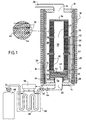
- FIG. 1 schematically shows an oven 10 delimited by a cylindrical lateral wall 12, a bottom wall 14 and an upper wall 16.
- the wall 12 constitutes an armature, or susceptor, for example made of graphite, which is coupled with an inductor 18 located outside the oven, with the interposition of an insulator 20.
- the heating of the furnace is provided by the armature 12 by electrical supply of the inductor 18.
- the reactive gas is introduced into the furnace through a passage 22 formed in the bottom wall 14 and the effluent gas is extracted through a passage 24 formed in the upper wall 16, the passage 24 being connected by a pipe 26 to means suction, such as a vacuum pump (not shown).
- the substrates to be densified 32 are arranged to form an annular vertical stack closed at its top by a cover 34.
- the stacked substrates share the internal volume of the loading zone 30 between a volume 36 internal to the stack formed by the aligned central passages of the substrates, and a volume 38 external to the stack.
- the stack of substrates rests on a lower support plate 40 and can be divided into several superimposed sections separated by one or more intermediate plates 42, the plates 40, 42 having central passages 41, 43 aligned with those of the substrates 32.
- a single battery is shown in Figure 1, several batteries may be arranged side by side in the furnace 10 as described below.
- each substrate 32 is separated from an adjacent substrate or, if appropriate, a tray 40, 42 or cover 34 by spacers 44 which define gaps 46.
- the shims 44 are arranged to provide passages for the gas between the volumes 36 and 38 through intervals 46. These passages can be made to substantially equalize the pressure between the volumes. 36 and 38, as described in US Pat. No. 5,904,957, or so as to constitute simple leakage passages maintaining a pressure gradient between volumes 36 and 38, as described in the patent application filed under number FR 01 03004 .
- a gas heating zone 50 extends between the bottom 14 of the oven and the lower support plate 40.
- the heating zone 50 comprises several perforated trays 52, for example made of graphite, arranged above one another. others, and spaced from each other.
- the trays 52 can be housed in a housing having a bottom 54 and a side wall 56, and delimiting the zone of heater.
- a line 58 connects the reactive gas inlet 22 to the heating zone 30 through the bottom 54.
- Legs and posts 28 support the heating housing and trays 40, 42. All of these elements is made for example of graphite.
- the reactive gas admitted into the furnace through the inlet 22 passes through the heating zone 50 and reaches the volume 36 through the central orifice 41 of the plate 40.
- the reactive gas circulates from the volume 36 to the volume 38, passing through through the porosity of the substrates 32 and through the passages in the gaps 46.
- the effluent gas is extracted from the volume 38 through the outlet 24.
- the volume 36 can be closed at its lower part and placed in communication with the outlet 24 at its upper part.
- the reactive gas from the heating zone 30 is then admitted into the volume 38 of the loading zone and the circulation of the gas in this zone is from the volume 38 to the volume 36, the volume 38 being closed at its upper part.
- the inlet of the reactive gas can be made through the upper wall 16 of the oven, the heating zone then being located at the upper part of the oven. That of the two volumes 36, 38 which is in communication with the heating zone is closed at its lower part while the other of these two volumes communicates with a gas outlet formed in the lower wall of the furnace.
- the reactive gas contains one or more carbon precursors such as hydrocarbons. Commonly used precursors are methane, propane or a mixture of both.
- the chemical vapor infiltration is carried out at a temperature generally greater than 900 ° C., for example between 950 ° C. and 1100 ° C., and under a reduced pressure, for example less than 0.1 kPa.
- the reactive gas is preheated before being admitted into the oven, by passing through a preheating device 60 connected by a supply line 62 to the inlet 22 of the oven.
- the pipe 62 is preferably thermally insulated.
- An isolation valve 64 is mounted on line 62 immediately upstream of the inlet 22 of the furnace so as to be able to isolate the furnace from the reactive gas supply circuit.
- the preheating device comprises a flow-through tube 66 which is traversed by the reactive gas coming from a source 68 and is connected to the pipe 62.
- the electric current is produced by a power supply circuit 70 delivering a voltage U and connected to the ends of the tube portion.
- the circuit 70 receives information provided by a sensor 72, for example a thermocouple, disposed at the outlet of the preheating device.
- the preheating temperature is regulated to a predetermined value by automatic adjustment of the voltage U as a function of the temperature measured by the sensor 72.
- the heating of the reactive gas can be carried out under the reduced pressure prevailing in the furnace, an expander 74 being disposed at the outlet of the gas source 68.
- the heating of the reactive gas can be carried out under a pressure greater than that prevailing in the furnace, namely a pressure intermediate that of the source 68 and that prevailing in the furnace.
- the preheated reactive gas is expanded before entering the oven, for example by passing through a calibrated orifice mounted in the feed pipe 62.
- the purpose of the preheating of the reactive gas is to allow the gas, after additional heating by passing through the heating zone 50, to enter the charging zone at a temperature equal to or close to that necessary to avoid a significant temperature gradient between the bottom of the loading area and the rest of it.
- the preheating of the reactive gas should preferably be carried out to bring the gas into the oven at a temperature of at least 200 ° C.
- the preheating temperature that is to say the temperature at the outlet of the preheating device, must however be limited to avoid the risk of formation of parasitic deposits (soot) in the feed pipe 62, and due to constraints Technological order.
- a preheating temperature of at most 800 ° C. will be chosen to avoid extraneous deposits, and preferably at most equal to 600 ° C. in order to be able to use materials that are affordable for line 62 (for example a steel ) as well as for the isolation valve 64 and other possible components exposed to the preheated gas, such as seals.
- the temperature of the preheated gas can lose a few degrees to a few tens of degrees before going back to its entry into the oven, or even a little before its entry, because of the influence of the oven atmosphere.
- Curve D in FIG. 2 illustrates the temperature variation of the measured reactive gas until it enters the charging zone of the oven.
- the preheating of the gas at 600 ° C. and 500 ° C. makes it possible to bring it to a temperature of approximately 993 ° C. and 975 ° C at its entry into the loading zone while, without preheating (curve D), this temperature is significantly lower than 850 ° C.
- the preheating at 500 ° C retains its efficiency with a substantially increased flow rate since the temperature at the inlet of the loading zone is about 950 ° C (curve C). Preheating therefore allows an increase in the flow rate of the reactive gas, which is favorable to a decrease in the total duration of the densification process.
- FIG. 3 shows an alternative embodiment of the densification installation which differs from that of FIG. 1 in that the preheating device 80 is formed not by a tube with current flow, but by a gas boiler.
- the boiler 80 comprises a burner 82 supplied with fuel gas, for example gaseous hydrocarbon such as natural gas, via a line 75 on which a control valve 76 is mounted.
- the burner 82 is supplied with dilution air via a line 78 on a compressor 79 and a control valve 84 are mounted.
- the combustion gases produced pass through a heat exchanger 86 before being discharged through a stack 88.
- the reactive gas from the source 68 passes through the heat exchanger. 86 through a conduit 87 before being admitted into the oven via the supply line 62.
- control valves 76 and 84 are controlled by a control circuit 90 as a function of a signal provided by a temperature sensor 72 at the outlet of the boiler 80 in order to set the preheating temperature of the reactant gas to the desired value.
- a fraction of the effluent gas can be taken from line 26 to be mixed with the fuel gas supplying the boiler burner.
- the reactive gas can be preheated by circulation in a tube or bundle of tubes in a furnace heated by electric resistances, the temperature of the reactive gas at the outlet of the heating device being regulated by controlling the supply of the electrical resistances.
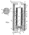
- FIG. 4 illustrates an alternative embodiment of the loading of substrates 32.
- the intervals 46 between adjacent substrates or between substrate and plate 40, 42 or cover 34 are provided with annular spacers 44 sealing the gaps 46.
- the reactive gas passage from the volume 36 to the volume 38 is only through the porosity of the substrates, which induces a fairly large pressure gradient between these two volumes.
- Figures 5 and 6 illustrate an alternative embodiment the loading of substrates that differs from the Figure 1 loading in that the substrates 32 are arranged in a plurality of annular stacks 31a, 31b, 31 c, 31 d, 31 e, 31 f, 31 g that are based on the support plate 40.
- the latter comprises a plurality of passages such as 41 has aligned with the internal volumes 36 to 36 g of cells and each cell is sealed at its top by a cover such as 34 a .
- the circulation of the reactive gas is through the heating zone 50 and the internal volumes of the batteries from which the gas passes into the volume 38 external to the batteries inside the charging zone 30.
- 7 batteries are represented in FIG. 6, the number of cells may of course be different, in particular greater than 7.
- Figure 7 illustrates another embodiment of the supply of a reactive gas furnace in the case of a charge formed of several annular batteries. This embodiment differs from that of FIG. 5 in that the cells are individually supplied with reactive gas.
- a plurality of passages are formed in the bottom 14 of the furnace, substantially aligned with the internal volumes of the stacks.
- FIG 7 only three passages 22 a, 22 c and 22 f are shown, aligned with the internal volumes 36 a, 36 c, 36 f of the batteries 32 a, 32 c and 32 f.
- reactive gas such as 62a, 62c, 62f are connected to the passages formed in the bottom of the furnace.
- the stacks supported by the tray 40 surmount individual heating zones such as 50 a , 50 c , 50 f .
- the heating zones are each delimited by a cylindrical vertical wall such as 56 a , 56 c , 56 f , a common bottom 54 and the plate 40.
- Pipes such as 58 a , 58 c , 58 f connect the openings formed in the furnace bottom to the different heating zones, through orifices formed in the bottom 54.
- Each heating zone comprises a plurality of perforated trays 52 arranged one above the other.
- Valves such as 64 a, 64 c, 64 f are mounted on the individual supply lines.
- the reactive gas from the preheater flows into a common line 62 to which the individual lines such as 62 a, 62 c, 62 f are connected.
- the batteries are then fed with reactive gas preheated to the same temperature.
- the individual lines such as 62 a, 62 c, 62 f may be connected to respective preheating devices. In this way, the preheating temperature of the reactant gas can be adjusted individually depending on the position in the furnace of the substrate stack to which the reactive gas is intended.
- the field of application of the invention is in no way limited to the production of C / C composite brake disks but also extends to the production of other C / C composite parts, for example diverging rocket engine nozzles, as shown in particular in the patent US 5 904 957 already cited.
- the invention can be implemented for producing parts of any type of thermostructural composite material, that is to say not only C / C composites but also CMCs.
- the composition of the reactive gas is chosen according to the particular nature of the ceramic matrix.
- Gaseous precursors of ceramic matrices are well known, for example methyltrichlorosilane (MTS) and hydrogen gas (H 2 ) to form a silicon carbide matrix.
- MTS methyltrichlorosilane
- H 2 hydrogen gas
Landscapes
- Chemical & Material Sciences (AREA)
- Engineering & Computer Science (AREA)
- Organic Chemistry (AREA)
- Materials Engineering (AREA)
- Ceramic Engineering (AREA)
- Chemical Kinetics & Catalysis (AREA)
- Mechanical Engineering (AREA)
- General Chemical & Material Sciences (AREA)
- Metallurgy (AREA)
- Structural Engineering (AREA)
- Composite Materials (AREA)
- Manufacturing & Machinery (AREA)
- Furnace Details (AREA)
- Chemical Vapour Deposition (AREA)
- Feeding, Discharge, Calcimining, Fusing, And Gas-Generation Devices (AREA)
- Separation Using Semi-Permeable Membranes (AREA)
- Crystals, And After-Treatments Of Crystals (AREA)
- Carbon And Carbon Compounds (AREA)
- Tunnel Furnaces (AREA)
- Manufacture, Treatment Of Glass Fibers (AREA)
- Physical Or Chemical Processes And Apparatus (AREA)
Claims (24)
- Verfahren zur Verdichtung von porösen Substraten durch eine Matrix, erhalten durch chemische Infiltration in Gasphase und der Verwendung eines reaktiven Gases, das wenigstens einen gasförmigen Vorläufer des Matrixmaterials enthält, wobei das Verfahren umfaßt:- die Beladung der zu verdichtenden Substrate in eine Ladezone eines Ofens,- das Heizen der Substrate in dem Ofen, um sie auf eine Temperatur zu bringen, bei der das gewünschte Matrixmaterial aus dem oder den gasförmigen Vorläufern gebildet wird, die in dem reaktiven Gas enthalten sind,- Einlaß des reaktiven Gases an einem Ende des Ofens, und- Heizen des reaktiven Gases nach Eintritt in den Ofen durch Durchgang in einer Gasheizzone, die in Fließrichtung des reaktiven Gases stromaufwärts der Ladezone in dem Ofen angeordnet ist,und dadurch gekennzeichnet, daß:- das reaktive Gas vor Eintritt in den Ofen vorgeheizt wird, um bei seinem Eintritt in den Ofen auf eine Zwischentemperatur zwischen der Umgebungstemperatur und der Heiztemperatur der Substrate gebracht zu sein.
- Verfahren nach Anspruch 1, dadurch gekennzeichnet, daß die Substrate auf eine Temperatur über 900°C gebracht werden und das reaktive Gas vorgewärmt wird, bevor es in den Ofen eintritt, um bei seinem Eintritt in den Ofen auf eine Temperatur von wenigstens gleich etwa 200°C gebracht zu sein.
- Verfahren nach Anspruch 2, dadurch gekennzeichnet, daß das reaktive Gas vorgewärmt wird vor Eintritt in den Ofen auf eine Temperatur höchstens gleich 800°C.
- Verfahren nach Anspruch 2, dadurch gekennzeichnet, daß das reaktive Gas vorgewärmt wird vor Eintritt in den Ofen auf eine Temperatur höchstens gleich 600°C.
- Verfahren nach der Ansprüche bis 4, dadurch gekennzeichnet, daß das reaktive Gas außerhalb des Ofens durch Durchgang durch einen Wärmetauscher vorgewärmt wird,
- Verfahren nach einem der Ansprüche 1 bis 5, dadurch gekennzeichnet, daß das reaktive Gas außerhalb des Ofens unter einem Druck im wesentlichen gleich jenem der in dem Ofen herrscht, vorgewärmt wird.
- Verfahren nach einem der Ansprüche 1 bis 5, dadurch gekennzeichnet, daß das reaktive Gas außerhalb des Ofens unter einem Druck über jenem, der in dem Ofen herrscht, vorgewärmt und vor seinem Eintritt in den Ofen entspannt wird,.
- Verfahren nach einem der Ansprüche 1 bis 7 zur Verdichtung von ringförmigen porösen Substraten für Bremsscheiben aus Karbon/Karbon-Kompositmaterial.
- Verfahren nach Anspruch 8, dadurch gekennzeichnet, daß die Substrate in den Ofen in einem oder mehreren ringförmigen Stapeln geladen werden und das reaktive Gas aus der Gasheizzone zu einem der beiden Volumina kanalisiert wird, die durch das oder die Innenvolumina der ringförmigen Stapel gebildet werden und durch das Volumen der Ladezone außerhalb des oder der ringförmigen Stapel und ein Gasstrom in dem anderen der beiden Volumina gesammelt wird, um aus dem Ofen heraus abgezogen zu werden.
- Verfahren nach Anspruch 9, dadurch gekennzeichnet, daß die Substrate gestapelt sind, indem man zwischen ihnen Verflüchtigungsdurchgänge einrichtet, die die beiden Volumina untereinander in Verbindung treten lassen.
- Verfahren nach Anspruch 9, dadurch gekennzeichnet, daß die Substrate ohne unter ihnen Verflüchtigungsdurchgänge einzurichten derart gestapelt werden, daß der Durchgang des reaktiven Gases von einem zum anderen der beiden Volumina lediglich durch die Porosität der Substrate geschieht.
- Verfahren nach einem der Ansprüche 9 bis 11, dadurch gekennzeichnet, daß die ringförmigen Stapel mit reaktivem Gas der jeweiligen Durchgänge einer Wand des Ofens gespeist werden.
- Verfahren nach Anspruch 12, dadurch gekennzeichnet, daß die Heiztemperatur des reaktiven Gases, das die Substratstapel speist, individuell für jeden Stapel eingestellt wird.
- Anlage zur Verdichtung von porösen Substraten durch chemische Infiltration in Dampfphase, umfassend einen Ofen (10), eine Ladezone (30) für Substrate in dem Ofen, Heizmittel (12) für Substrate in der Ladezone, wenigstens einen Eingang (22; 22a, 22c, 22f) von reaktivem Gas in dem Ofen und wenigstens eine Zone (50; 50a, 50c, 50f) zum Heizen des Gases, angeordnet in dem Ofen zwischen dem Eingang des reaktiven Gases und der Ladezone, dadurch gekennzeichnet, daß die Anlage außerdem wenigstens eine Vorrichtung (60; 80) zum Vorheizen von Gas umfaßt, angeordnet außerhalb des Ofens (10) und verbunden mit wenigstens einem Eingang von reaktivem Gas in dem Ofen derart, daß das reaktive Gas vor seinem Eintritt in den Ofen vorgewärmt wird.
- Anlage nach Anspruch 14, dadurch gekennzeichnet, daß die Vorrichtung zum Vorwärmen wenigstens ein Rohr mit Strömungsdurchgang (66) umfaßt, das in der Leitung zur Zufuhr des reaktiven Gases am Eintritt des reaktiven Gases in den Ofen angeordnet ist.
- Anlage nach Anspruch 14, dadurch gekennzeichnet, daß die Varwärmvorrichtung eine Gasheizung (80) umfaßt, die von wenigstens einer Leitung zur Zirkulation des reaktiven vorzuwärmenden Gases durchlaufen wird.
- Anlage nach Anspruch 16, dadurch gekennzeichnet, daß die Heizung mit einem Austritt (24) des Gasstroms aus dem Ofen heraus verbunden ist, um wenigstens einen Teil des Gasstroms als Brenngas für die Heizung zu verwenden.
- Anlage nach Anspruch 14, dadurch gekennzeichnet, daß die Vorwärmvorrichtung einen Ofen mit elektrischer Heizung umfaßt, der durch wenigstens ein Rohr zur Zirkulation des reaktiven vorzuwärmenden Gases durchlaufen wird.
- Anlage nach einem der Ansprüche 14 bis 18, dadurch gekennzeichnet, daß sie eine Entspannungsvorrichtung zwischen der Heizvorrichtung und dem Eintritt eines reaktiven Gases in den Ofen umfaßt.
- Anlage nach einem der Ansprüche 14 bis 19, dadurch gekennzeichnet, daß die Vorwärmvorrichtung Mittel zur Temperaturregelung umfaßt.
- Anlage nach einem der Ansprüche 14 bis 20 zur Verdichtung von ringförmigen Substraten, die in einer Vielzahl von Stapeln angeordnet sind, dadurch gekennzeichnet, daß sie eine Mehrzahl von Heizzonen (50a, 50c, 50f) umfaßt, die jede zwischen einem jeweiligen Eintritt (22a, 22c, 22f) von reaktivem Gas in den Ofen und einem jeweiligen Ort eines ringförmigen Stapels in der Ladezone angeordnet sind.
- Anlage nach Anspruch 21, dadurch gekennzeichnet, daß sie eine Vielzahl von individuellen Leitungen zur Versorgung mit reaktivem vorgewärmten Gas (62a, 62c, 62f) umfaßt, die mit Eingängen von reaktivem Gas in den Ofen verbunden sind.
- Anlage nach Anspruch 22, dadurch gekennzeichnet, daß die individuellen Versorgungsleitungen (62a, 62c, 62f) mit einer Vorwärmvorrichtung durch eine gemeinsame Leitung verbunden sind.
- Anlage nach Anspruch 22, dadurch gekennzeichnet, daß die individuellen Versorgungsleitungen mit jeweiligen Vorrichtungen zum Vorheizen von reaktivem Gas verbunden sind.
Applications Claiming Priority (3)
| Application Number | Priority Date | Filing Date | Title |
|---|---|---|---|
| US10/034,848 US6953605B2 (en) | 2001-12-26 | 2001-12-26 | Method for densifying porous substrates by chemical vapour infiltration with preheated gas |
| US34848 | 2001-12-26 | ||
| PCT/FR2002/004554 WO2003056059A1 (fr) | 2001-12-26 | 2002-12-24 | Procede et installation de densification de substrats poreux par infiltration chimique en phase gazeuse |
Publications (2)
| Publication Number | Publication Date |
|---|---|
| EP1458902A1 EP1458902A1 (de) | 2004-09-22 |
| EP1458902B1 true EP1458902B1 (de) | 2006-09-27 |
Family
ID=21878976
Family Applications (1)
| Application Number | Title | Priority Date | Filing Date |
|---|---|---|---|
| EP02799114A Expired - Lifetime EP1458902B1 (de) | 2001-12-26 | 2002-12-24 | Verfahren und vorrichtung zur verdichtung poröser substrate mittels chemischer dampfinfiltration |
Country Status (17)
| Country | Link |
|---|---|
| US (2) | US6953605B2 (de) |
| EP (1) | EP1458902B1 (de) |
| JP (1) | JP4426302B2 (de) |
| KR (1) | KR100896854B1 (de) |
| CN (1) | CN100371493C (de) |
| AT (1) | ATE340880T1 (de) |
| AU (1) | AU2002364339B2 (de) |
| BR (1) | BR0215313B1 (de) |
| CA (1) | CA2471672C (de) |
| DE (1) | DE60215048T2 (de) |
| ES (1) | ES2274121T3 (de) |
| HU (1) | HUP0402078A2 (de) |
| IL (1) | IL162659A0 (de) |
| MX (1) | MXPA04006329A (de) |
| RU (1) | RU2319682C2 (de) |
| UA (1) | UA78733C2 (de) |
| WO (1) | WO2003056059A1 (de) |
Cited By (1)
| Publication number | Priority date | Publication date | Assignee | Title |
|---|---|---|---|---|
| FR3007511A1 (fr) * | 2013-06-19 | 2014-12-26 | Herakles | Installation pour traitements thermiques de produits en materiau composite comprenant des moyens de mesure de temperature delocalises |
Families Citing this family (51)
| Publication number | Priority date | Publication date | Assignee | Title |
|---|---|---|---|---|
| US7476419B2 (en) * | 1998-10-23 | 2009-01-13 | Goodrich Corporation | Method for measurement of weight during a CVI/CVD process |
| US6669988B2 (en) * | 2001-08-20 | 2003-12-30 | Goodrich Corporation | Hardware assembly for CVI/CVD processes |
| US20040255862A1 (en) * | 2001-02-26 | 2004-12-23 | Lee Chung J. | Reactor for producing reactive intermediates for low dielectric constant polymer thin films |
| US6758909B2 (en) * | 2001-06-05 | 2004-07-06 | Honeywell International Inc. | Gas port sealing for CVD/CVI furnace hearth plates |
| FR2834713B1 (fr) * | 2002-01-15 | 2004-04-02 | Snecma Moteurs | Procede et installation pour la densification de substrats par infiltration chimique en phase vapeur |
| US20050158468A1 (en) * | 2004-01-20 | 2005-07-21 | John Gaffney | Method for manufacturing carbon composites |
| US20060201426A1 (en) * | 2004-05-25 | 2006-09-14 | Lee Chung J | Reactor for Producing Reactive Intermediates for Transport Polymerization |
| US7799375B2 (en) * | 2004-06-30 | 2010-09-21 | Poco Graphite, Inc. | Process for the manufacturing of dense silicon carbide |
| US7332195B2 (en) * | 2004-08-26 | 2008-02-19 | Honeywell International Inc. | Chemical vapor deposition method |
| FR2881145B1 (fr) * | 2005-01-24 | 2007-11-23 | Snecma Propulsion Solide Sa | Procede d'infiltration chimique en phase gazeuse pour la densification de substrats poreux par du carbone pyrolytique |
| FR2882064B1 (fr) | 2005-02-17 | 2007-05-11 | Snecma Propulsion Solide Sa | Procede de densification de substrats poreux minces par infiltration chimique en phase vapeur et dispositif de chargement de tels substrats |
| US20060194060A1 (en) * | 2005-02-25 | 2006-08-31 | Honeywell International | Furnace spacers for spacing preforms in a furnace |
| US20060194059A1 (en) * | 2005-02-25 | 2006-08-31 | Honeywell International Inc. | Annular furnace spacers and method of using same |
| US20060274474A1 (en) * | 2005-06-01 | 2006-12-07 | Lee Chung J | Substrate Holder |
| US20070014990A1 (en) * | 2005-07-14 | 2007-01-18 | Honeywell International Inc. | Support structure for radiative heat transfer |
| US20070184179A1 (en) * | 2006-02-09 | 2007-08-09 | Akshay Waghray | Methods and apparatus to monitor a process of depositing a constituent of a multi-constituent gas during production of a composite brake disc |
| FR2897422B1 (fr) | 2006-02-14 | 2008-05-16 | Messier Bugatti Sa | Dispositif d'etancheite pour une entree de gaz d'un four ou analogue |
| US7771194B2 (en) * | 2006-05-26 | 2010-08-10 | Honeywell International Inc. | Gas preheater for chemical vapor processing furnace having circuitous passages |
| JP5205554B2 (ja) * | 2006-10-29 | 2013-06-05 | メシエ−ブガッティ−ドウティ | 多孔質物品を高密度化する方法 |
| FR2924426B1 (fr) * | 2007-11-30 | 2011-06-03 | Messier Bugatti | Procede de fabrication de pieces en materiau composite a renfort en fibres de carbone. |
| JP5730496B2 (ja) * | 2009-05-01 | 2015-06-10 | 株式会社日立国際電気 | 熱処理装置、半導体デバイスの製造方法および基板処理方法 |
| US8177884B2 (en) * | 2009-05-20 | 2012-05-15 | United Technologies Corporation | Fuel deoxygenator with porous support plate |
| US20110064891A1 (en) * | 2009-09-16 | 2011-03-17 | Honeywell International Inc. | Methods of rapidly densifying complex-shaped, asymmetrical porous structures |
| CN102713001B (zh) | 2009-11-18 | 2014-03-05 | 瑞科硅公司 | 流化床反应器 |
| US20120090805A1 (en) * | 2010-10-18 | 2012-04-19 | Uzialko Stanislaw P | Systems and methods for a thermistor furnace |
| FR2993044B1 (fr) * | 2012-07-04 | 2014-08-08 | Herakles | Dispositif de chargement et installation pour la densification de preformes poreuses tronconiques et empilables |
| FR2993555B1 (fr) * | 2012-07-19 | 2015-02-20 | Herakles | Installation d'infiltration chimique en phase vapeur a haute capacite de chargement |
| US11326255B2 (en) * | 2013-02-07 | 2022-05-10 | Uchicago Argonne, Llc | ALD reactor for coating porous substrates |
| US9523149B2 (en) | 2013-03-14 | 2016-12-20 | Rolls-Royce Corporation | Rapid ceramic matrix composite production method |
| FR3018526B1 (fr) * | 2014-03-14 | 2021-06-11 | Herakles | Installation de densification cvi comprenant une zone de prechauffage a forte capacite |
| US10648075B2 (en) * | 2015-03-23 | 2020-05-12 | Goodrich Corporation | Systems and methods for chemical vapor infiltration and densification of porous substrates |
| WO2017033053A1 (en) | 2015-08-21 | 2017-03-02 | Flisom Ag | Homogeneous linear evaporation source |
| TWI624554B (zh) * | 2015-08-21 | 2018-05-21 | 弗里松股份有限公司 | 蒸發源 |
| RU2607401C1 (ru) * | 2015-09-25 | 2017-01-10 | Олег Викторович Барзинский | Способ получения углерод-углеродого композиционного материала |
| CN105463410B (zh) * | 2015-12-15 | 2018-09-21 | 西安鑫垚陶瓷复合材料有限公司 | 一种用于开口容器的cvi致密化的方法及气体管路结构 |
| US10407769B2 (en) * | 2016-03-18 | 2019-09-10 | Goodrich Corporation | Method and apparatus for decreasing the radial temperature gradient in CVI/CVD furnaces |
| US20200386723A1 (en) * | 2017-12-05 | 2020-12-10 | Mécanique Analytique Inc. | Gas chromatography modular oven |
| CN108048817A (zh) * | 2017-12-12 | 2018-05-18 | 湖南顶立科技有限公司 | 一种化学气相沉积炉 |
| FR3084892B1 (fr) | 2018-08-10 | 2020-11-06 | Safran Ceram | Procede de densification par infiltration chimique en phase gazeuse de substrats annulaire poreux |
| US11111578B1 (en) | 2020-02-13 | 2021-09-07 | Uchicago Argonne, Llc | Atomic layer deposition of fluoride thin films |
| CN113683436B (zh) * | 2021-08-27 | 2022-09-16 | 清华大学 | 一种进气组件、气相沉积装置及其复合材料制备方法 |
| US12065738B2 (en) | 2021-10-22 | 2024-08-20 | Uchicago Argonne, Llc | Method of making thin films of sodium fluorides and their derivatives by ALD |
| FR3128956B1 (fr) * | 2021-11-10 | 2023-11-03 | Safran Ceram | Procédé de densification par infiltration chimique en phase vapeur |
| CN114225843B (zh) * | 2021-12-06 | 2022-08-05 | 中南大学 | 一种限域定向流动全饱和渗透反应器及制备炭/炭复合材料刹车盘的方法 |
| FR3130276A1 (fr) * | 2021-12-15 | 2023-06-16 | Safran Ceramics | Installation de traitement thermochimique et procédé de fabrication d’une pièce de friction en matériau composite |
| US11932941B1 (en) | 2021-12-29 | 2024-03-19 | Rolls-Royce High Temperature Composites, Inc. | Load assemblies for loading parts in a furnace |
| US12000046B1 (en) * | 2021-12-29 | 2024-06-04 | Rolls-Royce High Temperature Composites, Inc. | Load assemblies for loading parts in a furnace |
| US12078417B1 (en) | 2021-12-29 | 2024-09-03 | Rolls-Royce High Temperature Composites, Inc. | Load assemblies for loading parts in a furnace |
| US11901169B2 (en) | 2022-02-14 | 2024-02-13 | Uchicago Argonne, Llc | Barrier coatings |
| FR3132718A1 (fr) * | 2022-02-16 | 2023-08-18 | Safran Landing Systems | Procédé de densification par infiltration chimique en phase gazeuse avec des plateaux monopiles pour un flux semi-forcé |
| CN119082862B (zh) * | 2024-11-07 | 2025-05-27 | 洛阳中硅高科技有限公司 | 多晶碳化硅棒及其制备装置和方法以及多晶碳化硅粉体 |
Family Cites Families (47)
| Publication number | Priority date | Publication date | Assignee | Title |
|---|---|---|---|---|
| US3663283A (en) * | 1969-10-02 | 1972-05-16 | Richard A Hebert | Process and apparatus for the production of finely-divided metal oxides |
| JPS5222012A (en) | 1975-08-12 | 1977-02-19 | Matsushita Electric Industrial Co Ltd | Manufacture of nonnburnt carbon rods |
| US4141696A (en) | 1978-04-28 | 1979-02-27 | Texaco Inc. | Process for gas cleaning with reclaimed water and apparatus for water reclamation |
| US4416748A (en) | 1981-09-08 | 1983-11-22 | Concord Scientific Corporation | Process for reduction of the content of SO2 and/or NOx in flue gas |
| US4582632A (en) | 1983-04-11 | 1986-04-15 | Kabushiki Kaisha Kobe Seiko Sho | Non-permeable carbonaceous formed bodies and method for producing same |
| US4738272A (en) | 1984-05-21 | 1988-04-19 | Mcconnell Christopher F | Vessel and system for treating wafers with fluids |
| JPS6220309A (ja) | 1985-07-18 | 1987-01-28 | Nec Corp | 光照射炉 |
| JPS62249423A (ja) | 1986-04-23 | 1987-10-30 | Hitachi Ltd | 処理装置 |
| US4920017A (en) | 1986-11-20 | 1990-04-24 | Electric Power Research Institute, Inc. | Porous and porous-nonporous composites for battery electrodes |
| US4835074A (en) | 1987-09-25 | 1989-05-30 | The Electrosynthesis Company, Inc. | Modified carbons and electrochemical cells containing the same |
| US4957593A (en) | 1989-03-07 | 1990-09-18 | University Of Connecticut | Modified composite electrodes with renewable surface for electrochemical applications and method of making same |
| US5225378A (en) | 1990-11-16 | 1993-07-06 | Tokyo Electron Limited | Method of forming a phosphorus doped silicon film |
| US5362228A (en) * | 1991-11-04 | 1994-11-08 | Societe Europeenne De Propulsion | Apparatus for preheating a flow of gas in an installation for chemical vapor infiltration, and a densification method using the apparatus |
| JP2987663B2 (ja) | 1992-03-10 | 1999-12-06 | 株式会社日立製作所 | 基板処理装置 |
| US5254374A (en) * | 1992-04-08 | 1993-10-19 | The United States Of America As Represented By The United States Department Of Energy | Chemical vapor infiltration using microwave energy |
| US5567267A (en) | 1992-11-20 | 1996-10-22 | Tokyo Electron Limited | Method of controlling temperature of susceptor |
| JPH0828335B2 (ja) | 1992-11-30 | 1996-03-21 | 株式会社半導体プロセス研究所 | 半導体装置の製造装置 |
| US5348774A (en) * | 1993-08-11 | 1994-09-20 | Alliedsignal Inc. | Method of rapidly densifying a porous structure |
| FR2711646B1 (fr) * | 1993-10-27 | 1996-02-09 | Europ Propulsion | Procédé d'infiltration chimique en phase vapeur d'une matrice pyrocarbone au sein d'un substrat poreux avec établissement d'un gradient de température dans le substrat. |
| FR2711647B1 (fr) * | 1993-10-27 | 1996-01-19 | Europ Propulsion | Procédé d'infiltration chimique en phase vapeur d'un matériau au sein d'un substrat poreux à température de surface contrôlée. |
| FR2714076B1 (fr) * | 1993-12-16 | 1996-03-15 | Europ Propulsion | Procédé de densification de substrats poreux par infiltration chimique en phase vapeur de carbure de silicium. |
| US5582802A (en) | 1994-07-05 | 1996-12-10 | Spokoyny; Felix E. | Catalytic sulfur trioxide flue gas conditioning |
| ATE215518T1 (de) * | 1994-11-16 | 2002-04-15 | Goodrich Co B F | Vorrichtung zur druckfeld cvd/cvi, verfahren und produkt |
| US5480678A (en) | 1994-11-16 | 1996-01-02 | The B. F. Goodrich Company | Apparatus for use with CVI/CVD processes |
| FR2727692A1 (fr) | 1994-12-05 | 1996-06-07 | Europ Propulsion | Dispositif d'extraction de gaz pour four d'infiltration ou depot chimique en phase vapeur dans une installation de fabrication de pieces en materiau composite |
| FR2732677B1 (fr) * | 1995-04-07 | 1997-06-27 | Europ Propulsion | Procede d'infiltration chimique en phase vapeur avec parametres d'infiltration variables |
| FR2733254B1 (fr) | 1995-04-18 | 1997-07-18 | Europ Propulsion | Procede d'infiltration chimique en phase vapeur pour la densification de substrats poreux disposes en piles annulaires |
| RU2096707C1 (ru) * | 1995-09-27 | 1997-11-20 | Российско-швейцарское совместное предприятие Акционерное общество закрытого типа "АМКО" | Вращающаяся печь для дегидрации фторида алюминия |
| US5707432A (en) | 1996-06-14 | 1998-01-13 | Cabot Corporation | Modified carbon products and inks and coatings containing modified carbon products |
| FR2754813B1 (fr) * | 1996-10-18 | 1999-01-15 | Europ Propulsion | Densification de substrats poreux disposes en piles annulaires par infiltration chimique en phase vapeur a gradient de temperature |
| US5840414A (en) | 1996-11-15 | 1998-11-24 | International Fuel Cells, Inc. | Porous carbon body with increased wettability by water |
| WO1998028462A1 (de) | 1996-12-24 | 1998-07-02 | Widia Gmbh | Verbundkörper, bestehend aus einem hartmetall-, cermet- oder keramiksubstratkörper und verfahren zu seiner herstellung |
| US5942347A (en) | 1997-05-20 | 1999-08-24 | Institute Of Gas Technology | Proton exchange membrane fuel cell separator plate |
| US20030049372A1 (en) | 1997-08-11 | 2003-03-13 | Cook Robert C. | High rate deposition at low pressures in a small batch reactor |
| US6007330A (en) | 1998-03-12 | 1999-12-28 | Cosmos Factory, Inc. | Liquid precursor delivery system |
| EP1066352B2 (de) | 1998-04-03 | 2008-10-01 | Cabot Corporation | Modifizierte pigmente mit verbesserten dispergierenden eigenschaften |
| US6024848A (en) | 1998-04-15 | 2000-02-15 | International Fuel Cells, Corporation | Electrochemical cell with a porous support plate |
| FR2784695B1 (fr) * | 1998-10-20 | 2001-11-02 | Snecma | Densification de structures poreuses par infiltration chimique en phase vapeur |
| US6440220B1 (en) | 1998-10-23 | 2002-08-27 | Goodrich Corporation | Method and apparatus for inhibiting infiltration of a reactive gas into porous refractory insulation |
| US6144802A (en) | 1999-06-29 | 2000-11-07 | Hyundai Electronics Industries Co., Ltd. | Fluid heater for semiconductor device |
| JP4391713B2 (ja) | 1999-07-02 | 2009-12-24 | 東京エレクトロン株式会社 | 半導体製造設備 |
| US6258476B1 (en) | 1999-09-02 | 2001-07-10 | International Fuel Cells, Llc | Porous carbon body with increased wettability by water |
| KR100783841B1 (ko) | 2000-05-31 | 2007-12-10 | 동경 엘렉트론 주식회사 | 열처리 시스템 |
| US20030091891A1 (en) | 2001-01-16 | 2003-05-15 | Tomoaki Yoshida | Catalyst composition for cell, gas diffusion layer, and fuel cell comprising the same |
| US6645287B2 (en) | 2001-04-27 | 2003-11-11 | Cabot Corporation | Coating compositions comprising high t-area carbon products |
| US6787029B2 (en) | 2001-08-31 | 2004-09-07 | Cabot Corporation | Material for chromatography |
| US6572371B1 (en) * | 2002-05-06 | 2003-06-03 | Messier-Bugatti | Gas preheater and process for controlling distribution of preheated reactive gas in a CVI furnace for densification of porous annular substrates |
-
2001
- 2001-12-26 US US10/034,848 patent/US6953605B2/en not_active Expired - Lifetime
-
2002
- 2002-12-24 CN CNB028260562A patent/CN100371493C/zh not_active Expired - Lifetime
- 2002-12-24 ES ES02799114T patent/ES2274121T3/es not_active Expired - Lifetime
- 2002-12-24 MX MXPA04006329A patent/MXPA04006329A/es active IP Right Grant
- 2002-12-24 RU RU2004118418/02A patent/RU2319682C2/ru active
- 2002-12-24 CA CA2471672A patent/CA2471672C/en not_active Expired - Fee Related
- 2002-12-24 KR KR1020047010048A patent/KR100896854B1/ko not_active Expired - Fee Related
- 2002-12-24 JP JP2003556573A patent/JP4426302B2/ja not_active Expired - Fee Related
- 2002-12-24 HU HU0402078A patent/HUP0402078A2/hu unknown
- 2002-12-24 IL IL16265902A patent/IL162659A0/xx not_active IP Right Cessation
- 2002-12-24 DE DE60215048T patent/DE60215048T2/de not_active Expired - Lifetime
- 2002-12-24 AU AU2002364339A patent/AU2002364339B2/en not_active Ceased
- 2002-12-24 WO PCT/FR2002/004554 patent/WO2003056059A1/fr not_active Ceased
- 2002-12-24 AT AT02799114T patent/ATE340880T1/de active
- 2002-12-24 EP EP02799114A patent/EP1458902B1/de not_active Expired - Lifetime
- 2002-12-24 BR BRPI0215313-0A patent/BR0215313B1/pt not_active IP Right Cessation
- 2002-12-24 UA UA20040605015A patent/UA78733C2/uk unknown
-
2003
- 2003-04-16 US US10/417,037 patent/US20030205203A1/en not_active Abandoned
Cited By (1)
| Publication number | Priority date | Publication date | Assignee | Title |
|---|---|---|---|---|
| FR3007511A1 (fr) * | 2013-06-19 | 2014-12-26 | Herakles | Installation pour traitements thermiques de produits en materiau composite comprenant des moyens de mesure de temperature delocalises |
Also Published As
| Publication number | Publication date |
|---|---|
| CA2471672A1 (en) | 2003-07-10 |
| CN100371493C (zh) | 2008-02-27 |
| HUP0402078A2 (hu) | 2005-01-28 |
| IL162659A0 (en) | 2005-11-20 |
| KR100896854B1 (ko) | 2009-05-12 |
| MXPA04006329A (es) | 2004-10-04 |
| BR0215313B1 (pt) | 2011-11-29 |
| ES2274121T3 (es) | 2007-05-16 |
| KR20040071754A (ko) | 2004-08-12 |
| DE60215048D1 (de) | 2006-11-09 |
| CA2471672C (en) | 2011-03-22 |
| BR0215313A (pt) | 2004-10-19 |
| EP1458902A1 (de) | 2004-09-22 |
| AU2002364339B2 (en) | 2008-09-04 |
| WO2003056059A1 (fr) | 2003-07-10 |
| AU2002364339A1 (en) | 2003-07-15 |
| ATE340880T1 (de) | 2006-10-15 |
| RU2319682C2 (ru) | 2008-03-20 |
| US20030118728A1 (en) | 2003-06-26 |
| JP4426302B2 (ja) | 2010-03-03 |
| JP2005512940A (ja) | 2005-05-12 |
| CN1608142A (zh) | 2005-04-20 |
| UA78733C2 (en) | 2007-04-25 |
| DE60215048T2 (de) | 2007-05-10 |
| US20030205203A1 (en) | 2003-11-06 |
| US6953605B2 (en) | 2005-10-11 |
| RU2004118418A (ru) | 2005-06-10 |
Similar Documents
| Publication | Publication Date | Title |
|---|---|---|
| EP1458902A1 (de) | Verfahren und vorrichtung zur verdichtung poröser substrate mittels chemischer dampfinfiltration | |
| EP1851358B1 (de) | Verfahren zur verdichtung von dünnen porösen substraten mittels chemischer infiltration in der dampfphase und vorrichtung zur beladung derartiger substrate | |
| EP0821744B1 (de) | Verfahren zur chemischen infiltration in der gasphase, zur verdichtung poröser rotationssymmetrischer substratstapeln | |
| EP1466031B1 (de) | Verfahren und vorrichtung zur verdichtung von substraten mittels chemischer gasphaseninfiltration | |
| EP1370707B1 (de) | Verfahren zur verdichtung poröser substrate, mit einem zentralen durchgang, mittels chemischer dampfinfiltration | |
| EP0946461B1 (de) | Verdichtung ringförmig angeordneter poröser substrate mittels chemicher dampfinfiltration mit temperaturgradient | |
| EP3117020B1 (de) | Cvi-verdichtungsausrüstung mit hochkapazitivem vorwärmbereich | |
| EP0734464B1 (de) | Verfahren zum abdichten poröser substrate | |
| EP2761053B1 (de) | Ladevorrichtung zur verdichtung mittels chemischer infiltration in der dampf phase in gerichteter strömung von dreidimensionalen porösen substraten | |
| EP2110458B1 (de) | Wärmebehandlungsofen mit Induktionsheizung | |
| EP2870272A1 (de) | Ladevorrichtung und anlage zur verdichtung stapelbarer poröser vorformen in kegelstumpfform | |
| EP2875167A1 (de) | Chemische gasphaseninfiltrationsvorrichtung mit hoher beladungskapazität | |
| EP0820424B1 (de) | Verfahren zur chemischen dampfinfiltration eines aus kohlenstoff und silicium und/oder bor zusammengesetzten materials | |
| WO2020212168A1 (fr) | Installation de densification cvi | |
| WO2023105139A1 (fr) | Installation d'infiltration chimique en phase gazeuse a double chambre de reaction | |
| EP4430225B1 (de) | Verfahren zur verdichtung durch chemische dampfinfiltration | |
| EP4479574B1 (de) | Verdichtungsverfahren für chemische dampfinfiltration mit einem werkzeug von multipile-platten für halbverstärkten fluss | |
| FR3010995A1 (fr) | Installation industrielle pour infiltration chimique en phase gazeuse de substrats poreux avec circuit de refroidissement accelere | |
| FR3141700A1 (fr) | Installation d’infiltration chimique en phase gazeuse à double traitement |
Legal Events
| Date | Code | Title | Description |
|---|---|---|---|
| PUAI | Public reference made under article 153(3) epc to a published international application that has entered the european phase |
Free format text: ORIGINAL CODE: 0009012 |
|
| 17P | Request for examination filed |
Effective date: 20040617 |
|
| AK | Designated contracting states |
Kind code of ref document: A1 Designated state(s): AT BE BG CH CY CZ DE DK EE ES FI FR GB GR IE IT LI LU MC NL PT SE SI SK TR |
|
| AX | Request for extension of the european patent |
Extension state: AL LT LV MK RO |
|
| 17Q | First examination report despatched |
Effective date: 20041019 |
|
| RIN1 | Information on inventor provided before grant (corrected) |
Inventor name: SION, ERIC Inventor name: BAUDRY, YVAN Inventor name: DELPERIER, BERNARD |
|
| GRAP | Despatch of communication of intention to grant a patent |
Free format text: ORIGINAL CODE: EPIDOSNIGR1 |
|
| GRAS | Grant fee paid |
Free format text: ORIGINAL CODE: EPIDOSNIGR3 |
|
| GRAA | (expected) grant |
Free format text: ORIGINAL CODE: 0009210 |
|
| AK | Designated contracting states |
Kind code of ref document: B1 Designated state(s): AT BE BG CH CY CZ DE DK EE ES FI FR GB GR IE IT LI LU MC NL PT SE SI SK TR |
|
| PG25 | Lapsed in a contracting state [announced via postgrant information from national office to epo] |
Ref country code: CZ Free format text: LAPSE BECAUSE OF FAILURE TO SUBMIT A TRANSLATION OF THE DESCRIPTION OR TO PAY THE FEE WITHIN THE PRESCRIBED TIME-LIMIT Effective date: 20060927 Ref country code: SI Free format text: LAPSE BECAUSE OF FAILURE TO SUBMIT A TRANSLATION OF THE DESCRIPTION OR TO PAY THE FEE WITHIN THE PRESCRIBED TIME-LIMIT Effective date: 20060927 Ref country code: NL Free format text: LAPSE BECAUSE OF FAILURE TO SUBMIT A TRANSLATION OF THE DESCRIPTION OR TO PAY THE FEE WITHIN THE PRESCRIBED TIME-LIMIT Effective date: 20060927 Ref country code: SK Free format text: LAPSE BECAUSE OF FAILURE TO SUBMIT A TRANSLATION OF THE DESCRIPTION OR TO PAY THE FEE WITHIN THE PRESCRIBED TIME-LIMIT Effective date: 20060927 Ref country code: FI Free format text: LAPSE BECAUSE OF FAILURE TO SUBMIT A TRANSLATION OF THE DESCRIPTION OR TO PAY THE FEE WITHIN THE PRESCRIBED TIME-LIMIT Effective date: 20060927 Ref country code: IE Free format text: LAPSE BECAUSE OF FAILURE TO SUBMIT A TRANSLATION OF THE DESCRIPTION OR TO PAY THE FEE WITHIN THE PRESCRIBED TIME-LIMIT Effective date: 20060927 |
|
| REG | Reference to a national code |
Ref country code: GB Ref legal event code: FG4D Free format text: NOT ENGLISH |
|
| REG | Reference to a national code |
Ref country code: CH Ref legal event code: EP |
|
| REG | Reference to a national code |
Ref country code: IE Ref legal event code: FG4D Free format text: LANGUAGE OF EP DOCUMENT: FRENCH |
|
| REF | Corresponds to: |
Ref document number: 60215048 Country of ref document: DE Date of ref document: 20061109 Kind code of ref document: P |
|
| PG25 | Lapsed in a contracting state [announced via postgrant information from national office to epo] |
Ref country code: DK Free format text: LAPSE BECAUSE OF FAILURE TO SUBMIT A TRANSLATION OF THE DESCRIPTION OR TO PAY THE FEE WITHIN THE PRESCRIBED TIME-LIMIT Effective date: 20061227 Ref country code: SE Free format text: LAPSE BECAUSE OF FAILURE TO SUBMIT A TRANSLATION OF THE DESCRIPTION OR TO PAY THE FEE WITHIN THE PRESCRIBED TIME-LIMIT Effective date: 20061227 Ref country code: BG Free format text: LAPSE BECAUSE OF FAILURE TO SUBMIT A TRANSLATION OF THE DESCRIPTION OR TO PAY THE FEE WITHIN THE PRESCRIBED TIME-LIMIT Effective date: 20061227 |
|
| PG25 | Lapsed in a contracting state [announced via postgrant information from national office to epo] |
Ref country code: CH Free format text: LAPSE BECAUSE OF NON-PAYMENT OF DUE FEES Effective date: 20061231 Ref country code: LI Free format text: LAPSE BECAUSE OF NON-PAYMENT OF DUE FEES Effective date: 20061231 Ref country code: MC Free format text: LAPSE BECAUSE OF NON-PAYMENT OF DUE FEES Effective date: 20061231 Ref country code: BE Free format text: LAPSE BECAUSE OF NON-PAYMENT OF DUE FEES Effective date: 20061231 |
|
| NLV1 | Nl: lapsed or annulled due to failure to fulfill the requirements of art. 29p and 29m of the patents act | ||
| PG25 | Lapsed in a contracting state [announced via postgrant information from national office to epo] |
Ref country code: PT Free format text: LAPSE BECAUSE OF FAILURE TO SUBMIT A TRANSLATION OF THE DESCRIPTION OR TO PAY THE FEE WITHIN THE PRESCRIBED TIME-LIMIT Effective date: 20070313 |
|
| GBT | Gb: translation of ep patent filed (gb section 77(6)(a)/1977) |
Effective date: 20070309 |
|
| REG | Reference to a national code |
Ref country code: IE Ref legal event code: FD4D |
|
| REG | Reference to a national code |
Ref country code: ES Ref legal event code: FG2A Ref document number: 2274121 Country of ref document: ES Kind code of ref document: T3 |
|
| REG | Reference to a national code |
Ref country code: CH Ref legal event code: PL |
|
| PLBE | No opposition filed within time limit |
Free format text: ORIGINAL CODE: 0009261 |
|
| STAA | Information on the status of an ep patent application or granted ep patent |
Free format text: STATUS: NO OPPOSITION FILED WITHIN TIME LIMIT |
|
| 26N | No opposition filed |
Effective date: 20070628 |
|
| BERE | Be: lapsed |
Owner name: MESSIER-BUGATTI Effective date: 20061231 |
|
| PG25 | Lapsed in a contracting state [announced via postgrant information from national office to epo] |
Ref country code: GR Free format text: LAPSE BECAUSE OF FAILURE TO SUBMIT A TRANSLATION OF THE DESCRIPTION OR TO PAY THE FEE WITHIN THE PRESCRIBED TIME-LIMIT Effective date: 20061228 |
|
| PG25 | Lapsed in a contracting state [announced via postgrant information from national office to epo] |
Ref country code: EE Free format text: LAPSE BECAUSE OF FAILURE TO SUBMIT A TRANSLATION OF THE DESCRIPTION OR TO PAY THE FEE WITHIN THE PRESCRIBED TIME-LIMIT Effective date: 20060927 |
|
| PG25 | Lapsed in a contracting state [announced via postgrant information from national office to epo] |
Ref country code: TR Free format text: LAPSE BECAUSE OF FAILURE TO SUBMIT A TRANSLATION OF THE DESCRIPTION OR TO PAY THE FEE WITHIN THE PRESCRIBED TIME-LIMIT Effective date: 20060927 Ref country code: LU Free format text: LAPSE BECAUSE OF NON-PAYMENT OF DUE FEES Effective date: 20061224 |
|
| PG25 | Lapsed in a contracting state [announced via postgrant information from national office to epo] |
Ref country code: CY Free format text: LAPSE BECAUSE OF FAILURE TO SUBMIT A TRANSLATION OF THE DESCRIPTION OR TO PAY THE FEE WITHIN THE PRESCRIBED TIME-LIMIT Effective date: 20060927 |
|
| PGFP | Annual fee paid to national office [announced via postgrant information from national office to epo] |
Ref country code: IT Payment date: 20101223 Year of fee payment: 9 |
|
| PGFP | Annual fee paid to national office [announced via postgrant information from national office to epo] |
Ref country code: ES Payment date: 20111222 Year of fee payment: 10 |
|
| REG | Reference to a national code |
Ref country code: FR Ref legal event code: CA Effective date: 20120321 Ref country code: FR Ref legal event code: CD Owner name: MESSIER-BUGATTI-DOWTY, FR Effective date: 20120321 |
|
| REG | Reference to a national code |
Ref country code: DE Ref legal event code: R082 Ref document number: 60215048 Country of ref document: DE Representative=s name: CBDL PATENTANWAELTE, DE Effective date: 20120726 Ref country code: DE Ref legal event code: R081 Ref document number: 60215048 Country of ref document: DE Owner name: MESSIER-BUGATTI-DOWTY, FR Free format text: FORMER OWNER: MESSIER BUGATTI, VELIZY VILLACOUBLAY, FR Effective date: 20120726 |
|
| REG | Reference to a national code |
Ref country code: ES Ref legal event code: PC2A Owner name: MESSIER-BUGATTI-DOWTY Effective date: 20121010 Ref country code: ES Ref legal event code: PC2A Owner name: MESSIER-BUGATTI-DOWTY Effective date: 20121004 |
|
| REG | Reference to a national code |
Ref country code: AT Ref legal event code: HC Ref document number: 340880 Country of ref document: AT Kind code of ref document: T Owner name: MESSIER-BUGATTI-DOWTY, FR Effective date: 20121120 |
|
| PGFP | Annual fee paid to national office [announced via postgrant information from national office to epo] |
Ref country code: AT Payment date: 20121123 Year of fee payment: 11 |
|
| PG25 | Lapsed in a contracting state [announced via postgrant information from national office to epo] |
Ref country code: IT Free format text: LAPSE BECAUSE OF NON-PAYMENT OF DUE FEES Effective date: 20121224 |
|
| REG | Reference to a national code |
Ref country code: ES Ref legal event code: FD2A Effective date: 20140527 |
|
| PG25 | Lapsed in a contracting state [announced via postgrant information from national office to epo] |
Ref country code: ES Free format text: LAPSE BECAUSE OF NON-PAYMENT OF DUE FEES Effective date: 20121225 |
|
| REG | Reference to a national code |
Ref country code: AT Ref legal event code: MM01 Ref document number: 340880 Country of ref document: AT Kind code of ref document: T Effective date: 20131224 |
|
| PG25 | Lapsed in a contracting state [announced via postgrant information from national office to epo] |
Ref country code: AT Free format text: LAPSE BECAUSE OF NON-PAYMENT OF DUE FEES Effective date: 20131224 |
|
| REG | Reference to a national code |
Ref country code: FR Ref legal event code: PLFP Year of fee payment: 14 |
|
| REG | Reference to a national code |
Ref country code: FR Ref legal event code: PLFP Year of fee payment: 15 |
|
| REG | Reference to a national code |
Ref country code: FR Ref legal event code: CD Owner name: MESSIER-BUGATTI-DOWTY, FR Effective date: 20170518 |
|
| REG | Reference to a national code |
Ref country code: FR Ref legal event code: PLFP Year of fee payment: 16 |
|
| PGFP | Annual fee paid to national office [announced via postgrant information from national office to epo] |
Ref country code: GB Payment date: 20211118 Year of fee payment: 20 Ref country code: FR Payment date: 20211117 Year of fee payment: 20 Ref country code: DE Payment date: 20211117 Year of fee payment: 20 |
|
| REG | Reference to a national code |
Ref country code: DE Ref legal event code: R071 Ref document number: 60215048 Country of ref document: DE |
|
| REG | Reference to a national code |
Ref country code: GB Ref legal event code: PE20 Expiry date: 20221223 |
|
| PG25 | Lapsed in a contracting state [announced via postgrant information from national office to epo] |
Ref country code: GB Free format text: LAPSE BECAUSE OF EXPIRATION OF PROTECTION Effective date: 20221223 |