EP1459641A2 - Attache à crochet coulissant pour système de retenue, et méthode pour l'utilisation d'une telle attache - Google Patents
Attache à crochet coulissant pour système de retenue, et méthode pour l'utilisation d'une telle attache Download PDFInfo
- Publication number
- EP1459641A2 EP1459641A2 EP04290565A EP04290565A EP1459641A2 EP 1459641 A2 EP1459641 A2 EP 1459641A2 EP 04290565 A EP04290565 A EP 04290565A EP 04290565 A EP04290565 A EP 04290565A EP 1459641 A2 EP1459641 A2 EP 1459641A2
- Authority
- EP
- European Patent Office
- Prior art keywords
- fastener
- cover
- hook
- clip
- lower anchor
- Prior art date
- Legal status (The legal status is an assumption and is not a legal conclusion. Google has not performed a legal analysis and makes no representation as to the accuracy of the status listed.)
- Withdrawn
Links
Images


Classifications
-
- A—HUMAN NECESSITIES
- A44—HABERDASHERY; JEWELLERY
- A44B—BUTTONS, PINS, BUCKLES, SLIDE FASTENERS, OR THE LIKE
- A44B11/00—Buckles; Similar fasteners for interconnecting straps or the like, e.g. for safety belts
- A44B11/25—Buckles; Similar fasteners for interconnecting straps or the like, e.g. for safety belts with two or more separable parts
- A44B11/2503—Safety buckles
- A44B11/2534—Safety buckles with the sliding motion of the buckle providing the opening or closing action
-
- A—HUMAN NECESSITIES
- A44—HABERDASHERY; JEWELLERY
- A44B—BUTTONS, PINS, BUCKLES, SLIDE FASTENERS, OR THE LIKE
- A44B13/00—Hook or eye fasteners
- A44B13/02—Hook or eye fasteners with spring closure of hook
Definitions
- the invention relates, generally, to a restraint system having a strap and a fastener and, more particularly, to a fastener for such a restraint system for use in a vehicle having a lower anchor system.
- Restraint systems are used in various applications including child restraint systems for a vehicle, restraint systems for cargo loaded upon a pallet, etc.
- the prior art includes various types of child safety seats, including rear-facing infant seats which may or may not include a removable base, convertible seats which may be rear or forward-facing, forward-facing only seats, high-back booster seats with a five-point harness, and belt positioning booster seats, for example.
- rear-facing infant seats which may or may not include a removable base
- convertible seats which may be rear or forward-facing, forward-facing only seats
- high-back booster seats with a five-point harness and belt positioning booster seats
- the lower anchor and tethers for children (LATCH) system was designed to make installation of child safety seats easier by requiring child safety seats to be installed without using the vehicles seat belt system.
- the system requires all new forward-facing child safety seats (not including booster seats) to meet stricter head protection requirements, which calls for a top tether strap.
- the top tether strap is adjustable and is attached to the back of a child safety seat.
- the strap includes a hook for securing the child safety seat to a tether anchor found either on the rear shelf area of the vehicle or, in the case of mini-vans and station wagons, on the rear floor or on the back of the rear seat of the vehicle.
- the system requires two rear seating positions of all cars, mini-vans and light trucks to become equipped with lower child safety seat anchorage points located at the seat bight, i.e., between the vehicle's seat cushion and the vehicle's seat back. Further, the system requires that all child safety seats will have two attachments which will connect to the vehicle's lower anchorage attachment points. Together, the lower anchors and upper tethers make up the LATCH system.
- a child restraint seat is secured to the lower anchor of a vehicle with two clips or hooks.
- the hooks are coupled to the child restraint seat via webbing which either extends from each hook to a secured point on the child restraint seat, or via webbing which extends through the structure of the child restraint seat.
- the prior art suffers several disadvantages.
- the lower anchors are located deep within a recess of the bight so as to not interfere with passenger comfort when a child restraint seat is not used.
- the hooks can be difficult to couple and uncouple to the lower anchors.
- the prior art hooks require that the hook be pulled away from the bight, whereupon the spring clip is squeezed so as to place the hook in an open position. Thereafter, it is necessary to push the hook back into the bight so that the hook backs out and away from the lower anchor.
- the spring clip will be snagged and trapped by the lower anchor.
- the present invention therefore provides a fastener for a restraint system.
- the fastener includes a clip having longitudinal axis, with a hook end and an attachment end, the hook end having a curved portion defining a hook and an opening to the hook for receiving the attachment point.
- a cover is slidably.secured to the clip, the cover slidable relative to the clip along the longitudinal axis, between a closed position and an open position, wherein with the cover in the open position, the hook opening is exposed, and with the cover in the closed position the hook opening is closed by the cover. With the cover in the open position the fastener may be hooked or unhooked to the attachment point, and with the cover in the closed position, an attachment point located in the hook will be locked within the hook.
- the fastener may also include a means for retaining the cover in the closed position, in the opened position, or both.
- the present invention also contemplates providing a lower anchor belt system to be used to secure a child restraint seat to a vehicle equipped with at least one pair of lower anchors which includes a rigid, round rod or bar typically located at the seat bight.
- the system includes a strap having a first end and a second end, a strap adjuster coupled to the strap and two of the lower anchor fasteners.
- the present invention also provides a method of installing a fastener comprising the steps of grasping the fastener by the clip, inserting the fastener into the bight of a vehicle seat, until a stop located on the cover engages a lower anchor attachment point, limiting further movement of the cover into the bight, inserting the clip further, if necessary in order to slide the clip into the open position, and introducing tension into the strap to ensure that the fastener is in the closed position, whereby with the stop engaged with the lower anchor and the fastener is in the open position, the hook opening is aligned with the lower anchor without any obstruction between the hook opening and the lower anchor, and wherein the seat cushion above the lower anchor tends to assist in pushing the aligned hook opening down and onto the lower anchor.
- the present invention further provides a method of removing a fastener from a lower anchor, comprising the steps of introducing slack into the strap, pushing the clip into the bight so as to the slide the clip into the open position, rotating the fastener along the fasteners longitudinal axis, until the fastener clears the lower anchor and extracting the fastener from the bight, whereby the fastener may be moved to the open position without trapping the lower anchor so as to provide greater ease in removing the fastener, and the fastener may be removed without the need to lift the fastener up against the seat cushion.
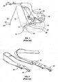
- FIG. 1 shows a prior art child restraint system in accordance with the LATCH system.
- the vehicle (not shown) includes a pair of attachment points or lower anchors 10 located at the bight 12, i.e., between the vehicle's seat cushion 14 and the vehicle's seat back 16.
- FIG. 1 is a side view, only one of the pair of lower anchors 10 is shown. However, the lower anchors 10 are spaced apart so as to be aligned on either side of a child restraint seat 18.
- the vehicle further includes a tether anchor 20 located at the rear shelf or, as shown in phantom lines, at the vehicle floor behind the vehicle seat.
- the child restraint system includes atop tether strap 22 having a hook 24 for fastening to the tether anchor 20.
- the child restraint seat includes a pair of attachments or fasteners 26 extending from either side of the child restraint seat via webbing 28.
- Each fastener is coupled by the user to the lower anchor.
- the lower anchor may be a rigid, round rod or bar, typically six millimeters in diameter.
- each fastener includes a strap (of webbing or some other material) having one end coupled to the fastener and the other end coupled to a point 30 at a respective side of the child restraint seat.
- One or both sides of the child restraint seat may include a webbing adjuster 32 in the webbing.
- the child restraint seat also includes a through hole 34 which extends through the back structure of the child restraint seat.
- FIG. 2 discloses a single webbing belt 40 having a web adjuster 42 and a fastener 44 at each end of the webbing belt.
- the belt of FIG. 2 may be used in the alternative to the lower anchor webbing shown in FIG. 1 or current vehicle seat belt systems.
- the belt of ' FIG. 2 may extend through the through hole 34 of the child restraint seat, with each fastener 44 being secured to a respective lower anchor.
- the belt of FIG. 2 is useful in older child restraint seats which were not designed particularly for a LATCH system.
- the webbing in either FIG. 1 or FIG. 2 could be replaced with another material.
- FIG. 3 is a perspective view of a fastener 50 in accordance with one embodiment of the present invention, in an opened or unlatched position.
- the fastener includes two components, i.e., a clip 52 and a cover 54.
- FIG. 4 shows a top plan view of the clip 52 of FIG. 3
- FIG. 5 shows a top plan view of the cover 54 of FIG. 3.
- the cover 54 includes a main body portion 56, which generally extends along the top of the cover.
- the cover 54 further includes a first wall or flange 58 and a second wall or flange 60 extending downwardly from the main body portion 56 and in an opposing and spaced relationship with one another.
- Each flange 58, 60 includes a notch 62 defining a forward flange portion 64 and a rearward flange portion 66.
- a support rib 68 extends between the first and second flanges 58, 60.
- the main body portion 56 of the cover includes a first opening 70, second opening 72 and a third opening or window 74.
- a handle portion 76 At one end of the cover is a handle portion 76 which tapers outwardly to assist grasping by the user and to provide greater user comfort.
- the cover also includes a pair of tabs 78 extending towards one another from the respective flange 58, 60.
- the clip 52 includes a main stem portion 80 having a wide portion 82 and first and second narrow portions 84, 86.
- the wide portion 82 and the first narrow portion 84 are separated by a pair of slots 88.
- a locking recess 90 and an indicia or marking 92 are located on the stem portion.
- the marking 92 may be, for example, a latch symbol, sticker or phosphorescence dot.
- a webbing attachment which includes a webbing loop 96.
- a hook end 98 is a side view of the fastener 50 of Fig.
- FIG. 6 shows the hook end 98 which can be seen to include a curved portion 100 which defines a hook 102 and a hook opening 104.
- the hook includes a tip 106 having an upper chamfer 108 and a lower chamfer 110.
- FIG. 6 also shows the curved transition portion 112 of the cover.
- FIG. 6 also shows the detent 114 in the cover 54 which is received by the recess 90 in the clip 52.
- the detent 114 could be located on the clip 52 and the recess 90 located on the cover 54.
- FIG. 7 shows a bottom plan view of the fastener 50 of FIG. 3.
- the cover 54 can be seen to include a pair of studs 116 on either side of the second narrow portion 86 of the clip 52.
- the studs 116 could of course be implemented in another manner, such as an abutment.
- FIG. 7 also shows the dome-shaped recess 90 which extends outwardly from FIG. 7 and away from the cover 54.
- FIG. 8 is a perspective view of the fastener 50 of FIG. 3, but in the closed or latched position. It cam be seen that the webbing loop 96 extends farther from the cover 54.
- FIG. 9 is a top plan view of the fastener in the closed or latched position, and wherein the marking 92 appears through the window 74.
- FIG. 10 shows a side view of the fastener in the closed or latched position.
- FIG. 11 shows a bottom plan view of the fastener in the closed or latched position.
- FIG. 12 shows a partial cross-sectional side view of the cover 54, with the clip 52 shown. during the assembly process. It can be seen that the hook end 98 is slid over the support rib 68, with the webbing loop 96 extending away from the cover 54 in a direction opposite from the assembled configuration. The clip 52 is then rotated counterclockwise with respect to FIG. 12, wherein the hook end 98 clears the main body portion 56 of the cover 54 by means of the first opening 70. The clip 52 is rotated further so that the stem portion 80 engages the main body, portion 56, with the stem portion 80 extending between the main body 56 portion and the tabs 78.
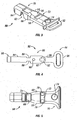
- FIG. 13 is a perspective view of a fastener 50' in accordance with the second embodiment of the present invention.
- the fastener of FIG. 13 is shown in a closed or latched position.
- the fastener of FIG. 13 is substantially similar to the fastener of FIG. 3. Similar features of the fastener of FIG. 13 are shown with the same reference numeral as those used for the fastener of FIG. 3 but with the notation of a prime mark.
- the fastener does not include a window 74. Rather, the marking 92' extends beyond the cover 54' in the closed or latched position, so that the latch symbol 92' is exposed.
- FIG. 14 is a perspective view from beneath the fastener of FIG. 13 and shows the fastener 50' in the closed or latched position.
- the fastener includes a flange shaft 120 extending from the clip 52'.
- a spring 124 is shown and includes one end secured to the flange 120 and another end which is in abutment with the support rib 68' (FIGS. 15, 16). Alternatively, the ends of the spring 124 may be secured to the cover 54' by another securing method such as is common in the art.
- the spring 124 urges the fastener in the closed or latched position, and may be used as a retaining means either alternatively or in addition to the detent/recess of the fastener of FIG. 3. It should be apparent that the recess/detent would be implemented in any one of a variety of configurations as known in the art.
- FIG. 15 shows that the rearward flange portion 66' on each side of the fastener 50', extends downwardly farther than the corresponding forward flange portions 64'. This additional material extending downwardly provides a stop 126, to assist in the installation of the fastener.
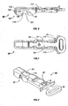
- FIG. 17 is a perspective view of the fastener 50" in accordance with a third embodiment of the present invention, and is shown in the opened or unlatched position.
- FIG. 18 is a side view of the fastener 50".
- FIGS 19 and 20 are top and bottom views, respectively.
- the fastener is similar in some respects as to the previously described fasteners. To the extent the features are similar, the same reference numerals are used but with a double-prime notation.
- the fastener 50" of FIG. 18 includes a clip 52" having an attachment end 94", a stem portion 80", and a hook end 98".
- the hook end includes a curved portion 100" which defines a hook 102" and a hook opening 104".
- a cover 54" is shown to include a main body portion 56" extending along the clip.
- a flange 58" extends downward from the main body portion on one side of the clip.
- the flange includes a notch 62" which defines a forward and rearward flange portion 64", 66".
- the rearward flange portion includes a hook receiving recess 122 and a stop 126".
- a roller 130 is rotatably secured to the rearward flange portion and is spaced in relation to the main body portion 56".
- the stem portion 80" extends along the flange and between the main body portion and the roller. Thus, the roller 130 allows the relative sliding action between the clip 52" and cover 54" and also secures the clip and cover together.
- the attachment end 94" is shown to be coupled to the webbing or strap 134.
- FIG. 21 shows the fastener 50" of FIG. 1.7 but in a closed or latched position. It can be seen that the hook and hook receiving recess 122 close off the hook opening 104".
- FIG. 22 shows a fastener 50" similar to that of FIG. 17, but with a webbing or strap adjuster 132 coupled between the fastener 50" and the strap 134.
- FIG. 23 is a top view of the fastener 50" of FIG. 22.
- FIG. 23 shows the adjuster 132 pivotally coupled to the clip 52" via a hinge or pin 136. It can be seen from FIGS. 22, 23 that the webbing or strap is generally aligned in the same plane as the fastener 50". In the embodiment of FIGS. 22, 23, the fastener 50" will avoid an essentially 90° twist of the webbing 134 at the point of the fastener.
- FIG. 24 shows an alternative means for retaining the fastener in either the locked or unlocked position.
- the clip 52 includes two aligned recesses 150 on the edge of the clip 52.
- the flange of the cover includes a pair of opposing detents 152 which are shown to be received by the respective recess 150.
- the recesses ' 150 and the detents 152 retain the fastener in an open position.
- the clip 52 may be urged towards the open or unlocked position until the recesses 150 receive a pair of opposed and facing detents 154, upon which the detents 154 will retain the fastener in the locked position.
- sufficient force must be exerted so as to overcome the retaining or locking engagement of the detent and recess.
- FIG. 25 shows a fastener in accordance with a fourth embodiment of the present invention, and is shown in the closed or locked position.
- the fastener is similar in respects to the previously described fasteners. To the extent the features are similar, the same reference numerals are used but with a triple-prime notation.
- FIG. 26 is an exploded view of the fastener 50"' of FIG. 25.
- FIG. 26 shows that the cover includes an upper portion 160 and a lower portion 162.
- FIG. 27 is a side view, partial phantom view, of fastener of FIG. 25 and
- FIG. 28 is a bottom view of the fastener of FIG. 25.
- FIG. 25 shows that the fastener 50"' includes latch symbol 164 on the cover, as well as a marking 92 on the clip. With the fastener in the position where there are matching latch symbol 164 and marking 92, the fastener will be shown to be in a closed or latched position. As shown in FIG. 28, the lower portion 162 includes a recess 166 which receives the clip of the hook when the fastener is in the closed or latched position.
- FIG. 29 shows an exploded view similar to that shown in FIG. 26 but as viewed from beneath.
- FIG. 30 shows an alternative arrangement for retaining the clip 52 within the cover.
- the flange of the fastener is shown to include a recessed opening 170 on either side for receiving a pin or rivet 172.
- the clip 52 extends between the main body portion 56 of the cover and the rivet 172. The rivet will be received by the recessed opening 170 in an interference fit, or the remote end of the rivet will be deformed so as to retain the rivet 172 in the cover.
- FIG. 31 shows an optional notch arrangement having a necking feature at 180.
- the necking feature allows the fastener to be slipped over a lower anchor or bar in a snap fit arrangement.
- FIGS. 32 and 33 show an optional feature to assist in the removal of the fastener from a lower anchor.
- the lower anchor is shown at 190.
- the cover of the fastener includes a domed recess 192 which retains a spring 194.
- the fastener is held over the lower anchor 190 in the unlatched position such as shown in FIG. 32.
- the fastener is then pressed downwardly upon the lower anchor 190 against the force of the spring 194 until the lower anchor 190 is received by the hook, whereupon the fastener is positioned into the locked arrangement such as shown in FIG: 33.
- the fastener is positioned in the unlatched position and the spring 194 will assist in removing the fastener from the lower anchor 190 such as shown in FIG. 32.
- the cover may be made of any suitable material such as plastic, aluminum, zinc die cast, a specialized rubber or a composite.
- the fastener of the present invention may be coupled to a strap or webbing of a child restraint seat, for example.
- the user is able to set the fastener in the opened or unlatched position and easily slide the fastener into the bight 12 in the area of the lower anchor 10.
- the lower anchor 10 is difficult to view.
- the stop is intended to come into contact with the lower anchor 10, thereby indicating to the user that the notch is aligned over the lower anchor. Further insertion pressure if necessary, will slide the clip, relative to the cover, and assure that the fastener is in the open position.
- the user is then able to apply a downward pressure on the fastener so that the notch receives the lower anchor 10.
- the fastener may be urged downward to receive the lower anchor 10.
- the widened area of the notch guides the fastener over the lower anchor 10, even if the fastener is not perfectly aligned perpendicular to the lower anchor 10.
- the user Upon the fastener being placed over the lower anchor, the user is able to maintain a downward pressure on the fastener, while pulling on the webbing to move the fastener into the closed or latched position.
- the two studs provide a stop for the clip in both the open and closed positions, such as demonstrated by FIGS. 7 and 11, respectively.
- the flange and the support rib close-off the hook opening and retain the lower anchor within the hook.
- the upper and lower chamfer will help guide the tip of the hook off the lower anchor and either move the fastener out of engagement with the lower anchor or into engagement with the lower anchor.
- the curved transition portion prevents a false latch indication.
- the fastener will move to the closed or latched position and the marking will be exposed, either via the opening or in the area beyond the cover.
- the fastener will remain in the latched or closed position by means of either the detent recess combination or the spring arrangement, or a combination of both, or some other similar lock arrangement.
- the user is now able to adjust one or more adjustment devices to provide tension in the strap or webbing.
- the tension will serve to assist in maintaining the fastener in the locked or closed position.
- the user introduces slack in the strap, and then grasps the fastener and slides it into the unlatched position.
- the fastener may then be removed from the lower anchor by rotating or twisting the fastener 90° and extracting the fastener from the seat bight.
Landscapes
- Seats For Vehicles (AREA)
Applications Claiming Priority (2)
| Application Number | Priority Date | Filing Date | Title |
|---|---|---|---|
| US384884 | 2003-03-10 | ||
| US10/384,884 US20040195900A1 (en) | 2003-03-10 | 2003-03-10 | Fastener with sliding hook for restraint system, and method of using fastener |
Publications (2)
| Publication Number | Publication Date |
|---|---|
| EP1459641A2 true EP1459641A2 (fr) | 2004-09-22 |
| EP1459641A3 EP1459641A3 (fr) | 2007-01-10 |
Family
ID=32824815
Family Applications (1)
| Application Number | Title | Priority Date | Filing Date |
|---|---|---|---|
| EP04290565A Withdrawn EP1459641A3 (fr) | 2003-03-10 | 2004-03-02 | Attache à crochet coulissant pour système de retenue, et méthode pour l'utilisation d'une telle attache |
Country Status (2)
| Country | Link |
|---|---|
| US (1) | US20040195900A1 (fr) |
| EP (1) | EP1459641A3 (fr) |
Cited By (2)
| Publication number | Priority date | Publication date | Assignee | Title |
|---|---|---|---|---|
| WO2014089619A1 (fr) * | 2012-12-11 | 2014-06-19 | Infa-Secure Pty Ltd | Dispositif d'ancrage |
| US12330585B1 (en) * | 2024-07-12 | 2025-06-17 | Taiwan Racing Products Co., Ltd. | Seat belt anchor |
Families Citing this family (15)
| Publication number | Priority date | Publication date | Assignee | Title |
|---|---|---|---|---|
| US7195302B2 (en) * | 2005-08-22 | 2007-03-27 | Nissan Technical Center North America, Inc. | Vehicle rear seating arrangement |
| US7467604B1 (en) * | 2005-09-15 | 2008-12-23 | Swing River, Llc | Hands free dog leash which enables the dog to move side to side through a pulley attachment and which includes anti-tangling swivel mechanisms and safety mechanisms |
| US7918001B2 (en) * | 2008-03-31 | 2011-04-05 | Amsafe Commercial Products, Inc. | Multi-pivot latch assemblies |
| US8713765B2 (en) | 2008-03-31 | 2014-05-06 | Amsafe Commercial Products, Inc. | Multi-pivot latch assemblies |
| US8646158B2 (en) * | 2008-03-31 | 2014-02-11 | Amsafe Commercial Products, Inc. | Multi-pivot latch assemblies |
| US8291555B2 (en) * | 2008-03-31 | 2012-10-23 | Amsafe Commercial Products, Inc. | Multi-pivot latch assemblies |
| DE102010045296B4 (de) | 2010-09-14 | 2019-02-21 | Sortimo International Gmbh | Rahmenkonstruktion für ein Transportfahrzeug mit mindestens einer Profilschiene und Vorrichtung zur lösbaren Befestigung eines Haltegurts an der Profilschiene |
| USD649433S1 (en) | 2011-02-09 | 2011-11-29 | Amsafe Commercial Products, Inc. | Latch assembly |
| USD649432S1 (en) | 2011-02-09 | 2011-11-29 | Amsafe Commercial Products, Inc. | Latch assembly |
| US9022483B2 (en) | 2012-06-07 | 2015-05-05 | Shield Restraint Systems, Inc. | Seatbelt buckle tongue assembly |
| US9718427B2 (en) | 2013-07-19 | 2017-08-01 | Shield Restraint Sytems, Inc. | Latch device and anchor with swivel coupling |
| US9358914B2 (en) | 2014-06-05 | 2016-06-07 | Amsafe, Inc. | Seatbelt anchor systems for aircraft and other vehicles, and associated methods of manufacture and use |
| MX2022014280A (es) * | 2020-05-14 | 2023-01-18 | Mrm Hk Ltd | Sujetador. |
| WO2022204693A1 (fr) * | 2021-03-23 | 2022-09-29 | Indiana Mills & Manufacturing, Inc. | Mousqueton à insert de pince |
| IT202300004497U1 (it) * | 2023-11-02 | 2025-05-02 | Crispi Sport S R L | Struttura di ghetta rimovibile di protezione per calzature. |
Family Cites Families (22)
| Publication number | Priority date | Publication date | Assignee | Title |
|---|---|---|---|---|
| GB1047761A (fr) * | 1900-01-01 | |||
| US373535A (en) * | 1887-11-22 | Snap-hook | ||
| US1130613A (en) * | 1914-01-21 | 1915-03-02 | Edward G Hilliard | Chain-hook. |
| US1200318A (en) * | 1916-03-24 | 1916-10-03 | Archie C Cummins | Chain-connector. |
| US1240381A (en) * | 1916-05-17 | 1917-09-18 | Willard L Smith | Snap-hook. |
| US1239993A (en) * | 1917-04-28 | 1917-09-11 | Frank L West | Connecting and retaining device. |
| US1246911A (en) * | 1917-06-09 | 1917-11-20 | B A Ballou & Company Inc | Chain-connector. |
| US2010277A (en) * | 1934-10-01 | 1935-08-06 | Willard L Smith | Safety snap hook |
| US2603524A (en) * | 1948-12-01 | 1952-07-15 | Alexander F Amelung | Hook having releasable safety locking means |
| US2821001A (en) * | 1953-12-10 | 1958-01-28 | Du Pont | Clamp |
| US2952290A (en) * | 1958-04-01 | 1960-09-13 | Martin S Gaspardo | Tire chain |
| NL260638A (fr) * | 1960-02-01 | |||
| US3212153A (en) * | 1963-12-13 | 1965-10-19 | Michael J Lynch | Snaphooks |
| US3271510A (en) * | 1964-12-01 | 1966-09-06 | Robert M Decker | Remotely applied conductor spacer |
| US3714684A (en) * | 1969-06-12 | 1973-02-06 | Chainbelt Inc R | Ski safety strap latch |
| USRE27986E (en) * | 1973-05-29 | 1974-04-23 | Cable strain relief device | |
| US3984900A (en) * | 1975-08-29 | 1976-10-12 | James R. Johnston | Coupling device |
| GB1532909A (en) * | 1977-04-22 | 1978-11-22 | Cagnato E | Safety fastener |
| CH629944A5 (fr) * | 1979-08-10 | 1982-05-28 | Attilio Brentini | Dispositif de fermeture. |
| FR2531322B1 (fr) * | 1982-08-03 | 1986-10-03 | Leroux Jacques | Fermoir pour chaine de collier |
| US6408493B1 (en) * | 2000-06-22 | 2002-06-25 | Yurman Design Inc. | Jewelry clasp |
| AUPQ845100A0 (en) * | 2000-06-30 | 2000-07-27 | Britax Child-Care Products Pty Ltd | Attachment of child shoulder harness to a booster seat |
-
2003
- 2003-03-10 US US10/384,884 patent/US20040195900A1/en not_active Abandoned
-
2004
- 2004-03-02 EP EP04290565A patent/EP1459641A3/fr not_active Withdrawn
Cited By (3)
| Publication number | Priority date | Publication date | Assignee | Title |
|---|---|---|---|---|
| WO2014089619A1 (fr) * | 2012-12-11 | 2014-06-19 | Infa-Secure Pty Ltd | Dispositif d'ancrage |
| AU2013360020B2 (en) * | 2012-12-11 | 2017-11-02 | Hbg Ip Holding Pty Limited | An anchorage device |
| US12330585B1 (en) * | 2024-07-12 | 2025-06-17 | Taiwan Racing Products Co., Ltd. | Seat belt anchor |
Also Published As
| Publication number | Publication date |
|---|---|
| EP1459641A3 (fr) | 2007-01-10 |
| US20040195900A1 (en) | 2004-10-07 |
Similar Documents
| Publication | Publication Date | Title |
|---|---|---|
| US7404239B1 (en) | Adjuster for adjustable restraint strap | |
| EP1459641A2 (fr) | Attache à crochet coulissant pour système de retenue, et méthode pour l'utilisation d'une telle attache | |
| US7278684B2 (en) | Retractable coupling apparatus | |
| US8444222B2 (en) | Child safety seat attachment belt retractor system | |
| CN209955940U (zh) | 座椅安全带连接器舌片组件和座椅安全带组件 | |
| US5902015A (en) | Seat belt gripping tool, and method of use | |
| US8827364B2 (en) | Child carrier restraint system | |
| JP2002079859A (ja) | 補助シートへの子供用ショルダ・ハーネスの取付け具 | |
| US8136841B2 (en) | Shoulder position adjuster device | |
| US8240761B2 (en) | Lower anchor coupling | |
| US6623037B2 (en) | Seat belt configuration having individual belt retractors for the shoulder belt and the lap belt | |
| CN102848941A (zh) | 儿童座椅 | |
| US7073235B2 (en) | Non-inertial release safety restraint belt buckle systems | |
| WO1998038061A1 (fr) | Dispositif de montage pour siege-auto d'enfant | |
| US7716795B2 (en) | Anti-rattle tongue plate assembly | |
| US4840404A (en) | Seat belt system having shoulder height support | |
| CN102099228A (zh) | 安全带锚定装置 | |
| US5000481A (en) | Locking device for vehicle seat belts | |
| US5106121A (en) | Occupant restraint belt anchorage arrangement | |
| GB2167798A (en) | Boot lid fastening device for motor vehicles | |
| JPH05211908A (ja) | 乗物用安全装置及び安全装置用のタング・アセンブリ | |
| CN101670822B (zh) | 车辆用安全带装置 | |
| US20080290717A1 (en) | Seatbelt pulling tool | |
| JP2002012069A (ja) | 子供用車両シートを固定物に固定するつなぎ止めラッチ | |
| GB2365916A (en) | Hook and tether strap length adjuster |
Legal Events
| Date | Code | Title | Description |
|---|---|---|---|
| PUAI | Public reference made under article 153(3) epc to a published international application that has entered the european phase |
Free format text: ORIGINAL CODE: 0009012 |
|
| AK | Designated contracting states |
Kind code of ref document: A2 Designated state(s): AT BE BG CH CY CZ DE DK EE ES FI FR GB GR HU IE IT LI LU MC NL PL PT RO SE SI SK TR |
|
| AX | Request for extension of the european patent |
Extension state: AL HR LT LV MK |
|
| PUAL | Search report despatched |
Free format text: ORIGINAL CODE: 0009013 |
|
| AK | Designated contracting states |
Kind code of ref document: A3 Designated state(s): AT BE BG CH CY CZ DE DK EE ES FI FR GB GR HU IE IT LI LU MC NL PL PT RO SE SI SK TR |
|
| AX | Request for extension of the european patent |
Extension state: AL LT LV MK |
|
| 17P | Request for examination filed |
Effective date: 20070620 |
|
| AKX | Designation fees paid |
Designated state(s): AT BE BG CH CY CZ DE DK EE ES FI FR GB GR HU IE IT LI LU MC NL PL PT RO SE SI SK TR |
|
| STAA | Information on the status of an ep patent application or granted ep patent |
Free format text: STATUS: THE APPLICATION IS DEEMED TO BE WITHDRAWN |
|
| 18D | Application deemed to be withdrawn |
Effective date: 20081001 |