EP1459651A2 - Paroi superieure d'un tiroir compose de plusieurs elements individuels - Google Patents
Paroi superieure d'un tiroir compose de plusieurs elements individuels Download PDFInfo
- Publication number
- EP1459651A2 EP1459651A2 EP04004924A EP04004924A EP1459651A2 EP 1459651 A2 EP1459651 A2 EP 1459651A2 EP 04004924 A EP04004924 A EP 04004924A EP 04004924 A EP04004924 A EP 04004924A EP 1459651 A2 EP1459651 A2 EP 1459651A2
- Authority
- EP
- European Patent Office
- Prior art keywords
- attachment
- rear wall
- front panel
- side frames
- corner pieces
- Prior art date
- Legal status (The legal status is an assumption and is not a legal conclusion. Google has not performed a legal analysis and makes no representation as to the accuracy of the status listed.)
- Withdrawn
Links
- 230000000284 resting effect Effects 0.000 claims description 5
- 230000006978 adaptation Effects 0.000 description 2
- 238000010276 construction Methods 0.000 description 2
- 230000001419 dependent effect Effects 0.000 description 1
Images





Classifications
-
- A—HUMAN NECESSITIES
- A47—FURNITURE; DOMESTIC ARTICLES OR APPLIANCES; COFFEE MILLS; SPICE MILLS; SUCTION CLEANERS IN GENERAL
- A47B—TABLES; DESKS; OFFICE FURNITURE; CABINETS; DRAWERS; GENERAL DETAILS OF FURNITURE
- A47B88/00—Drawers for tables, cabinets or like furniture; Guides for drawers
- A47B88/90—Constructional details of drawers
-
- A—HUMAN NECESSITIES
- A47—FURNITURE; DOMESTIC ARTICLES OR APPLIANCES; COFFEE MILLS; SPICE MILLS; SUCTION CLEANERS IN GENERAL
- A47B—TABLES; DESKS; OFFICE FURNITURE; CABINETS; DRAWERS; GENERAL DETAILS OF FURNITURE
- A47B88/00—Drawers for tables, cabinets or like furniture; Guides for drawers
- A47B88/90—Constructional details of drawers
- A47B88/941—Drawers being constructed from two or more parts
-
- A—HUMAN NECESSITIES
- A47—FURNITURE; DOMESTIC ARTICLES OR APPLIANCES; COFFEE MILLS; SPICE MILLS; SUCTION CLEANERS IN GENERAL
- A47B—TABLES; DESKS; OFFICE FURNITURE; CABINETS; DRAWERS; GENERAL DETAILS OF FURNITURE
- A47B2210/00—General construction of drawers, guides and guide devices
- A47B2210/02—Drawers with hollow lateral walls in two parts
-
- A—HUMAN NECESSITIES
- A47—FURNITURE; DOMESTIC ARTICLES OR APPLIANCES; COFFEE MILLS; SPICE MILLS; SUCTION CLEANERS IN GENERAL
- A47B—TABLES; DESKS; OFFICE FURNITURE; CABINETS; DRAWERS; GENERAL DETAILS OF FURNITURE
- A47B88/00—Drawers for tables, cabinets or like furniture; Guides for drawers
- A47B88/90—Constructional details of drawers
- A47B88/919—Accessories or additional elements for drawers, e.g. drawer lighting
- A47B88/925—Additional side walls mountable on existing side walls
Definitions
- the present invention relates to an attachment consisting of several individual parts of a drawer equipped with two side frames, a rear wall and a front panel for increasing its receiving volume, the attachment overall being able to be positively and / or non-positively placed on the side frames and the rear panel and on the front panel is definable.
- the present invention has for its object to design an attachment of a drawer of the generic type so that it can be easily and safely installed and in particular can be easily adapted to different drawer sizes.
- the individual components of the attachment comprise two L-shaped corner pieces each made in one piece and at least one plate-shaped intermediate piece, the two legs of the corner pieces resting on the one hand on the side frames and on the other hand on the rear wall and in that at least one intermediate piece rests between the mutually facing and spaced end faces of the ends of the legs of the corner pieces resting on the rear wall.
- the one-piece L-shaped corner pieces can be easily and securely placed on the side frames and the adjoining corner areas of the rear wall and fixed there, ensuring high stability for the entire attachment.
- the at least one intermediate piece which is placed on the rear wall, enables the attachment to be adapted to different drawer widths, since only a corresponding length of the intermediate piece has to be selected here in order to be able to adapt the attachment to different widths of a drawer.
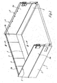
- the reference numeral 1 denotes a drawer (shown without a front panel), which has two side frames 2, a rear wall 3 and the front panel already mentioned, but not shown for reasons of clarity and opposite the rear wall 3.
- the attachment 4 essentially consists of two one-piece, L-shaped corner pieces 5 and two intermediate pieces 6 and 7.
- the L-shaped corner pieces 5 each rest with one of their legs 5a on the side frames 2 and with their other legs 5b on the rear wall 3.
- the one-piece corner pieces 5 result in a high overall stability of the complete attachment 4, in addition, the assembly of the attachment 4 is considerably facilitated by the one-piece corner pieces 5, since this corner pieces 4 are fixed in terms of the side frames 2 and the rear wall 3, without needing additional connecting means for the corresponding legs 5a and 5b in the corner area.
- the entire attachment 4 can be adapted in a simple manner to different drawer widths, since only the length of the intermediate piece or pieces is to be adapted accordingly.
- Intermediate pieces can also be used in the area of the legs 5a of the corner pieces 5 resting on the side frames 2, in order to also enable adaptation to different depths of drawers.
- the individual components of the attachment 4 are positively and / or non-positively connected to the side frames 2 and the rear wall 3 of the drawer 1 in the assembled state, for example by locking lugs 8, which, as shown by way of example in FIG. 4, on the legs 5a and 5b and are integrally formed on the intermediate pieces 6 and 7 and lock the said components with the side frames 2 and the rear wall 3.
- the legs 5a of the corner pieces 5, which rest on the side frames 2, are adapted in terms of their length to the total length of the side frames 2. This means that the legs 5a extend over the entire length of the side frames 2 up to the fastening plane of a front panel not shown in the drawings and opposite the rear wall 3.
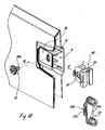
- the legs 5a are equipped in their front end area facing a front panel with a receiving chamber 9 for receiving and holding means for connection to a front panel.
- These means for fastening to a front panel are in detail a holding body 10, an eccentric 11 and a fastening element 12, which represents the direct connecting means to a front panel.
- the holding body 10 is inserted into the receiving chamber 9 in the direction of arrow A in FIG. After the holding body 10 has been introduced into the receiving chamber 9 in its intended position, the eccentric 11 in Direction of arrow B used in Figure 10. An eccentric pin 11a of the eccentric 11 passes through an elongated hole 13 in a side wall 14 of the receiving chamber 9 and engages in a transverse bore 15 in the holding body 10. Thus, the holding body 10 is secured against falling out, especially since the eccentric 11 is held by lugs formed on the holding body 10 in the sense of a clip connection (see FIG. Figure 11).
- the inserted holding body 10 can be adjusted in the sense of the double arrow C in FIG. 10 via this eccentric 11.
- the holding body 10 is fixed in its intended position within the receiving chamber 9 by the aforementioned clip connection.
- the fastening element 12 which is provided with two dowel pins 12a, is fixed to a front panel via these two dowel pins 12a.
- each fastening element 12 is equipped with a T-shaped anchor web 12b which engages in a C-shaped groove 16 of the holding body.
- the transverse web of the T-shaped anchor web is equipped on the back with a toothing or latching 12c, which is assigned a corresponding latching or toothing 16a on the corresponding legs of the C-shaped receiving groove 16.
- This toothing or latching 12c on the one hand and 16a on the other hand allows a front panel on the holding body 10 to be connected in a secure but adjustable manner with respect to the altitude.
- connection of the side legs 5a to a front panel of a drawer 1 gives the possibility of carrying out an adjustment between the components mentioned in all required directions, regardless of an adjustment, which is possible in a known manner, between the front panel on the one hand and the drawer 1 on the other hand.
- the components of the attachment 4 (corner pieces 5, intermediate pieces 6, 7) are open towards their underside and can therefore be easily placed on a drawer.
- the holding body 10 In the assembled state, there is a connection between the holding body 10 and the fastening element 12 in the front panel area, in rear area, a latching between the attachment 4 and the rear wall 3 or the rear areas of the side frames 2 can be produced.
- This simple type of assembly even enables it to be carried out by persons who are technically less experienced, ie an end user can, if appropriate, mount an attachment according to the invention on a drawer.
- the assembly of the attachment described can, for example, be carried out in such a way that the end user assembles an attachment 4 corresponding to the size of the drawer 1 from the end pieces 5 and intermediate pieces 6, 7, by using the end pieces of the intermediate pieces 6, 7 or the L-shaped corner piece 5 attached non-positively or positively acting connecting means assembles a complete attachment 4 and places this on the drawer from above.
- the attachment 4 is then held by the fastening elements 12, on the rear wall 3 by the locking lugs 8.
- the non-positive or form-fitting connecting means attached to the end of the intermediate pieces 6, 7 or at the corner piece 5 can be designed, for example, according to FIG. 7 on the one hand as guide webs and on the other hand as an undercut, so that the parts 6, 7, 5 in the sense of a flat guide by pushing on can be positively connected.
Landscapes
- Drawers Of Furniture (AREA)
- Connection Of Plates (AREA)
Applications Claiming Priority (2)
| Application Number | Priority Date | Filing Date | Title |
|---|---|---|---|
| DE20304159U DE20304159U1 (de) | 2003-03-15 | 2003-03-15 | Aus mehreren Einzelteilen bestehender Aufsatz eines Schubkastens |
| DE20304159U | 2003-03-15 |
Publications (2)
| Publication Number | Publication Date |
|---|---|
| EP1459651A2 true EP1459651A2 (fr) | 2004-09-22 |
| EP1459651A3 EP1459651A3 (fr) | 2005-10-12 |
Family
ID=7980833
Family Applications (1)
| Application Number | Title | Priority Date | Filing Date |
|---|---|---|---|
| EP04004924A Withdrawn EP1459651A3 (fr) | 2003-03-15 | 2004-03-03 | Paroi superieure d'un tiroir compose de plusieurs elements individuels |
Country Status (2)
| Country | Link |
|---|---|
| EP (1) | EP1459651A3 (fr) |
| DE (1) | DE20304159U1 (fr) |
Cited By (4)
| Publication number | Priority date | Publication date | Assignee | Title |
|---|---|---|---|---|
| WO2010054532A1 (fr) * | 2008-11-12 | 2010-05-20 | Tseng Chi-Pin | Armoire à tiroirs apte au changement de tailles d'espace tridimensionnel |
| CN103533862A (zh) * | 2011-05-06 | 2014-01-22 | 保罗海蒂诗有限及两合公司 | 抽屉 |
| US9060605B2 (en) | 2011-07-07 | 2015-06-23 | Julius Blum Gmbh | Drawer |
| CN104287483B (zh) * | 2014-09-27 | 2017-01-18 | 伍志勇 | 一种抽屉加高侧板的快速拆装稳定结构 |
Families Citing this family (5)
| Publication number | Priority date | Publication date | Assignee | Title |
|---|---|---|---|---|
| DE202007010297U1 (de) | 2007-07-20 | 2008-08-21 | Megamat GmbH Büro- und Lagertechnik | Lagergutträger mit Unterteilungsanordnung |
| DE202009013393U1 (de) * | 2009-10-21 | 2011-03-03 | Paul Hettich Gmbh & Co. Kg | Zargenhülle mit mindestens einem Zargenadapter |
| AT515689B1 (de) * | 2014-06-18 | 2015-11-15 | Blum Gmbh Julius | Schublade |
| DE202014105497U1 (de) * | 2014-11-17 | 2016-02-18 | Grass Gmbh | Wandelement, Zarge, Schublade und Möbel |
| GB2604862B (en) * | 2021-03-12 | 2025-05-07 | Dside Design Ltd | Improvements relating to drawers |
Family Cites Families (2)
| Publication number | Priority date | Publication date | Assignee | Title |
|---|---|---|---|---|
| US4723679A (en) * | 1986-02-28 | 1988-02-09 | Sinchok John D | Tray or tote box collar extension |
| US5281020A (en) * | 1991-10-21 | 1994-01-25 | Romick Jerome M | Stackable drawer system |
-
2003
- 2003-03-15 DE DE20304159U patent/DE20304159U1/de not_active Expired - Lifetime
-
2004
- 2004-03-03 EP EP04004924A patent/EP1459651A3/fr not_active Withdrawn
Cited By (5)
| Publication number | Priority date | Publication date | Assignee | Title |
|---|---|---|---|---|
| WO2010054532A1 (fr) * | 2008-11-12 | 2010-05-20 | Tseng Chi-Pin | Armoire à tiroirs apte au changement de tailles d'espace tridimensionnel |
| CN103533862A (zh) * | 2011-05-06 | 2014-01-22 | 保罗海蒂诗有限及两合公司 | 抽屉 |
| CN103533862B (zh) * | 2011-05-06 | 2015-11-25 | 保罗海蒂诗有限及两合公司 | 抽屉 |
| US9060605B2 (en) | 2011-07-07 | 2015-06-23 | Julius Blum Gmbh | Drawer |
| CN104287483B (zh) * | 2014-09-27 | 2017-01-18 | 伍志勇 | 一种抽屉加高侧板的快速拆装稳定结构 |
Also Published As
| Publication number | Publication date |
|---|---|
| DE20304159U1 (de) | 2003-05-28 |
| EP1459651A3 (fr) | 2005-10-12 |
Similar Documents
| Publication | Publication Date | Title |
|---|---|---|
| EP2059145B1 (fr) | Tiroir | |
| DE2633972A1 (de) | Verbindungsanordnung fuer moebel | |
| EP3496572B1 (fr) | Dispositif de fixation d'un objet de préférence plat sur une construction | |
| EP2704604B1 (fr) | Tiroir | |
| EP1916361A1 (fr) | Poignée prevue pour être montée dans une ouverture | |
| EP2606766A1 (fr) | Guidage d'extraction pour tiroirs coulissants avec crochet de préhension | |
| DE8307469U1 (de) | Schubkasten aus kunststoff fuer moebel | |
| DE20304159U1 (de) | Aus mehreren Einzelteilen bestehender Aufsatz eines Schubkastens | |
| DE3607754C2 (de) | Wandbefestigungselement für Flächen- und Kompaktheizkörper | |
| DE2923903C2 (fr) | ||
| EP0340285A1 (fr) | Tiroir a deux chassis lateraux, de preference metalliques | |
| DE19712278A1 (de) | Bodenelement | |
| DE9007404U1 (de) | Halterungsbeschlag für Schubladen-Ausziehführungen | |
| EP0291973B1 (fr) | Pièce de jonction de deux barres profilées aboutissant angulairement pour cadres de fenêtre ou porte | |
| DE202013100898U1 (de) | Konstruktionseinheit, insbesondere für Möbel | |
| DE102016104889B4 (de) | Eckverbinder | |
| EP1445409B1 (fr) | Elément de support et réception pour charnières | |
| DE202008006071U1 (de) | Leichtbauplatte zur Verwendung als Möbelplatte | |
| DE20219174U1 (de) | Dichtung insbesondere selbsttätig absenkende Bodendichtung für Türen | |
| AT507990A1 (de) | Verbindungsteil und verbindungsanordnungen zur fluchtenden verbindung benachbarter doppelstab- oder flachstab- oder kombinierter doppelstab- flachstab-gittermatten und damit gebauter zaun | |
| EP3017719B1 (fr) | Composant lateral, tiroir et meuble | |
| EP0972904B1 (fr) | Cadre pour porte de meuble avec élément de ferrure encliquetable | |
| DE19734647A1 (de) | Beschlagteil an einem Flügel oder einem festen Rahmen eines Fensters, einer Tür od. dgl. | |
| DE8812055U1 (de) | Scharnierstift | |
| DE2250797A1 (de) | Scharnier fuer ein fenster, eine tuer od. dgl |
Legal Events
| Date | Code | Title | Description |
|---|---|---|---|
| PUAI | Public reference made under article 153(3) epc to a published international application that has entered the european phase |
Free format text: ORIGINAL CODE: 0009012 |
|
| AK | Designated contracting states |
Kind code of ref document: A2 Designated state(s): AT BE BG CH CY CZ DE DK EE ES FI FR GB GR HU IE IT LI LU MC NL PL PT RO SE SI SK TR |
|
| AX | Request for extension of the european patent |
Extension state: AL LT LV MK |
|
| PUAL | Search report despatched |
Free format text: ORIGINAL CODE: 0009013 |
|
| AK | Designated contracting states |
Kind code of ref document: A3 Designated state(s): AT BE BG CH CY CZ DE DK EE ES FI FR GB GR HU IE IT LI LU MC NL PL PT RO SE SI SK TR |
|
| AX | Request for extension of the european patent |
Extension state: AL LT LV MK |
|
| 17P | Request for examination filed |
Effective date: 20060330 |
|
| AKX | Designation fees paid |
Designated state(s): AT BE BG CH CY CZ DE DK EE ES FI FR GB GR HU IE IT LI LU MC NL PL PT RO SE SI SK TR |
|
| 17Q | First examination report despatched |
Effective date: 20071108 |
|
| STAA | Information on the status of an ep patent application or granted ep patent |
Free format text: STATUS: THE APPLICATION IS DEEMED TO BE WITHDRAWN |
|
| 18D | Application deemed to be withdrawn |
Effective date: 20141001 |