EP1459652A2 - Glissière pour un tiroir - Google Patents
Glissière pour un tiroir Download PDFInfo
- Publication number
- EP1459652A2 EP1459652A2 EP04102962A EP04102962A EP1459652A2 EP 1459652 A2 EP1459652 A2 EP 1459652A2 EP 04102962 A EP04102962 A EP 04102962A EP 04102962 A EP04102962 A EP 04102962A EP 1459652 A2 EP1459652 A2 EP 1459652A2
- Authority
- EP
- European Patent Office
- Prior art keywords
- pull
- drawer
- end piece
- slide
- horizontal
- Prior art date
- Legal status (The legal status is an assumption and is not a legal conclusion. Google has not performed a legal analysis and makes no representation as to the accuracy of the status listed.)
- Withdrawn
Links
Images


Classifications
-
- A—HUMAN NECESSITIES
- A47—FURNITURE; DOMESTIC ARTICLES OR APPLIANCES; COFFEE MILLS; SPICE MILLS; SUCTION CLEANERS IN GENERAL
- A47B—TABLES; DESKS; OFFICE FURNITURE; CABINETS; DRAWERS; GENERAL DETAILS OF FURNITURE
- A47B88/00—Drawers for tables, cabinets or like furniture; Guides for drawers
- A47B88/40—Sliding drawers; Slides or guides therefor
- A47B88/453—Actuated drawers
- A47B88/46—Actuated drawers operated by mechanically-stored energy, e.g. by springs
- A47B88/467—Actuated drawers operated by mechanically-stored energy, e.g. by springs self-closing
-
- A—HUMAN NECESSITIES
- A47—FURNITURE; DOMESTIC ARTICLES OR APPLIANCES; COFFEE MILLS; SPICE MILLS; SUCTION CLEANERS IN GENERAL
- A47B—TABLES; DESKS; OFFICE FURNITURE; CABINETS; DRAWERS; GENERAL DETAILS OF FURNITURE
- A47B88/00—Drawers for tables, cabinets or like furniture; Guides for drawers
- A47B88/40—Sliding drawers; Slides or guides therefor
- A47B88/423—Fastening devices for slides or guides
- A47B88/427—Fastening devices for slides or guides at drawer side
-
- A—HUMAN NECESSITIES
- A47—FURNITURE; DOMESTIC ARTICLES OR APPLIANCES; COFFEE MILLS; SPICE MILLS; SUCTION CLEANERS IN GENERAL
- A47B—TABLES; DESKS; OFFICE FURNITURE; CABINETS; DRAWERS; GENERAL DETAILS OF FURNITURE
- A47B88/00—Drawers for tables, cabinets or like furniture; Guides for drawers
- A47B88/90—Constructional details of drawers
- A47B88/944—Drawers characterised by the front panel
- A47B88/95—Drawers characterised by the front panel characterised by connection means for the front panel
- A47B88/956—Drawers characterised by the front panel characterised by connection means for the front panel for enabling adjustment of the front panel
-
- A—HUMAN NECESSITIES
- A47—FURNITURE; DOMESTIC ARTICLES OR APPLIANCES; COFFEE MILLS; SPICE MILLS; SUCTION CLEANERS IN GENERAL
- A47B—TABLES; DESKS; OFFICE FURNITURE; CABINETS; DRAWERS; GENERAL DETAILS OF FURNITURE
- A47B2210/00—General construction of drawers, guides and guide devices
- A47B2210/0002—Guide construction for drawers
- A47B2210/0029—Guide bearing means
- A47B2210/0043—Wheels
- A47B2210/0045—Wheels whereof only one per slide
-
- A—HUMAN NECESSITIES
- A47—FURNITURE; DOMESTIC ARTICLES OR APPLIANCES; COFFEE MILLS; SPICE MILLS; SUCTION CLEANERS IN GENERAL
- A47B—TABLES; DESKS; OFFICE FURNITURE; CABINETS; DRAWERS; GENERAL DETAILS OF FURNITURE
- A47B2230/00—Furniture jointing; Furniture with such jointing
- A47B2230/0003—Adjustable furniture jointing
- A47B2230/0014—Height or width adjustment using eccenter mechanisms
Definitions
- the invention relates to a pull-out guide for a drawer with two body-side support rails, which support rollers rotatably mounted about horizontal axes, and with two drawer-side pull-out rails, the horizontal catwalks of which are angled from the upper sides of their vertical webs on at least the two in the area of the front of the Support the castors of the mounting rails on the carcass part.
- Such a pull-out guide for a drawer is known for example from EP 0 406 703 A1.
- Drawers are usually parts of furniture that contain several drawers and / or flaps and doors, so that the front side walls or front panels of the drawers must be aligned with one another and possibly with respect to the doors or flaps so that gaps or gaps of equal size are formed between them . Due to unavoidable manufacturing tolerances, it is necessary to adjust the height of the front sides or front panels of the drawers in order to be able to set the desired distances from other furniture parts. Such adjustability is not provided in the pull-out guide for drawers known from EP 0 406 703 A1.
- a pull-out guide for drawers is known in which the front panels of the drawers can be adjusted in height by providing a height-adjustable stop with a run-up surface for the running web of the other rail, which can be adjusted by pivoting the height after adjust.
- the known height-adjustable stop requires a relatively complex design and forms a stop against which the rail abuts with an audible stop.
- the object of the invention is to provide a pull-out guide for a drawer which enables the front panel of the drawer to be adjusted in a simple manner.
- this object is achieved in that the horizontal catwalks are provided at their front end areas with sections which pivot through adjusting devices or move in height to let.
- the pull-out guide according to the invention thus enables a simple adjustment of the height of the front plate of the drawer in that the front end areas of the horizontal walkways can be adjusted in height by adjusting devices.
- each front end region of the horizontal catwalks is cut free from the vertical webs of the pull-out rails and is provided with an adjusting device by means of which the cut end region of each catwalk can be pivoted relative to the vertical web.
- the pull-out guide according to the invention thus enables a simple height adjustment of the front plate of each drawer in that the cut-out section of each pull-out rail is pivoted by the required amount. As a result of this pivoting, the gradient of the horizontal catwalks is changed in a continuous manner without any stops causing undesirable noises.
- the actuating device can consist, for example, of an adjusting screw which is rotatably but non-displaceably connected in the axial direction to the vertical web of the pull-out rail and screwed into a threaded hole in the cut-out part of the horizontal catwalk.
- the actuating device consists of a slide which is displaceable transversely to each pull-out rail and which is provided with a groove which surrounds the end region of the cut-off section of the catwalk and a displacement device.
- the slide is expediently guided between lateral guide webs of a guide piece connected to the pull-out rail and provided with a transverse elongated hole, the sides of which enclose a cylindrical disk which is attached eccentrically to a shaft which is rotatably but axially immovably connected to the guide piece.
- each of the front end regions of the horizontal catwalks is removed by a cut-out and with each of the vertical webs of the pull-out rails a flat housing-like end piece is connected to a lower, obliquely upwardly extending support surface which is adjacent to the support surface of the angled horizontal catwalk continues this, and that in the end piece a slide is guided by an adjusting device so that it can be extended downward beyond the support surface of the end piece and thereby forms a height-adjustable support surface.
- the end piece is expediently provided with a recess corresponding to the contour of the slide, in which the slide is guided.
- a shaft provided with a head is preferably rotatably mounted on a side wall of the end piece which delimits the cutout, the shaft having an eccentric section which penetrates an adapted window-like opening of the slide.
- the head can be located in a recess of a wall opposite the wall supporting the shaft, the recess being provided in an edge which is approximately concentric with the recess and provided with catch recesses and which engage in the radial catch projections of the head.
- the housing-like end piece consists of elastic material, for example plastic. This configuration makes it possible to fix a height adjustment of the slide once it has been set.
- the recess can pass through a ring step into the recess guiding the slide, the peripheral surface of the ring step having a stop limiting the angle of rotation of the eccentric. In this way, the set position cannot be lost by accidentally turning the eccentric.
- each of the front end regions of the horizontal catwalks is removed by a cut-out, the rear part of a two-part end piece, the lower side of which is connected to the Support surface of the catwalk forms a flush support surface and that is connected by a film hinge-like transition or a flexible thin point to the front part, the lower side of which continues the support surface, and with the vertical web an actuating device pivoting the front part around the film hinge-like transition or around the thin point connected is.
- the height of the drawer can be adjusted by pivoting the front part of the two-part end piece.
- the one-piece, two-piece end piece consists of an elastic material, for example plastic.
- the actuating device expediently consists of an eccentric.
- the rear part of the two-part end piece can be plugged onto a leg which is angled from the vertical web of the pull-out rail in order to hold it.
- the front part of the two-part end piece is expediently guided on a tongue bent out of the vertical web of the pull-out rail in accordance with the pivoting effect caused by the adjusting device.
- the joint between the cut-away edge of the horizontal catwalk and the end piece expediently runs obliquely in order to avoid a noise-producing joint when it overflows over the supporting roller.
- the front panel 2 With the side walls 1 of a drawer, of which only the right one is shown, the front panel 2 is connected in the usual manner and not shown here. In the inserted state, the front panel 2 abuts against supporting walls of a piece of furniture, of which only a left supporting wall 3 is shown in FIGS. 1 and 2.
- the pull-out rail 4 which consists of a vertical web 5, of which the upper catwalk 6 is approximately at right angles, is fastened to the side wall 1 of the drawer is angled.
- the pull-out rail 4 engages under the side wall 1 of the drawer with a lower angled leg 7.
- the body-side support rails 8 are fastened, which carry axle journals 9, on which the body-side rollers 10 are rotatably supported, on which the horizontal walkways 6 of the two pull-out rails 4 are supported.
- Slide guides 11 are connected to the front end of the two pull-out rails 5.
- the slide guides 11 consist of a substantially rectangular base plate 12, which is provided with an arcuate cutout 13 in its lower region.
- Lateral parallel webs 14 are connected to the sides of the base plate 12 of the slide guide 11 and form the lateral guides for the slide 15.
- the base plate 12 of the slide guide is provided with rivets 16, which penetrate the counterbores 17 of the web 5 of the pull-out rail 4 and are riveted therein in the manner shown in FIG. 3.
- the base plate 12 of the slide guide 11 is provided with a socket-like elevation 18 which passes through a bore 19.
- a shaft 20 provided with a rivet head is rotatably supported in the bore 19 and bears an eccentrically cylindrical head 21.
- the cylindrical disk-shaped head 21 is provided with a cross slot 22 for the attachment of a screwdriver and lies in the part of a transverse long bore 22 of the slide 15 which is widened by a step.
- the slide 15 clamped between the rivet head of the shaft 20 and the cylindrical disk-shaped head 21 and held on the slide guide 11 so as to be displaceable in height.
- the slide guide 11 is provided with a mounting hole 23 for a mounting screw 24.
- the front end region 25 of the horizontal catwalk 6 is separated from the vertical web 5 of the pull-out rail by a cut or slot.
- the slider 15 is provided in its lower end region with a transverse groove 26, in which the front part of the cut-out section 25 of the catwalk 6 is held in the manner shown in FIG. 3.
- the cylindrical disk-shaped head 21 is rotated by a screwdriver, what is already possible with the drawer slightly pulled out, the slide 15 is adjusted in height in the slide guide 11, so that the cut-out section 25 of the horizontal catwalk 6 is pivoted relative to the web 5. This pivoting allows the front panel 2 to be adjusted relative to the supporting walls 3, because the cut-away part of the catwalk is supported at different heights on the front rollers 10 of the supporting rails 8, which are shown in dash-dotted lines in FIGS. 1 and 2.
- the cut-free section 25 of the catwalk 6 is slightly angled so that the free end of the cut-off section runs approximately parallel to the vertical web 5.
- a pull-out rail 4 is screwed to each of the side walls in the drawer, the horizontal runway of which is cut free in its end region.
- the vertical web 31 of the pull-out rail 4 is provided with a stiffening longitudinal bead 32.
- the vertical web 31 is provided in its end region with an upwardly extended tab 33, which is provided with holes 34 for fastening the housing-like end piece 35, which is provided with holes 36 aligned with the holes 34.
- the connection is effected by the rivets passing through the aligned bores 34, 36.
- the housing-like end piece 35 is provided with a central recess 37, which consists of a slot which merges into a widened slot-shaped section 38 via a step.
- the slide 39 is slidably guided, the cross section of which corresponds to the contour of the slot 37, 38.
- the eccentric 41 is rotatably held in a bore 42 by riveting its shaft.
- the eccentric section 43 of the eccentric 41 penetrates a window-like opening 44 in the slide.
- the head 45 of the eccentric is provided with a slot for a screwdriver and is located in a recess 46 in the front wall 47 of the end piece, which is provided with a peripheral edge 47 ′ concentric with the head 45 and having locking recesses 48 opposite one another.
- Opposing locking projections 49 which are formed in a radially projecting manner on the edge of the head 45, engage in these locking recesses.
- the housing-like end piece 35 consists of a plastic injection molded part that provides the necessary elasticity so that the locking projections 49 can snap into the desired locking recesses 48 by turning.
- the recess 46 passes through a step 50 into the slot-like recess 47.
- This step-like transition is provided with a tendon-like indentation 51, which forms a stop limiting the angle of rotation of the eccentric 41.
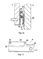
- the slide 39 can be extended from its retracted position shown in FIG. 8 to its extended position shown in FIG. 9, in which the lower side edge 55 is the support surface for the support surface instead of the inclined support surface of the end piece Roller 10 forms so that the front panel 2 of the drawer is raised relative to its position shown in FIG. 8.
- this surrounds the end region of the cut-out catwalk 30 with a step-shaped cutout 56, so that the supporting surfaces of the catwalk 30 and the end piece merge smoothly into one another.
- the lower support surface of the horizontal catwalk 60 is continued by the lower side of a two-part end piece 61.
- This two-part end piece consists of a rear part 62 serving for fastening, which is connected to the front part 64 by a film hinge-like transition or a flexible thin point 63.
- a leg 66 is bent from the web part 65 of the pull-out rail 5, which leg is divided into three parts by incisions 67 which engage in openings 68 of the rear part 62 of the two-part end piece 61 which are adapted to the holder.
- the front part 64 of the two-part end piece 61 is provided with a window-like opening 69 which passes through an eccentric 70 which is rotatably held on the web part 65 of the pull-out rail 5 in that the pin-like extension 71 in a bore 72 of the web part 65 while maintaining the Rotatability is riveted.
- the window-like opening 69 is bordered in steps by a recess 73 in which the head 74 of the eccentric lies, which is provided for its rotation with a screwdriver with a Phillips 75.
- the two-part end piece consists of an injection molded part made of plastic, so that the thin section 63 has the required elasticity.
- a tongue 75 is bent out, which engages in a recess 76 of the front part of the two-piece end piece and has such an inclination that when the front part is pivoted by rotating the eccentric 70, a guide around it the thin point 63 formed pivot axis is created.
- the lower support surface of the catwalk 60 is flush with that through the underside of the rear part 62 of the two-part end piece, the bend 63 creating a smooth transition to the lower support surface 78 of the front part 64, so that a smooth running of the support rollers 10 is ensured when the front part 64 has been pivoted relative to the rear part 62 to adjust the height of the drawer.
Landscapes
- Engineering & Computer Science (AREA)
- Mechanical Engineering (AREA)
- Drawers Of Furniture (AREA)
- Mutual Connection Of Rods And Tubes (AREA)
- Steering Controls (AREA)
- Electrical Discharge Machining, Electrochemical Machining, And Combined Machining (AREA)
- Platform Screen Doors And Railroad Systems (AREA)
- Valve-Gear Or Valve Arrangements (AREA)
- Mechanical Pencils And Projecting And Retracting Systems Therefor, And Multi-System Writing Instruments (AREA)
Applications Claiming Priority (5)
| Application Number | Priority Date | Filing Date | Title |
|---|---|---|---|
| DE20107905U DE20107905U1 (de) | 2001-05-10 | 2001-05-10 | Ausziehführung für eine Schublade |
| DE20107905U | 2001-05-10 | ||
| DE20111017U | 2001-07-03 | ||
| DE20111017U DE20111017U1 (de) | 2001-07-03 | 2001-07-03 | Ausziehführung für eine Schublade |
| EP02008842A EP1256290B1 (fr) | 2001-05-10 | 2002-04-19 | Glissière pour un tiroir |
Related Parent Applications (2)
| Application Number | Title | Priority Date | Filing Date |
|---|---|---|---|
| EP02008842A Division EP1256290B1 (fr) | 2001-05-10 | 2002-04-19 | Glissière pour un tiroir |
| EP02008842.3 Division | 2002-04-19 |
Publications (2)
| Publication Number | Publication Date |
|---|---|
| EP1459652A2 true EP1459652A2 (fr) | 2004-09-22 |
| EP1459652A3 EP1459652A3 (fr) | 2004-10-13 |
Family
ID=26056977
Family Applications (2)
| Application Number | Title | Priority Date | Filing Date |
|---|---|---|---|
| EP02008842A Expired - Lifetime EP1256290B1 (fr) | 2001-05-10 | 2002-04-19 | Glissière pour un tiroir |
| EP04102962A Withdrawn EP1459652A3 (fr) | 2001-05-10 | 2002-04-19 | Glissière pour un tiroir |
Family Applications Before (1)
| Application Number | Title | Priority Date | Filing Date |
|---|---|---|---|
| EP02008842A Expired - Lifetime EP1256290B1 (fr) | 2001-05-10 | 2002-04-19 | Glissière pour un tiroir |
Country Status (12)
| Country | Link |
|---|---|
| US (1) | US6848761B2 (fr) |
| EP (2) | EP1256290B1 (fr) |
| JP (1) | JP3880445B2 (fr) |
| KR (1) | KR100904927B1 (fr) |
| CN (1) | CN1321604C (fr) |
| AT (1) | ATE270061T1 (fr) |
| BR (1) | BR0202473A (fr) |
| DE (1) | DE50200559D1 (fr) |
| ES (1) | ES2223992T3 (fr) |
| HU (1) | HUP0201507A2 (fr) |
| PL (1) | PL198131B1 (fr) |
| TW (1) | TWI229592B (fr) |
Cited By (1)
| Publication number | Priority date | Publication date | Assignee | Title |
|---|---|---|---|---|
| DE202009000665U1 (de) * | 2009-01-20 | 2010-06-10 | Paul Hettich Gmbh & Co. Kg | Schubkastenführung |
Families Citing this family (21)
| Publication number | Priority date | Publication date | Assignee | Title |
|---|---|---|---|---|
| US6923518B2 (en) * | 2003-01-27 | 2005-08-02 | Accuride International Inc. | Drawer slide and drawer slide adjustment mechanism |
| US6945618B2 (en) * | 2003-06-02 | 2005-09-20 | Accuride International Inc. | Drawer slide adjustment mechanism |
| ITMI20031376A1 (it) * | 2003-07-04 | 2005-01-05 | Agostino Ferrari Spa | Guida per cassetti perfezionata. |
| US6902244B1 (en) * | 2003-12-15 | 2005-06-07 | Protrend Co., Ltd. | Drawer rail structure allowing adjusting of vertical position of drawer front panel |
| US20070138924A1 (en) * | 2004-02-21 | 2007-06-21 | Horst Lautenschlager | Adjustment device for furniture fittings |
| US8016374B2 (en) * | 2005-11-10 | 2011-09-13 | Grass Gmbh | Pull-out slide for drawers and drawer |
| DE202006004718U1 (de) * | 2006-03-22 | 2007-08-02 | Grass Gmbh | Vorrichtung für die Bewegungsbeeinflussung von zueinander bewegbaren Möbelteilen und Möbel |
| MX2008006644A (es) * | 2008-05-22 | 2009-11-23 | Mabe Sa De Cv | Sistema de nivelacion para panel o cajon. |
| US8348361B2 (en) * | 2008-06-30 | 2013-01-08 | Electrolux Home Products, Inc. | Additive dispenser drawer assembly |
| JP2010269113A (ja) * | 2009-02-10 | 2010-12-02 | Nifco Inc | 引出しのガイド機構 |
| US8186780B2 (en) * | 2009-11-27 | 2012-05-29 | King Slide Works Co., Ltd. | Adjustment device for slide assembly |
| AT509413B1 (de) * | 2010-02-03 | 2012-12-15 | Blum Gmbh Julius | Neigungsvorrichtung für schubladen |
| AT511294B1 (de) * | 2011-04-11 | 2013-06-15 | Blum Gmbh Julius | Schubladenausziehführung |
| EP2706886B1 (fr) | 2011-05-12 | 2015-07-15 | Inter IKEA Systems B.V. | Rail de guidage coulissant |
| CN104840016B (zh) * | 2014-02-13 | 2017-05-31 | 川湖科技股份有限公司 | 调整装置 |
| CN104172756B (zh) * | 2014-08-20 | 2016-10-05 | 伍志勇 | 一种家具抽屉 |
| DE202014106052U1 (de) * | 2014-12-15 | 2016-03-16 | Grass Gmbh | Vorrichtung zur Führung eines Schubelements und Kücheneinrichtung mit einer solchen Vorrichtung |
| DE102015101006A1 (de) * | 2015-01-23 | 2016-07-28 | Paul Hettich Gmbh & Co. Kg | Auszugsführung, Set aus zwei Auszugsführungen, Möbel und Kraftfahrzeug mit mindestens einer Aufbewahrungseinrichtung |
| CN108272284B (zh) * | 2018-04-01 | 2024-03-19 | 上海古鳌电子科技股份有限公司 | 一种方便取用的印鉴卡机柜及工作方法 |
| US20230011459A1 (en) * | 2021-07-12 | 2023-01-12 | Xiaofeng Liu | Multi-purpose coffee capsule storage drawer |
| JP2024089737A (ja) * | 2022-12-22 | 2024-07-04 | 沖電気工業株式会社 | 媒体取扱装置 |
Citations (2)
| Publication number | Priority date | Publication date | Assignee | Title |
|---|---|---|---|---|
| DE2752779C2 (de) | 1976-12-10 | 1985-11-07 | Julius Blum GmbH, Höchst | Ausziehführung für Schubladen o.dgl. |
| EP0406703A1 (fr) | 1989-07-06 | 1991-01-09 | Arturo Salice S.p.A. | Glissières pour tiroirs ou similaires |
Family Cites Families (20)
| Publication number | Priority date | Publication date | Assignee | Title |
|---|---|---|---|---|
| CH496402A (fr) | 1969-03-07 | 1970-09-30 | Nestle Sa | Procédé de fabrication d'un fondant-sucré de confiserie |
| DE6934139U (de) | 1969-08-29 | 1970-01-15 | Robert Krause Kg Werk Fuer Moe | Ausziehsperrvorrichtungsbeschlag fuer raumteiler-schubkaesten |
| AT328127B (de) * | 1974-05-27 | 1976-03-10 | Grass Alfred Metallwaren | Schubladenfuhrung |
| DE3120840A1 (de) * | 1981-01-29 | 1982-09-09 | Alfred Grass GmbH Metallwarenfabrik, 6973 Höchst, Vorarlberg | Blendeneinstellelement fuer die frontblende bei schubladen, auszuegen oder dergleichen |
| DE3221073A1 (de) * | 1982-06-04 | 1983-12-08 | Kurz, Richard, 7000 Stuttgart | Schublade |
| ATA105783A (de) * | 1983-03-25 | 1990-11-15 | Grass Alfred Metallwaren | Ausziehfuehrung fuer schubladen od. dgl. |
| US4615572A (en) * | 1983-09-20 | 1986-10-07 | Nelson Gary W | Cantilevered drawer slide arrangement |
| HU188980B (hu) | 1983-11-11 | 1986-05-28 | Lencses,Laszlo,Hu | Fiókszerú elemek saját vagy nem saját anyagukból kialakított gördülövezetékekkel |
| HU193475B (hu) | 1985-02-21 | 1987-10-28 | Gusztav Drevenka | Bútorfiók kettős kihúzható fémvezetékkel |
| JPH033216Y2 (fr) * | 1986-05-13 | 1991-01-28 | ||
| JPH033223Y2 (fr) * | 1986-06-30 | 1991-01-28 | ||
| JPH01119537A (ja) * | 1987-11-02 | 1989-05-11 | Mitsubishi Kasei Corp | 透明石英ガラス成形体の製造方法 |
| DE9013161U1 (de) | 1990-09-17 | 1990-11-22 | Paul Hettich GmbH & Co, 4983 Kirchlengern | Vorrichtung zum Halten eines in einen Möbelkorpus eingeschobenen Schubkastens |
| US5653518A (en) * | 1993-09-10 | 1997-08-05 | Compaq Computer Corporation | Quick release drive unit rail members |
| US5556182A (en) * | 1995-06-12 | 1996-09-17 | Lai; Pepper Y. | Cabinet drawer guide assemblies |
| AT405360B (de) * | 1995-09-07 | 1999-07-26 | Alfit Ag | Vorrichtung zur einstellbaren befestigung der frontblende einer schublade an deren zargen |
| US5876103A (en) * | 1996-06-05 | 1999-03-02 | Grass America, Inc. | Self-positioning cabinet rail for a drawer guide |
| DE19957072A1 (de) | 1999-11-26 | 2001-06-13 | Rainer Grob | Vorrichtung zur Justierung und Fixierung zweier Möbelteile aneinander |
| CN2424677Y (zh) * | 2000-05-12 | 2001-03-28 | 潘建芳 | 改进的抽屉面板连接器 |
| DE20107905U1 (de) * | 2001-05-10 | 2001-07-26 | Arturo Salice S.P.A., Novedrate, Como | Ausziehführung für eine Schublade |
-
2002
- 2002-04-16 TW TW091107703A patent/TWI229592B/zh not_active IP Right Cessation
- 2002-04-19 EP EP02008842A patent/EP1256290B1/fr not_active Expired - Lifetime
- 2002-04-19 EP EP04102962A patent/EP1459652A3/fr not_active Withdrawn
- 2002-04-19 DE DE50200559T patent/DE50200559D1/de not_active Expired - Lifetime
- 2002-04-19 ES ES02008842T patent/ES2223992T3/es not_active Expired - Lifetime
- 2002-04-19 AT AT02008842T patent/ATE270061T1/de active
- 2002-04-30 JP JP2002128715A patent/JP3880445B2/ja not_active Expired - Fee Related
- 2002-05-07 HU HU0201507A patent/HUP0201507A2/hu unknown
- 2002-05-07 KR KR1020020024979A patent/KR100904927B1/ko not_active Expired - Fee Related
- 2002-05-09 PL PL353783A patent/PL198131B1/pl unknown
- 2002-05-10 US US10/143,346 patent/US6848761B2/en not_active Expired - Lifetime
- 2002-05-10 CN CNB021199426A patent/CN1321604C/zh not_active Expired - Fee Related
- 2002-05-10 BR BR0202473-0A patent/BR0202473A/pt not_active Application Discontinuation
Patent Citations (2)
| Publication number | Priority date | Publication date | Assignee | Title |
|---|---|---|---|---|
| DE2752779C2 (de) | 1976-12-10 | 1985-11-07 | Julius Blum GmbH, Höchst | Ausziehführung für Schubladen o.dgl. |
| EP0406703A1 (fr) | 1989-07-06 | 1991-01-09 | Arturo Salice S.p.A. | Glissières pour tiroirs ou similaires |
Cited By (1)
| Publication number | Priority date | Publication date | Assignee | Title |
|---|---|---|---|---|
| DE202009000665U1 (de) * | 2009-01-20 | 2010-06-10 | Paul Hettich Gmbh & Co. Kg | Schubkastenführung |
Also Published As
| Publication number | Publication date |
|---|---|
| TWI229592B (en) | 2005-03-21 |
| JP3880445B2 (ja) | 2007-02-14 |
| PL198131B1 (pl) | 2008-05-30 |
| HU0201507D0 (fr) | 2002-07-29 |
| DE50200559D1 (de) | 2004-08-05 |
| BR0202473A (pt) | 2003-10-28 |
| ES2223992T3 (es) | 2005-03-01 |
| JP2002360359A (ja) | 2002-12-17 |
| KR100904927B1 (ko) | 2009-06-29 |
| EP1256290A1 (fr) | 2002-11-13 |
| CN1321604C (zh) | 2007-06-20 |
| US6848761B2 (en) | 2005-02-01 |
| CN1385129A (zh) | 2002-12-18 |
| US20020190618A1 (en) | 2002-12-19 |
| ATE270061T1 (de) | 2004-07-15 |
| PL353783A1 (en) | 2002-11-18 |
| EP1256290B1 (fr) | 2004-06-30 |
| EP1459652A3 (fr) | 2004-10-13 |
| HUP0201507A2 (hu) | 2003-08-28 |
| HK1051301A1 (en) | 2003-08-01 |
| KR20020086241A (ko) | 2002-11-18 |
Similar Documents
| Publication | Publication Date | Title |
|---|---|---|
| EP1459652A2 (fr) | Glissière pour un tiroir | |
| DE3820338C2 (fr) | ||
| DE19920137A1 (de) | Montageplatte für Möbelscharniere | |
| EP1084661A1 (fr) | Système de cloisonnement | |
| WO1994001019A1 (fr) | Kit de tiroir | |
| EP0052283B1 (fr) | Bras de charnière ayant une plaque de montage | |
| DE4016664A1 (de) | Scharnier | |
| EP0894929A2 (fr) | Plaque de montage pour une ferrure, en particulier pour la fixation d'un bras de charnière sur une paroi de meuble | |
| WO1994018870A1 (fr) | Ferrure de fixation pour les panneaux avant de tiroirs | |
| DE10254772A1 (de) | Blendeneinstellvorrichtung | |
| AT393403B (de) | Montageplatte fuer moebelbeschlaege, insbesondere moebelscharniere | |
| DE4134828A1 (de) | Montageplatte fuer moebelscharniere | |
| EP2064972B1 (fr) | Tiroir d'armoire doté d'une partie de support et d'une façade de meuble pouvant être fixée dessus | |
| EP1454026B1 (fr) | Plaque de montage pour la fixation reglable de charnieres de meuble sur le corps de meubles | |
| AT524414A4 (de) | Möbelbeschlag und Möbel mit einem solchen Möbelbeschlag | |
| DE20111017U1 (de) | Ausziehführung für eine Schublade | |
| AT402998B (de) | Schubladenausziehführung für rahmenmöbel | |
| CH715007B1 (de) | Schubladenauszug mit Auszugsbegrenzung. | |
| DE3505614C2 (fr) | ||
| DE19650062C2 (de) | Möbelscharnier | |
| DE4233402C2 (de) | Befestigungsvorrichtung für Schienen mit Reihen von Durchbrüchen und Bohrungen | |
| AT398263B (de) | Auszugschiene mit einer integrierten seitenzarge | |
| DE20211803U1 (de) | Vorrichtung zur Höhenverstellung einer Schublade | |
| EP4537708B1 (fr) | Dispositif de suspension | |
| DE2420307A1 (de) | Rollenfuehrung fuer moebelschubkaesten |
Legal Events
| Date | Code | Title | Description |
|---|---|---|---|
| PUAI | Public reference made under article 153(3) epc to a published international application that has entered the european phase |
Free format text: ORIGINAL CODE: 0009012 |
|
| PUAL | Search report despatched |
Free format text: ORIGINAL CODE: 0009013 |
|
| AC | Divisional application: reference to earlier application |
Ref document number: 1256290 Country of ref document: EP Kind code of ref document: P |
|
| AK | Designated contracting states |
Kind code of ref document: A2 Designated state(s): AT DE ES FR GB IT |
|
| AK | Designated contracting states |
Kind code of ref document: A3 Designated state(s): AT DE ES FR GB IT |
|
| RIC1 | Information provided on ipc code assigned before grant |
Ipc: 7A 47B 88/14 B Ipc: 7A 47B 88/00 A |
|
| RIN1 | Information on inventor provided before grant (corrected) |
Inventor name: DER ERFINDER HAT AUF SEINE NENNUNG VERZICHTET. |
|
| 17P | Request for examination filed |
Effective date: 20050315 |
|
| AKX | Designation fees paid |
Designated state(s): AT DE ES FR GB IT |
|
| STAA | Information on the status of an ep patent application or granted ep patent |
Free format text: STATUS: THE APPLICATION IS DEEMED TO BE WITHDRAWN |
|
| 18D | Application deemed to be withdrawn |
Effective date: 20081031 |