EP1459849B1 - Sicherheitsvorrichtung für druckluftschlagschrauber - Google Patents
Sicherheitsvorrichtung für druckluftschlagschrauber Download PDFInfo
- Publication number
- EP1459849B1 EP1459849B1 EP02762756A EP02762756A EP1459849B1 EP 1459849 B1 EP1459849 B1 EP 1459849B1 EP 02762756 A EP02762756 A EP 02762756A EP 02762756 A EP02762756 A EP 02762756A EP 1459849 B1 EP1459849 B1 EP 1459849B1
- Authority
- EP
- European Patent Office
- Prior art keywords
- valve
- port
- air
- contact
- pilot
- Prior art date
- Legal status (The legal status is an assumption and is not a legal conclusion. Google has not performed a legal analysis and makes no representation as to the accuracy of the status listed.)
- Expired - Lifetime
Links
Images



Classifications
-
- B—PERFORMING OPERATIONS; TRANSPORTING
- B25—HAND TOOLS; PORTABLE POWER-DRIVEN TOOLS; MANIPULATORS
- B25B—TOOLS OR BENCH DEVICES NOT OTHERWISE PROVIDED FOR, FOR FASTENING, CONNECTING, DISENGAGING, OR HOLDING
- B25B21/00—Portable power-driven screw or nut setting or loosening tools; Attachments for drilling apparatus serving the same purpose
- B25B21/02—Portable power-driven screw or nut setting or loosening tools; Attachments for drilling apparatus serving the same purpose with means for imparting impact to screwdriver blade or nut socket
- B25B21/023—Portable power-driven screw or nut setting or loosening tools; Attachments for drilling apparatus serving the same purpose with means for imparting impact to screwdriver blade or nut socket for imparting an axial impact, e.g. for self-tapping screws
-
- B—PERFORMING OPERATIONS; TRANSPORTING
- B25—HAND TOOLS; PORTABLE POWER-DRIVEN TOOLS; MANIPULATORS
- B25B—TOOLS OR BENCH DEVICES NOT OTHERWISE PROVIDED FOR, FOR FASTENING, CONNECTING, DISENGAGING, OR HOLDING
- B25B21/00—Portable power-driven screw or nut setting or loosening tools; Attachments for drilling apparatus serving the same purpose
- B25B21/02—Portable power-driven screw or nut setting or loosening tools; Attachments for drilling apparatus serving the same purpose with means for imparting impact to screwdriver blade or nut socket
-
- B—PERFORMING OPERATIONS; TRANSPORTING
- B25—HAND TOOLS; PORTABLE POWER-DRIVEN TOOLS; MANIPULATORS
- B25B—TOOLS OR BENCH DEVICES NOT OTHERWISE PROVIDED FOR, FOR FASTENING, CONNECTING, DISENGAGING, OR HOLDING
- B25B21/00—Portable power-driven screw or nut setting or loosening tools; Attachments for drilling apparatus serving the same purpose
- B25B21/02—Portable power-driven screw or nut setting or loosening tools; Attachments for drilling apparatus serving the same purpose with means for imparting impact to screwdriver blade or nut socket
- B25B21/026—Impact clutches
-
- B—PERFORMING OPERATIONS; TRANSPORTING
- B25—HAND TOOLS; PORTABLE POWER-DRIVEN TOOLS; MANIPULATORS
- B25C—HAND-HELD NAILING OR STAPLING TOOLS; MANUALLY OPERATED PORTABLE STAPLING TOOLS
- B25C1/00—Hand-held nailing tools; Nail feeding devices
- B25C1/008—Safety devices
Definitions
- the present invention relates to an air impact driver as per the preamble of claim 1.
- An example of such driver is disclosed by EP774325A .
- An air impact driver provided for screwing a building material of a plaster board or the like is mounted with a mechanical type safety apparatus by a contact arm similar to a nail striker.
- the contact arm is an arm formed in a crank-like shape along outer shapes of a nose and a cylinder housing of the air impact driver which is slidable in parallel with the nose, a front end thereof is projected frontward from the nose and other end reaches a front face of a trigger lever of a main body of the air impact driver.
- a trigger lever is attached with a pivotable free arm and when the contact arm is pressed to a side of the main body of the air impact driver, a front end portion of the free arm attached to the trigger lever is pressed by the contact arm to be proximate to a stem of a trigger valve.
- the free arm is pivoted in a direction of the trigger valve by constituting a fulcrum by the front end portion along with the trigger lever and the stem of the trigger valve is pressed by the free arm to start the air impact driver.
- the free arm presses the stem of the trigger arm to start to the air impact driver similar to the above-described operation.
- the trigger lever and the contact arm are constituted to cooperatively make the trigger valve ON, when only the trigger lever is operated, the free arm does not reach a position of the stem of the trigger arm and the air impact driver cannot be started to thereby prevent the air impact driver from being started by erroneously operating the trigger lever.
- the contact arm passes a side face of the cylinder housing and therefore, a width of a total of the air impact driver is widened and there is a case in which it is difficult to strike a screw to a corner portion or a location having a narrow width.
- the front end of the free arm attached to the trigger lever is pressed up by sliding the contact arm and the total of the free arm is moved by pulling the trigger lever to thereby press the stem of the trigger valve, there poses a problem that the stroke of pressing the contact arm isprolongedandtherefore, operability is not excellent, further, operation of one cycle is devoid of swiftness.
- EP 774 325 A1 discloses an air impact driver according to the preamble of claim 1.
- a technical problem to be resolved is posed for providing an air impact driver improving difficulty in fastening screw to a corner portion or a narrow portion and general operability owing to the above-described problem and it is an object of the invention to resolve the above-described problem.
- numeral 1 designates an air impact driver
- numeral 5 designates a nose
- numeral 8 designates a trigger valve
- numeral 9 designates a trigger lever
- numeral 12 designates a contact nose
- numeral 13 designates an air cylinder
- numeral 14 designates a piston
- numeral 15 designates a hexagonal shaft
- numeral 17 designates an impact mechanism
- numeral 19 designates an air motor
- numeral 22 designates a rod
- numeral 23 designates a contact valve
- notation 23a designates a spool
- numeral 33 designates an air motor switch valve
- numeral 39 designates an air motor controlling pilot valve
- numeral 41 designates a piston controlling pilot valve
- numeral 52 designates a poppet valve
- numeral 71 designates a contact valve
- numeral 72 designates a cylinder portion
- numeral 73 designates a spool
- numeral 81 designates a contact valve
- numeral 82 designates a cylinder portion
- Fig. 1 through Fig. 4 show the air impact driver 1 which is constituted by a cabinet structure connected with an air motor housing 2, a clutch housing 3, a cylinder housing 4, and the nose 5 in one row from above and attached with a grip 6 extended from the clutch housing 3 in a direction orthogonal thereto.
- an air plug is attached to an end portion of the grip 6 although illustration thereof is omitted, an air hose is connected to the air plug and high pressure air is supplied from an air compressor to an air chamber 7 at inside of the grip 6.
- a base portion of the grip 6 is provided with the trigger valve 8 and the trigger lever 9 and the air impact driver 1 is started and stopped by opening and closing the trigger valve 8 by operating the trigger lever 9.
- a back face (right side of drawing) of the nose 5 is provided with a known connecting screw feeding apparatus comprising a spring offset type air cylinder 10 and a feed claw 11 connected to a piston rod thereof and a connecting screw at inside of a connecting screw magazine (not illustrated) is fed into the nose 5 by moving the feeding claw 11 forward and rearward in cooperation with one cycle operation of the air impact driver 1.
- a portion A on a right upper side of the drawing is the sectional view viewing a portion of the trigger valve 8 from a right side
- a portion B on a left lower side thereof is a sectional view viewing a portion of the contact nose 12 from a left side and air pipes are indicated by chain lines.
- the piston 14 of the air cylinder 13 included in the cylinder housing 4 is attached with the driver bit 15 at a front face (lower side of the drawing) thereof and attached with the hexagonal shaft 16 at a back face (upper side of the drawing) thereof.
- the impact mechanism 17 of a centrifugal meshing type is included in the clutch housing 3, a hexagonal hole is formed at a center of a driven rotating member 18 (hereinafter, referred to as anvil) having a horizontal section in a butterfly-like shape arranged at a center thereof and the hexagonal hole is penetrated by the hexagonal shaft 16.
- the rotor 20 of the air motor 19 arranged above the impact mechanism 17 is provided with a center hole having a diameter larger than that of the hexagonal shaft 16 and an upper portion o'f the hexagonal shaft 16 advances into the center hole.
- the piston 14 and the driver bit 15 and the hexagonal shaft 16 are rotated around an axis along with the anvil 18 of the impact mechanism 17 and made to be liftable at inside of the air cylinder 13.
- the rotor 20 of the air motor 19 is coupled to an outer rotor 21 of the impact mechanism 17 and the both members are integrally rotated.
- the outer rotor 21 is pivotably attached with a hammer 21a of a lever type.
- a rear side in a rotational direction of the hammer 21a is pivoted in a rotational center direction by static inertia and a corner portion of the rear side is brought into contact with the anvil 18 as shown by Fig.
- a corner portion on a front side in the rotational direction thereof is pivoted in the rotational center direction to be brought in mesh with the projected portion of the anvil 18 to rotate while impacting the anvil 18.
- Fig. 5(e) the corner portion of the front side of the hammer 21a is detached from the anvil 18 and as shown by Fig. 5(b) , the corner portion on the rear side is brought into contact with the anvil 18.
- the hammer 21a is circulated at high speed in a swinging cycle of Fig. 5 (b) through Fig. 5(e) to continuously strike the anvil 18 in the rotational direction to thereby rotate the hexagonal shaft 16 and the piston 14 and the driver bit 15.
- the contact nose 12 of Fig. 1 will be explained.
- the contact nose 12 fitted to an outer peripheral face of a front end portion of the nose 5 can be slid upwardly relative to the nose 5.
- the contact nose 12 is attached with the rod 22 to direct to an upper side thereof and a front end of the rod 22 is brought into a rod guide hole of the contact valve 23 provided at a lower portion of the cylinder housing 4 to be brought into contact with a stem 24 at inside of the rod guide hole.
- a stroke adjusting dial 25 is attached to a center of a front face of the contact nose 12 and a stopper 26 formed at the nose 5 is disposed upward from the stroke adjusting dial 25.
- a rear face of the stroke adjusting dial 25 is formed with a cam portion 27 a radius from a rotational center of which is changed in steps (8 steps in the illustrated example) by a rotational angle thereof.
- a clip stop mechanism of 8 steps is formed by springs (not illustrated) and balls 28 inserted into holes at a rear face of the stroke adjusting dial 25 and ball receiving holes 29 aligned in a ring-like shape at a front face of the contact nose 12 to thereby fix the stroke adjusting dial 25 at every constant rotational angle.
- the stopper 26 provided at the nose 5 is opposed to an outer peripheral face of the cam portion 27 of the stroke adjusting dial 25 and when the contact nose 12 is slid to an upper side, the outer peripheral face of the cam portion 27 is brought into contact with the stopper 26 to stop the contact nose 12.
- the radius of the cam portion 27 brought into contact with the stopper 26 differs by the rotational angle of the stroke adjusting dial 25 and therefore, a stroke of sliding the contact nose 12 to the upper side can be adjusted in 8 steps by rotating the stroke adjusting dial 25 to arbitrary click positions, thereby, a depth of fastening the screw can be adjusted.
- Fig. 1 shows a standby state, a stem 30 of the trigger valve 8 is moved down to a closed position and a puppet 31 coaxial with the stem 30 is moved up by a spring and a pneumatic pressure operated to a lower face thereof.
- An intake port 32 of the air motor 19 is connected with the air motor switching valve 33, an input port 34 of the air motor switching valve 33 is connected to an upper output port 35 of the trigger valve 8, an upper pilot port 36 is connected to an upper output port 37 of the trigger valve 8 shown in the portion A, and a lower pilot port 38 is connected to the air motor controlling pilot valve 39.
- An upper pilot port 40 of the air motor controlling pilot valve 39 and an upper pilot port 42 of the piston controlling pilot valve 41 on the left are connected to the upper output port 37 of the trigger valve 8 shown in the portion A.
- An upper port 43 of the air cylinder 13 and a front port 44 of the spring offset type air cylinder 10 of the connecting screw feeding apparatus are connected to the lower port 45 of the piston controlling pilot valve 41 and a lower port 46 of the air cylinder 13 is connected to a lower port 47 of the trigger valve 8 shown in the portion A.
- a lower port 48 of the contact valve 23 arranged at a lower portion of the cylinder housing 4 is connected to an upper port 49 of the piston controlling pilot valve 41 and an upper port 50 of the contact valve 23 is connected to an air chamber connecting port 51 shown in the portion A.
- the lower port 48 of the contact valve 23 and the small-sized poppet valve 52 arranged to be contiguous to the contact valve 23 are communicated via a clearance at an outer periphery of the contact valve 23 and the poppet valve 52 opens and closes a path 54 communicating with an upper port 53 of the motor controlling pilot valve 39.
- the small-sized poppet valve 52 arranged to be contiguous to the contact valve 23 and the lower port 48 of the contact valve 23 are communicated via the clearance at the outer periphery of the contact valve 23 and the poppet valve 52 opens and closes the path 54 to the upper port 53 of the air motor controlling pilot valve 39.
- the spool 23a of the contact valve 23 is formed with an exhausting path 23b communicating an outer peripheral face of a middle portion thereof to a bottom face thereof on a side of the stem 24 and at an initial position shown in Fig. 6 , the lower port 48 constituting a secondary side path is communicated with the atmosphere via the exhausting path 23b of the spool 23a.
- Fig. 2 and Fig. 7 show a state of bringing the contact nose 12 into contact with an object face of screwing to press, the spool 23a of the contact valve 23 is pushed up by the rod 22 of the contact nose 22 to communicate the upper port 50 and the lower port 48, pressurized air is supplied to an air chamber of the piston controlling pilot valve 42 via the lower port 48, as shown by Fig. 2 , a spool of the piston controlling pilot valve 41 is moved up to cut the upper port 49 and the lower port 45.
- pressurized air pushes up the poppet valve 52 via the path of the outer periphery of the contact valve 23
- pressurized air is supplied to an air chamber of the air motor controlling pilot valve 39 via the output path 54, and a spool is moved up to maintain a state of cutting the upper port 53 and the lower port 55.
- the stem 30 of the trigger valve 8 is moved up to communicate the upper ports 35, 37 of the trigger valve 8, pressurized air operated to a lower face of the poppet 31 is exhausted from a surrounding of the stem 30 to a lower side to move down the poppet 31 and air at the lower air chamber of the air cylinder 13 is exhausted to the atmosphere via the trigger valve 8.
- pressurized air is supplied to the input port 34 of the air motor switching valve 33 via the upper port 35 of the trigger valve 8, and a pilot pressure is applied to the upper pilot port 36 of the air motor switching valve 33, the pilot port 40 of the air motor controlling pilot valve 39 and the pilot port 42 of the piston controlling pilot valve 41.
- a pilot pressure is applied to the upper pilot port 36 of the air motor switching valve 33, the pilot port 40 of the air motor controlling pilot valve 39 and the pilot port 42 of the piston controlling pilot valve 41.
- pressurized air is supplied to the lower pilot port 38 of the air motor switching valve 33 via the lower port 55 of the air motor controlling pilot valve 39, the spool 56 of the air motor switching valve 33 is moved up and after moving down the piston 14, the air motor 19 is started and the piston 14 and the driver bit and the hexagonal shaft 16 start rotating, when the air motor 19 is started, the anvil 18 and the hexagonal shaft 16, the piston 14, the driver bit 15 are rotated by high speed impact operation of the impact mechanism 17 and the screw is fastened to the object of screwing.
- Fig. 4 shows a state of finishing to screw and the piston 14 reaches a lower end of a movable range to push down a bumper 57 at inside of the air cylinder 13 and the poppet valve 52 at a bottom portion thereof.
- pressurized air supplied to the lower air chamber of the air motor switching valve 33 via the air motor controlling pilot valve 39 is exhausted from the trigger valve 8 via the poppet 52 and the lower port 46 of the air cylinder.
- the air pressure operated to the lower face of the spool 56 of the air motor switching valve 33 is reduced to move down the spool 56 and the input port 32 of the air motor 19 and the air chamber 7 are cut to stop rotating the air motor 19.
- the stem 30 of the trigger valve 8 is moved down to the initial position, pressurized air is brought into the lower face of the poppet 31 to move up the poppet 31, pressurized air is supplied from the air chamber 7 to the lower air chamber of the air cylinder 13 via the lower port 47 of the trigger valve 8 and the piston 14 is moved up to return to the initial position.
- pressurized air is not supplied from the air motor controlling pilot valve 39 to the lower pilot port 38 of the air motor switching valve 33 in cooperation with operation of the piston controlling pilot valve 41 and therefore, the spool 56 of the air motor switching valve 33 is moved down by the pilot pressure applied to the upper pilot port 36 to cut the input port 32 of the air motor 19 and the air chamber 17 and therefore, the air motor 19 is not started and the air impact driver can be prevented from being started by erroneously operating the trigger lever similar to the mechanical type safety apparatus of the prior art.
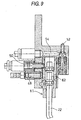
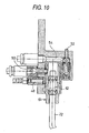
- a spool 62 of a contact valve 61 is not provided with a path as shown by an initial state of Fig. 8 through Fig. 9 , when the contact valve 61 is opened, similar to the contact valve 23 of Fig. 6 and Fig. 7 , pressurized air is supplied to the air chamber of the piston controlling pilot valve 41 and the air chamber of the air motor controlling pilot valve 39.
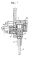
- Fig. 11 through Fig. 4 show other embodiment of a contact valve according to the invention, and according to the contact valve 71 shown in Fig. 11 , an inner diameter of a lower portion of the cylinder portion 72 is made to be larger than an outer diameter of the spool 73. Therefore, when the spool 73 returns to the initial position, pressurized air remaining at the air chamber of the piston controlling pilot valve 41 and the air chamber of the air motor controlling pilot valve 39 is exhausted to the atmosphere via an exhaust path at a clearance between the lower portion of the cylinder portion 72 and the spool 73. As shown by Fig.
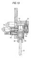
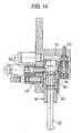
- the contact valve 81 shown in Fig. 13 and Fig. 14 is formed with the vent hole 83 at a lower portion of the cylinder portion 82 and as shown by Fig. 13 , when the spool returns to the initial position, pressurized air remaining in the air chamber of the piston controlling pilot valve 41 and the air chamber of the air motor controlling pilot valve 39 is exhausted to the atmosphere via the vent hole 83. As shown by Fig.
- the safety apparatus of the air impact driver of the invention is constituted to operate the control valve for starting the air impact driver by the trigger valve operated by the trigger lever and the contact valve operated to slide by the contact nose and therefore, the long contact arm reaching the trigger lever from the nose of the mechanical type safety apparatus of the background art is dispensed with, the width of the air impact driver can be narrowed to be able to deal with a corner portion or a location having a narrow width at which operation has been difficult in the background art.
- the contact nose is constituted to operate the valve and therefore, the stroke of the contact nose is extremely shortened and operability and operational efficiency are promoted.
Landscapes
- Engineering & Computer Science (AREA)
- Mechanical Engineering (AREA)
- Portable Nailing Machines And Staplers (AREA)
- Details Of Spanners, Wrenches, And Screw Drivers And Accessories (AREA)
Claims (3)
- Druckluft-Schlagschrauber, umfassend:einen Schrauber-Einsatz (15) zum Befestigen einer Schraube;eine Kontakt-Nase (12) gleitbar relativ zu einer Nase (5),einen Abzugs-Hebel (9),ein Kontakt-Ventil (23, 61, 71, 81), das mit der Kontakt-Nase (12) verbunden ist; undein Abzugs-Ventil (8), das über den Abzugs-Hebel (9) betrieben wird;einen Druckluft-Motor (19) zum Drehen des Schrauber-Einsatzes (15);einen Luftzylinder (13) zum Herabbewegen des Schrauber-Einsatzes (15);ein Druckluft-Motor-Schaltventil (33), das mit dem Druckluft-Motor (19) verbunden ist;gekennzeichnet überein kolbensteuerndes Steuerventil (41), das mit dem Druckluft-Zylinder (13) verbunden ist; undein motorsteuerndes Steuerventil (39),wobei das Abzugs-Ventil (8) obere Ausgabe-Durchlässe (35, 37) umfasst und einen Druckluftkammer verbindenden Anschluss (51),wobei das Kontakt-Ventil (23, 61, 71, 81) einen oberen Anschluss (50), einen unteren Anschluss (48) und einen Verbindungsweg (54) umfasst, und wobei der obere Anschluss (50) mit dem Druckluft-Kammer verbindenden Anschluss (51) verbunden ist,wobei das kolbensteuernde Steuerventil (41) einen oberen Anschluss (49), einen unteren Anschluss (45) und einen Steuer-Anschluss (42) umfasst, und wobei der obere Anschluss (49) mit dem unteren Anschluss (48) des Kontakt-Ventils (23, 61, 71, 81) verbunden ist, der untere Anschluss (45) mit dem Druckluft-Zylinder (13) verbunden ist, und der Steuer-Anschluss (42) mit dem oberen Ausgabe-Anschluss (37) des Abzugs-Ventils (8) verbunden ist,wobei das motorsteuernde Steuerventil (39) einen oberen Anschluss (53), einen unteren Anschluss (55) und einen Steuer-Anschluss (40) umfasst, und wobei der obere Anschluss (53) mit dem Verbindungsweg (54) des Kontakt-Ventils (23, 61, 71, 81) verbunden ist, und der Steuer-Anschluss (40) mit dem oberen Ausgabe-Anschluss (37) des Abzugs-Ventils (8) verbunden ist,wobei das Druckluft-Motor-Schaltventil (33) einen Eingangs-Anschluss (34), einen oberen Steuer-Anschluss (36) und einen unteren Steuer-Anschluss (38) umfasst, und wobei der Eingangs-Anschluss (34) mit dem oberen Ausgabe-Anschluss (37) des Abzugs-Ventils (8) verbunden ist, und der untere Steuer-Anschluss (38) mit dem unteren Anschluss (55) des motorsteuernden Steuerventils (39),wobei der Druckluft-Zylinder (13) derart konfiguriert ist, dass mit Druck beaufschlagte Luft von dem unteren Element (48) des Kontaktventils (23, 61, 71, 81) über das kolbensteuernde Steuerventil (41) zu dem Druckluft-Zylinder (13) zugeführt wird, um den Schrauber-Einsatz (15) über ein Pressen der Kontakt-Nase (12) herabzubewegen, um so den oberen Anschluss (50) und den unteren Anschluss (48) des Kontakt-Ventils (23, 61, 71, 81) miteinander in Verbindung zu bringen und um die mit Druck beaufschlagte Luft zu dem kolbensteuernden Steuerventil (41) von dem unteren Anschluss (48) zuzuführen, und über ein Betätigen des Abzugs-Hebels (9), um so einen Steuer-Druck auf den Steuer-Anschluss (42) des kolbensteuernden Steuerventils (41) von dem oberen Anschluss (37) des Abzugs-Ventils (8) anzuwenden, undwobei der Druckluft-Motor (19) über ein Drücken der Kontakt-Nase (12) zum Starten konfiguriert ist, um die mit Druck beaufschlagte Luft zu dem motorsteuernden Steuerventil (39) über den Ausgabe- Verbindungsweg (54) des Kontakt-Ventils (23, 61, 71, 81) zuzuführen, und über ein Ziehen des Abzugs-Hebels (9), um die mit Druck beaufschlagte Luft zu dem Eingabe-Anschluss (34) des Druckluft-Motors-Schalt-Ventils (33) über den oberen Ausgabe-Anschluss (35) des Abzugs-Ventils (8) zuzuführen, um den Steuerdruck auf den oberen Steuer-Anschluss (36) des Druckluft-Motor-Schalt-Ventils (33) anzuwenden, um den Steuer-Druck auf den Steuer-Anschluss (40) des Druckluftmotor-steuernden Steuerventils (39) anzuwenden, und um die mit Druck beaufschlagte Luft zu dem unteren Steuer-Anschluss (38) des Druckluftmotor-Schalt-Ventils (33) über den unteren Anschluss (55) des Druckluftmotor steuernden Steuerventils (39) zuzuführen.
- Druckluft-Schlagschrauber gemäß Anspruch 1, bei dem das Kontakt-Ventil (23, 61, 71, 81) betrieben wird, um über ein Bewegen zu schalten, um die Kontaktnase (12) gleiten zu lassen.
- Druckluft-Schlagschrauber gemäß Anspruch 1, bei dem das Kontakt-Ventil (23, 61, 71, 81) ein Schalt-Ventil (23, 61, 71, 81) ist, das einen zweiten Seiten-Auslass mit einem ersten Seiten-Einlass in Verbindung bringt, wenn das Kontakt-Ventil in einer An-Position angeordnet ist, und das den zweiten Seiten-Auslass mit der Atmosphäre in Verbindung bringt, wenn das Kontakt-Ventil in einer Aus-Position angeordnet ist.
Applications Claiming Priority (5)
| Application Number | Priority Date | Filing Date | Title |
|---|---|---|---|
| JP2001241323 | 2001-08-08 | ||
| JP2001241323A JP4720043B2 (ja) | 2001-08-08 | 2001-08-08 | エアインパクトドライバの安全装置 |
| JP2001241331 | 2001-08-08 | ||
| JP2001241331A JP2003048175A (ja) | 2001-08-08 | 2001-08-08 | エアインパクトドライバの安全装置 |
| PCT/JP2002/008074 WO2003013796A1 (en) | 2001-08-08 | 2002-08-07 | Safety device of air impact screwdriver |
Publications (3)
| Publication Number | Publication Date |
|---|---|
| EP1459849A1 EP1459849A1 (de) | 2004-09-22 |
| EP1459849A4 EP1459849A4 (de) | 2009-07-29 |
| EP1459849B1 true EP1459849B1 (de) | 2011-12-21 |
Family
ID=26620220
Family Applications (1)
| Application Number | Title | Priority Date | Filing Date |
|---|---|---|---|
| EP02762756A Expired - Lifetime EP1459849B1 (de) | 2001-08-08 | 2002-08-07 | Sicherheitsvorrichtung für druckluftschlagschrauber |
Country Status (4)
| Country | Link |
|---|---|
| US (1) | US7104433B2 (de) |
| EP (1) | EP1459849B1 (de) |
| TW (1) | TW529980B (de) |
| WO (1) | WO2003013796A1 (de) |
Families Citing this family (8)
| Publication number | Priority date | Publication date | Assignee | Title |
|---|---|---|---|---|
| WO2006132684A2 (en) * | 2005-02-25 | 2006-12-14 | Duraspin Products Llc | Portable screw driving tool with collapsible front end |
| JP4362657B2 (ja) * | 2005-09-07 | 2009-11-11 | ヨコタ工業株式会社 | 電動式衝撃締め付け工具 |
| JP4891672B2 (ja) * | 2006-06-30 | 2012-03-07 | 日東精工株式会社 | ねじ部品締結機 |
| US8095438B2 (en) * | 2007-12-28 | 2012-01-10 | Mastercard International Incorporated | Methods and systems for assigning interchange rates to financial transactions using an interchange network |
| US8800835B2 (en) * | 2008-07-17 | 2014-08-12 | Stanley Fastening Systems, Lp | Fastener driving device with mode selector and trigger interlock |
| US20100038398A1 (en) * | 2008-08-17 | 2010-02-18 | Chia-Sheng Liang | Linkage Mechanism for Control Valve in Pneumatic Nail Guns |
| US20100301091A1 (en) * | 2009-06-01 | 2010-12-02 | Chia-Sheng Liang | Linkage Mechanism between Trigger Valve and Control Valve in Pneumatic Nail Guns |
| US20160214238A1 (en) * | 2015-01-23 | 2016-07-28 | Storm Pneumtic Tool Co., Ltd. | Pneumatic tool having an impact module with dual impact |
Family Cites Families (11)
| Publication number | Priority date | Publication date | Assignee | Title |
|---|---|---|---|---|
| JPS421157B1 (de) | 1963-12-03 | 1967-01-20 | ||
| US3895562A (en) * | 1973-08-16 | 1975-07-22 | Spotnails | Pneumatically powered fastener-driving tool |
| JPS5333478A (en) | 1976-09-10 | 1978-03-29 | Max Co Ltd | Drive screw fitting tool |
| US4811882A (en) | 1987-10-26 | 1989-03-14 | Sencorp | Restrictive trigger actuated valve arrangement for a fastener driving tool |
| DE8811960U1 (de) * | 1988-09-21 | 1988-12-29 | Petersen, Karl, Dipl.-Ing., 2000 Hamburg | Auslösesicherung für Druckluftnagler |
| EP0774325B1 (de) | 1995-11-20 | 2002-06-26 | Max Co., Ltd. | Vorrichtung zum Setzen und Eindrehen von Schrauben |
| JP3793272B2 (ja) * | 1996-02-09 | 2006-07-05 | 株式会社マキタ | ねじ打込方法及び装置 |
| GB9810746D0 (en) * | 1998-05-19 | 1998-07-15 | Multi Automation Limited | Fastening apparatus |
| EP0967052B1 (de) * | 1998-06-24 | 2004-06-02 | Max Co., Ltd. | Automatische Anhaltevorrichtung für Schraubeneinschlagmaschinen |
| JP3965944B2 (ja) * | 2001-07-13 | 2007-08-29 | 日立工機株式会社 | ねじ締め機 |
| US6843400B1 (en) * | 2003-09-22 | 2005-01-18 | Yun-Chung Lee | Pneumatic motor driving valve of screw nail gun |
-
2002
- 2002-08-07 EP EP02762756A patent/EP1459849B1/de not_active Expired - Lifetime
- 2002-08-07 WO PCT/JP2002/008074 patent/WO2003013796A1/ja not_active Ceased
- 2002-08-07 US US10/498,873 patent/US7104433B2/en not_active Expired - Fee Related
- 2002-08-08 TW TW091118028A patent/TW529980B/zh not_active IP Right Cessation
Also Published As
| Publication number | Publication date |
|---|---|
| WO2003013796A1 (en) | 2003-02-20 |
| EP1459849A4 (de) | 2009-07-29 |
| TW529980B (en) | 2003-05-01 |
| US20050115725A1 (en) | 2005-06-02 |
| EP1459849A1 (de) | 2004-09-22 |
| US7104433B2 (en) | 2006-09-12 |
Similar Documents
| Publication | Publication Date | Title |
|---|---|---|
| US5772096A (en) | Trigger device for box nailing machine and box nailing machine having the same | |
| TWI389775B (zh) | Nailing machine | |
| EP0774328B1 (de) | Eintreibgerät für Befestigungsmittel mit Hauptventil/Gehäuse-Ventilanordnung | |
| EP1459849B1 (de) | Sicherheitsvorrichtung für druckluftschlagschrauber | |
| EP1199131B1 (de) | Druckluftschlagwerkzeug | |
| EP3456478A1 (de) | Nagelpistole | |
| JP2006102914A (ja) | 動力駆動釘打機の打込み深さ調整装置 | |
| EP0967052B1 (de) | Automatische Anhaltevorrichtung für Schraubeneinschlagmaschinen | |
| HK1066188A (en) | Safety device of air impact screwdriver | |
| JP2008149404A (ja) | 打込機 | |
| EP4238701A2 (de) | Eintreibwerkzeug | |
| EP1238757B1 (de) | Pneumatischer Schrauber mit Begrenzung der Einschraubtiefe | |
| JP3622512B2 (ja) | ネジ打ち機の自動停止装置 | |
| JP2003048175A (ja) | エアインパクトドライバの安全装置 | |
| EP4389351B1 (de) | Eintreibwerkzeug | |
| JP4720042B2 (ja) | エアインパクトドライバ | |
| JP2002307320A (ja) | 空気圧式ネジ打ち機におけるモータストップ機構 | |
| JP4320946B2 (ja) | エアインパクトドライバ | |
| JP2000326248A (ja) | ネジ打ち機の自動停止装置 | |
| JP4720043B2 (ja) | エアインパクトドライバの安全装置 | |
| JP2002127027A (ja) | エアインパクトドライバ | |
| JP2736840B2 (ja) | 空気圧式固定具打込機 | |
| TW202600304A (zh) | 螺絲打入機 | |
| JP4320945B2 (ja) | エアインパクトドライバ | |
| JPH0546852Y2 (de) |
Legal Events
| Date | Code | Title | Description |
|---|---|---|---|
| PUAI | Public reference made under article 153(3) epc to a published international application that has entered the european phase |
Free format text: ORIGINAL CODE: 0009012 |
|
| 17P | Request for examination filed |
Effective date: 20040616 |
|
| AK | Designated contracting states |
Kind code of ref document: A1 Designated state(s): AT BE BG CH CY CZ DE DK EE ES FI FR GB GR IE IT LI LU MC NL PT SE SK TR |
|
| AX | Request for extension of the european patent |
Extension state: AL LT LV MK RO SI |
|
| REG | Reference to a national code |
Ref country code: HK Ref legal event code: DE Ref document number: 1066188 Country of ref document: HK |
|
| A4 | Supplementary search report drawn up and despatched |
Effective date: 20090625 |
|
| RIC1 | Information provided on ipc code assigned before grant |
Ipc: B25C 1/00 20060101ALI20090619BHEP Ipc: B25B 21/02 20060101AFI20030227BHEP |
|
| 17Q | First examination report despatched |
Effective date: 20100122 |
|
| REG | Reference to a national code |
Ref country code: HK Ref legal event code: WD Ref document number: 1066188 Country of ref document: HK |
|
| RIC1 | Information provided on ipc code assigned before grant |
Ipc: B25C 1/00 20060101ALI20110331BHEP Ipc: B25B 21/02 20060101AFI20110331BHEP |
|
| GRAP | Despatch of communication of intention to grant a patent |
Free format text: ORIGINAL CODE: EPIDOSNIGR1 |
|
| GRAS | Grant fee paid |
Free format text: ORIGINAL CODE: EPIDOSNIGR3 |
|
| GRAA | (expected) grant |
Free format text: ORIGINAL CODE: 0009210 |
|
| AK | Designated contracting states |
Kind code of ref document: B1 Designated state(s): DE GB |
|
| REG | Reference to a national code |
Ref country code: GB Ref legal event code: FG4D |
|
| REG | Reference to a national code |
Ref country code: DE Ref legal event code: R096 Ref document number: 60241810 Country of ref document: DE Effective date: 20120301 |
|
| PLBE | No opposition filed within time limit |
Free format text: ORIGINAL CODE: 0009261 |
|
| STAA | Information on the status of an ep patent application or granted ep patent |
Free format text: STATUS: NO OPPOSITION FILED WITHIN TIME LIMIT |
|
| 26N | No opposition filed |
Effective date: 20120924 |
|
| PGFP | Annual fee paid to national office [announced via postgrant information from national office to epo] |
Ref country code: DE Payment date: 20120906 Year of fee payment: 11 |
|
| REG | Reference to a national code |
Ref country code: DE Ref legal event code: R097 Ref document number: 60241810 Country of ref document: DE Effective date: 20120924 |
|
| GBPC | Gb: european patent ceased through non-payment of renewal fee |
Effective date: 20120807 |
|
| PG25 | Lapsed in a contracting state [announced via postgrant information from national office to epo] |
Ref country code: GB Free format text: LAPSE BECAUSE OF NON-PAYMENT OF DUE FEES Effective date: 20120807 |
|
| PG25 | Lapsed in a contracting state [announced via postgrant information from national office to epo] |
Ref country code: DE Free format text: LAPSE BECAUSE OF NON-PAYMENT OF DUE FEES Effective date: 20140301 |
|
| REG | Reference to a national code |
Ref country code: DE Ref legal event code: R119 Ref document number: 60241810 Country of ref document: DE Effective date: 20140301 |