EP1459852A1 - Appareil de fixation à sabot d'appui et plaque de positionnement - Google Patents
Appareil de fixation à sabot d'appui et plaque de positionnement Download PDFInfo
- Publication number
- EP1459852A1 EP1459852A1 EP04290144A EP04290144A EP1459852A1 EP 1459852 A1 EP1459852 A1 EP 1459852A1 EP 04290144 A EP04290144 A EP 04290144A EP 04290144 A EP04290144 A EP 04290144A EP 1459852 A1 EP1459852 A1 EP 1459852A1
- Authority
- EP
- European Patent Office
- Prior art keywords
- shoe
- plate
- support
- fixing device
- nose
- Prior art date
- Legal status (The legal status is an assumption and is not a legal conclusion. Google has not performed a legal analysis and makes no representation as to the accuracy of the status listed.)
- Granted
Links
- 230000035515 penetration Effects 0.000 claims description 10
- 239000000843 powder Substances 0.000 claims description 2
- 210000001331 nose Anatomy 0.000 description 12
- 241001415961 Gaviidae Species 0.000 description 1
- 210000003128 head Anatomy 0.000 description 1
- 230000002441 reversible effect Effects 0.000 description 1
Images
Classifications
-
- B—PERFORMING OPERATIONS; TRANSPORTING
- B25—HAND TOOLS; PORTABLE POWER-DRIVEN TOOLS; MANIPULATORS
- B25C—HAND-HELD NAILING OR STAPLING TOOLS; MANUALLY OPERATED PORTABLE STAPLING TOOLS
- B25C7/00—Accessories for nailing or stapling tools, e.g. supports
Definitions
- the invention relates to fixing devices, used in building work, pneumatic, gas or powder to propel fixing elements and thus fix a part to be fixed on a support part. More particularly, the invention relates to staplers, with which it is possible, for example, to fix covering panels.
- the noses of current fixing devices are generally provided with a support shoe and axial penetration adjustment position adjustable parallel to the axis of the nose for applying the device by a surface of support located on one of its ends, on the part to be fixed. But if the attachment is thus made precise in axial penetration of the attachment means, it remains imprecise in the lateral position in a plane perpendicular to the axis of the nose.
- Document FR 2 383 755 also discloses such an apparatus, with a lateral positioning screw which requires very fine adjustment.
- the Applicant has endeavored to propose a fixing device of the kind presented above, which is more flexible and easier to use.
- the Applicant proposes a fixing device of the above type, comprising a nose provided with a shoe for adjusting axial penetration, along the axis of the nose, with fixing elements, characterized in that said shoe is equipped with a monobloc lateral positioning plate on which are formed a plurality of distinct lateral bearing surfaces substantially parallel to the axis of the nose to be applied in particular to an edge of one of the parts, support or to be fixed.
- the bearing surfaces of the shoe and the positioning plate form square parts with which the plate to be fixed is laterally positioned precisely without loss of time.
- the penetration can be adjusted without adjusting the lateral positioning, and vice versa.
- the lateral bearing surfaces of the positioning plate are arranged at different distances from the axis of the nose and can be used independently of one another according to the positioning of the plate on the shoe.
- the lateral bearing surfaces of the plate are circularly distributed on the lateral positioning plate and the plate is rotatably mounted on the shoe and maintained under the action of return means.
- the lateral positioning plate is fixed to the shoe by indexing on the bearing position of the bearing surfaces of the plate and, preferably, the indexing is carried out by snap-fastening.
- the plate is arranged so that it can be mounted turned over on itself on the shoe, which doubles the number of bearing surfaces that can be used per positioning plate.
- At least one functional enlargement lug of the lateral positioning plate there is provided at least one functional enlargement lug of the lateral positioning plate.
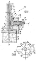
- the fixing device 10 consists of a nose 12 of axis xx 'in which slides a piston 11 moved for example under the action of the pressure of a gas from a compressor , not shown, to axially penetrate into the part 20 to be fixed on a support 30, a fastening element 21, for example a nail or a peg, coming from a supply store also not shown.
- the nose supports an arming slide 13, which is integral with it, and which comprises a striated zone 3 in which a striated zone 3 ′ of a support safety shoe 14 can be embedded according to penetration adjustment positions axial of the fixing element 21.
- the shoe 14 has a bearing surface 6 perpendicular to the axis xx 'to maintain the end of the nose 12 at an adjustment distance X from the part to be fixed.
- the penetration adjustment distance X is obtained by sliding the shoe on the slide parallel to the axis xx ′ by means of the support exerted by a lug 9 of the shoe in a slot 5 in the slide.
- the striated zones 3 and 3 ′ fit together, which secures the shoe and the slide.
- a light 4 allows the passage of the screw 17 through the shoe.
- a monobloc plate 15 for lateral positioning arranged to rotate in rotation around the screw 17 and be locked in indexed positions i, explained below, for which the plate has for each a support surface 8 substantially parallel to the axis xx ', at a distance Y from this axis.
- the positions i for indexing the bearing surfaces 8, marked 8i, here 8 1 , 8 2 , 8 3 , and with a position 8 4 d ' absence of bearing surface are materialized by recesses preferably, as here, oblong, formed on the bearing face on the shoe, marked 2 1 , 2 2 , 2 3 , 2 4 , and circularly regularly distributed around the 'axis yy' of the screw 17, or of the ring 19, which cross the plate in a hole 26.
- the positions are successively obtained by rotating the plate until embedding a boss 2 provided on the shoe in one of the recesses 2 1 , 2 2 , 2 3 , or 2 4 , which boss is held there by latching under the action of spring 18.
- the bearing surfaces 8 1 , 8 2 , 8 3 give lateral distances Y 1 , Y 2 , Y 3 different between the edge of the part to be fixed 20 or of the support part 30 and the axis xx 'of axial penetration fixing.
- a bore 25 allows the end of the spring 18 to be accommodated.
- the bore 25 ' corresponds to a symmetrical bore 25 "for housing the end of the spring 18.
- the plate is arranged to be mounted inverted on itself and is therefore reversible on the shoe to be usable on both sides.
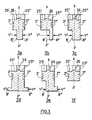
- Figures 3a, 3b, 3c, 3d, 3e thus show some possibilities for adjusting the lateral distances Y offered by the different bearing surfaces of a positioning plate turned or not.
- Figures 3d and 3e show an interesting embodiment of positioning plates, in which one of the bearing surfaces 8 'or 8 ", or both in Figure 3d are constituted by a lug (8 'or 8 ") of functional enlargement of the plate, allowing a reduction in the distance Y which can thus be smaller than the thickness of the device constituted by the nose and shoe assembly.
- Figure 3f shows the configuration of the plate of Figure 2 in half-section along a plane passing through the axis yy 'and obviously 24 for which there is no bearing surface.
- the adjusting nut 16 is unscrewed, the plate is removed from the ring 19 and the spring 18 being released from the bore 25 ′, the returned plate is put back on the ring 19, the spring is engaged 18 in the symmetrical bore 25 "of the bore 25 'and the adjusting nut 16 is screwed back.
Landscapes
- Engineering & Computer Science (AREA)
- Mechanical Engineering (AREA)
- Connection Of Plates (AREA)
- Paper (AREA)
- Footwear And Its Accessory, Manufacturing Method And Apparatuses (AREA)
- Clamps And Clips (AREA)
- Automatic Assembly (AREA)
- Load-Engaging Elements For Cranes (AREA)
- Forms Removed On Construction Sites Or Auxiliary Members Thereof (AREA)
- Processing Of Stones Or Stones Resemblance Materials (AREA)
- Spinning Or Twisting Of Yarns (AREA)
- Structure Of Telephone Exchanges (AREA)
- Supplying Of Containers To The Packaging Station (AREA)
- Portable Nailing Machines And Staplers (AREA)
Abstract
Description
- L'invention concerne les appareils de fixation, utilisés dans les travaux du bâtiment, pneumatique, à gaz ou à poudre pour propulser des éléments de fixation et ainsi fixer une pièce à fixer sur une pièce support. Plus particulièrement l'invention concerne les agrafeuses, avec lesquelles on peut par exemple fixer des panneaux d'habillage.
- Il est de plus en plus fréquent de devoir réaliser ce type de fixation de façon précise sur le support et avec une pénétration de longueur donnée.
- Pour cela, les nez des appareils de fixation actuels sont en général munis d'un sabot d'appui et d'ajustement de pénétration axiale de position réglable parallèlement à l'axe du nez permettant d'appliquer l'appareil par une surface d'appui située sur l'une de ses extrémités, sur la pièce à fixer. Mais si la fixation est ainsi rendue précise en pénétration axiale des moyens de fixation, elle reste imprécise en position latérale dans un plan perpendiculaire à l'axe du nez.
- Or cette position ne peut rester approximative lorsqu'il s'agit de fixer des pièces par leurs bords sur des supports pouvant de surcroît être de surface réduite : poutres, solives, ou autres supports couramment utilisés dans les travaux du bâtiment. Cela oblige les ouvriers utilisant ce type d'appareils à apporter plus de soin dans leurs travaux de fixation, ce qui entraîne une perte de temps.
- Par le document US 3 670 941, on connaît un appareil de fixation du type présenté ci-dessus, comportant des moyens de positionnement latéral, mais avec un seul écartement possible.
- Par le document FR 2 383 755, on connaît aussi un tel appareil, avec une vis de positionnement latéral qui exige une très grande finesse de réglage.
- La demanderesse s'est attachée à proposer un appareil de fixation du genre présenté ci-dessus, plus souple et plus simple d'emploi.
- Ainsi, la demanderesse propose un appareil de fixation du type ci-dessus, comportant un nez muni d'un sabot d'ajustement de pénétration axiale, selon l'axe du nez , des éléments de fixation, caractérisé par le fait que ledit sabot est équipé d'une plaque monobloc de positionnement latéral sur laquelle sont ménagées une pluralité de surfaces d'appui latéral distinctes sensiblement parallèle à l'axe du nez pour être appliquée notamment sur un bord d'une des pièces, support ou à fixer.
- Ainsi, les surfaces d'appui du sabot et de la plaque de positionnement forment des parties d'équerre avec lesquelles la plaque à fixer est latéralement positionnée de façon précise sans perte de temps.
- Comme la plaque de positionnement latéral est montée sur le sabot, on peut régler la pénétration sans dérégler le positionnement latéral, et inversement.
- De préférence, les surfaces d'appui latéral de la plaque de positionnement sont ménagées à des distances différentes de l'axe du nez et utilisables indépendamment les unes des autres selon le positionnement de la plaque sur le sabot.
- Avantageusement, les surfaces d'appui latéral de la plaque sont circulairement réparties sur la plaque de positionnement latéral et la plaque est montée rotative sur le sabot et maintenue sous l'action de moyens de rappel.
- Avantageusement encore, la plaque de positionnement latéral est fixée sur le sabot par indexage sur la position d'appui des surfaces d'appui de la plaque et, de préférence, l'indexation est réalisée par encliquetage.
- Avantageusement toujours, la plaque est agencée pour pouvoir être montée retournée sur elle-même sur le sabot, ce qui double le nombre des surfaces d'appui utilisables par plaque de positionnement.
- Dans une forme de réalisation intéressante de l'appareil de l'invention, il est prévu au moins un ergot d'élargissement fonctionnel de la plaque de positionnement latéral.
- L'invention sera mieux comprise à l'aide de la description suivante et du dessin l'accompagnant sur lequel :
- la figure 1 représente une coupe axiale de l'appareil de fixation selon l'invention,
- la figure 2 représente une vue en plan de la plaque de positionnement,
- les figures 3 représentent des vues en coupe de diverses surfaces d'appui possibles en position indexée.
- En référence à la figure 1, l'appareil de fixation 10 se compose d'un nez 12 d'axe xx' dans lequel coulisse un piston 11 mû par exemple sous l'action de la pression d'un gaz issu d'un compresseur, non représenté, pour faire pénétrer axialement dans la pièce 20 à fixer sur un support 30, un élément de fixation 21, par exemple un clou ou un piton, provenant d'un magasin d'alimentation également non représenté. Le nez supporte une glissière d'armement 13, qui lui est solidaire, et qui comporte une zone striée 3 dans laquelle une zone striée 3' d'un sabot 14 de sécurité d'appui peut s'encastrer selon des positions de réglage de pénétration axiale de l'élément 21 de fixation.
- A cet effet, le sabot 14 comporte une surface d'appui 6 perpendiculaire à l'axe xx' pour maintenir l'extrémité du nez 12 à une distance de réglage X de la pièce à fixer.
- La distance de réglage X de la pénétration est obtenue en faisant glisser le sabot sur la glissière parallèlement à l'axe xx' grâce au maintien qu'exerce un ergot 9 du sabot dans une lumière 5 de la glissière.
- Quand le réglage est obtenu, on serre la glissière 13 contre le sabot 14 entre la tête 7 d'une vis 17 d'axe yy' perpendiculaire à l'axe xx' et un écrou 16 dit de réglage.
- Les zones striées 3 et 3' s'encastrent, ce qui solidarise le sabot et la glissière.
- Une lumière 4 permet le passage de la vis 17 à travers le sabot.
- Ici, on insère entre le sabot et l'écrou de réglage, une plaque monobloc 15 de positionnement latéral agencée pour tourner en rotation autour de la vis 17 et être bloquée selon des positions i indexées, expliquées ci-après, pour lesquelles la plaque présente pour chacune une surface d'appui 8 sensiblement parallèle à l'axe xx', à une distance Y de cet axe.
- On insère aussi, pour compenser l'épaisseur de la plaque 15, une bague 19, emmanchée libre sur la vis, entre le sabot et l'écrou. Cette bague faisant office de butée, permet la rotation de la plaque autour de la vis, sous la seule pression d'un ressort de rappel 18 comprimé sur ladite plaque par l'écrou de réglage.
- En référence à la figure 2, qui représente la plaque 15 en plan, les position i d'indexation des surfaces d'appui 8, repérées 8i, ici 81, 82, 83, et d'une position 84 d'absence de surface d'appui sont matérialisées par des évidements de préférence, comme ici, oblongs, ménagés sur la face d'appui sur le sabot, repérées 21, 22, 23, 24, et circulairement régulièrement répartis autour de l'axe yy' de la vis 17, ou de la bague 19, qui traversent la plaque en un trou 26. Les positions sont successivement obtenues en faisant tourner la plaque jusqu'à encastrer un bossage 2 prévu sur le sabot dans l'un des évidements 21, 22, 23, ou 24, lequel bossage y est maintenu par encliquetage sous l'action du ressort 18.
- Les surfaces d'appui 81, 82, 83 donnent des distances latérales Y1, Y2, Y3 différentes entre le bord de la pièce à fixer 20 ou de la pièce support 30 et l'axe xx' de pénétration axiale de la fixation.
- Par ailleurs, un alésage 25 permet le logement de l'extrémité du ressort 18.
- En référence aux figures 3, celles repérées 3a à 3e, à chaque évidemment 2' d'indexation d'une face d'appui 8' de la plaque correspond symétriquement un évidemment 2" et une face d'appui 8" sur la face opposée de la plaque et à la surface d'appui 8' permettant de réaliser la fixation à une distance latérale Y' du bord de la pièce à fixer, correspond la surface d'appui 8" permettant de réaliser cette fixation à une distance latérale Y" différente de Y'.
- Enfin, comme montré en figure 3a, à l'alésage 25' correspond un alésage 25", symétrique, de logement de l'extrémité du ressort 18.
- Par ces moyens, la plaque est agencée pour être montée retournée sur elle-même et est donc réversible sur le sabot pour être utilisable sur ses deux faces.
- Les figures 3a, 3b, 3c, 3d, 3e, montrent ainsi quelques possibilités de réglage des distances latérales Y offertes par les différentes surfaces d'appui d'une plaque de positionnement retournée ou non.
- Notamment, les figures 3d et 3e montrent une forme de réalisation intéressante de plaques de positionnement, dans laquelle l'une des surfaces d'appui 8' ou 8", ou les deux sur la figure 3d sont constituées par un ergot (8' ou 8") d'élargissement fonctionnel de la plaque, permettant une diminution de la distance Y qui peut ainsi être plus petite que l'épaisseur de l'appareil constituée par l'ensemble nez et sabot.
- Enfin, la figure 3f montre la configuration de la plaque de la figure 2 en demi-coupe selon un plan passant par l'axe yy' et l'évidemment 24 pour lequel il n'y a pas de surface d'appui.
- Le réglage de l'appareil de fixation en positionnement axial et latéral est obtenu en réalisant les opérations suivantes :
- 1) on dévisse l'écrou de réglage 16,
- 2) on fait glisser le sabot 14 sur la glissière d'armement 13 sur une position X correspondant à une pénétration axiale souhaitée du moyen de fixation 21,
- 3) on serre l'écrou 16 sur la bague 19 pour encastrer les zones de stries 3, 3' et ainsi fixer le sabot sur la glissière,
- 4) on fait tourner la plaque 15 autour de la vis 17 de façon à mettre en position la surface d'appui 8 donnant la distance Y latérale désirée. La position est atteinte quand le bossage 2 est encliqueté dans l'un des évidements 21, 22, 23 ou 24 correspondant à la surface d'appui latéralement distante de Y1, Y2, Y3 ou Y4 de l'axe xx' du nez de l'appareil.
- Pour retourner la plaque 15, on dévisse l'écrou de réglage 16, on retire la plaque de la bague 19 et le ressort 18 étant dégagé de l'alésage 25', on remet la plaque retournée sur la bague 19, on engage le ressort 18 dans l'alésage symétrique 25" de l'alésage 25' et on revisse l'écrou de réglage 16.
Claims (8)
- Appareil de fixation pneumatique, à gaz ou à poudre pour propulser des éléments de fixation (21) et ainsi fixer une pièce (20) à fixer sur une pièce support, comportant un nez (12) muni d'un sabot d'appui (14), caractérisé par le fait que ledit sabot est équipé d'une plaque monobloc (15) de positionnement latéral sur laquelle sont ménagées une pluralité de surfaces (8, 8', 8", 81, 82, 83) d'appui latéral distinctes sensiblement parallèle à l'axe du nez pour être appliquée notamment sur un bord d'une des pièces, support ou à fixer.
- Appareil de fixation selon la revendication 1, dans lequel les surfaces d'appui (8, 8', 8 ") latéral de la plaque (15) de positionnement sont ménagées à des distances (Y, Y', Y") différentes de l'axe du nez.
- Appareil de fixation selon la revendication 2, dans lequel les surfaces d'appui latéral de la plaque sont circulairement réparties (81, 82, 83) sur la plaque de positionnement latéral, la plaque étant montée rotative et maintenue sous l'action de moyens de rappel (16, 17, 18).
- Appareil de fixation selon l'une des revendications 2 et 3, dans lequel la plaque de positionnement latéral est fixée sur le sabot par indexage (2, 2', 2",21, 22, 23, 24) sur la position d'appui des surfaces d'appui de la plaque.
- Appareil de fixation selon la revendication 4, dans lequel l'indexation est réalisée par encliquetage (18, 2, 2').
- Appareil de fixation selon l'une quelconque des revendications précédentes, dans lequel la plaque est agencée pour pouvoir être montée retournée sur elle-même (25', 25", Y', Y", 2', 2") sur le sabot.
- Appareil de fixation selon l'une quelconque des revendications précédentes, dans lequel (3d, 3e) il est prévu au moins un ergot (8', 8") d'élargissement fonctionnel de la plaque de positionnement latéral.
- Appareil de fixation selon l'une des revendications 1 à 7, dans lequel le sabot d'appui (14) est un sabot d'ajustement de pénétration axiale, selon l'axe x, x' du nez, des éléments de fixation.
Applications Claiming Priority (2)
| Application Number | Priority Date | Filing Date | Title |
|---|---|---|---|
| FR0300723A FR2850314B1 (fr) | 2003-01-23 | 2003-01-23 | Appareil de fixation a sabot d'appui et plaque de positionnement |
| FR0300723 | 2003-01-23 |
Publications (2)
| Publication Number | Publication Date |
|---|---|
| EP1459852A1 true EP1459852A1 (fr) | 2004-09-22 |
| EP1459852B1 EP1459852B1 (fr) | 2010-06-02 |
Family
ID=32669162
Family Applications (1)
| Application Number | Title | Priority Date | Filing Date |
|---|---|---|---|
| EP04290144A Expired - Lifetime EP1459852B1 (fr) | 2003-01-23 | 2004-01-20 | Appareil de fixation à sabot d'appui et plaque de positionnement |
Country Status (10)
| Country | Link |
|---|---|
| US (1) | US7051914B2 (fr) |
| EP (1) | EP1459852B1 (fr) |
| CN (1) | CN100381256C (fr) |
| AT (1) | ATE469735T1 (fr) |
| AU (1) | AU2004200205B2 (fr) |
| CA (1) | CA2455379C (fr) |
| DE (1) | DE602004027430D1 (fr) |
| FR (1) | FR2850314B1 (fr) |
| NZ (1) | NZ530753A (fr) |
| TW (1) | TWI247081B (fr) |
Families Citing this family (10)
| Publication number | Priority date | Publication date | Assignee | Title |
|---|---|---|---|---|
| WO2007082136A2 (fr) * | 2006-01-05 | 2007-07-19 | Illinois Tool Works Inc. | Adaptateur ajustable a 45 degres pour cloueur de plancher |
| US20070215668A1 (en) * | 2006-03-03 | 2007-09-20 | Jerry Tabacco | Nail gun siding installation guide |
| US7344057B2 (en) * | 2006-05-02 | 2008-03-18 | Laboratoire Primatech Inc. | Nailer with adjustable guide member |
| US8056785B2 (en) * | 2007-10-15 | 2011-11-15 | Illinois Tool Works Inc. | Moveable fastening tool holding bracket |
| US8235270B2 (en) * | 2007-10-15 | 2012-08-07 | Illinois Tool Works Inc. | Fastening tool holding bracket |
| US8387846B2 (en) | 2009-06-08 | 2013-03-05 | Illinois Tool Works Inc | Fastening tool with blind guide work contact tip |
| CN102767577B (zh) * | 2012-07-11 | 2015-04-01 | 南京冠盛汽配有限公司 | 低震动自动滑移补偿复式花键万向节 |
| US10265840B2 (en) | 2014-11-10 | 2019-04-23 | Powernail Company | Adjustable fastener-driving tool support system |
| GB2580111B (en) * | 2018-12-21 | 2021-04-28 | Caterpillar Energy Solutions Gmbh | Device for tensioning a connecting element |
| USD1042102S1 (en) * | 2022-12-06 | 2024-09-17 | Vander Gore | Nail gun stabilizer |
Citations (5)
| Publication number | Priority date | Publication date | Assignee | Title |
|---|---|---|---|---|
| US3670941A (en) | 1970-03-02 | 1972-06-20 | Fred I Grinnell | Retractable guard and guide for nailer |
| FR2383755A1 (fr) | 1977-03-14 | 1978-10-13 | Fesquet Amedee | Dispositif de cloutage |
| US5261588A (en) | 1992-05-22 | 1993-11-16 | Joseph Lin | Improvement for a nailing gun |
| DE9420286U1 (de) * | 1994-12-19 | 1995-03-09 | Erwin Müller GmbH & Co, 49808 Lingen | Randanschlagschieber |
| GB2375075A (en) * | 2001-05-03 | 2002-11-06 | Denis Whittaker | A router tiltably mounted on a base |
Family Cites Families (15)
| Publication number | Priority date | Publication date | Assignee | Title |
|---|---|---|---|---|
| US2915754A (en) * | 1957-05-15 | 1959-12-08 | Fastener Corp | Fastener driving apparatus |
| US3107556A (en) * | 1961-05-11 | 1963-10-22 | Lawrence E Pugsley | Drill and guide therefor |
| US3822817A (en) * | 1972-05-22 | 1974-07-09 | K Umphress | Semi-automatic gun mount |
| US4290464A (en) * | 1980-03-20 | 1981-09-22 | Mario Marsan | Holder for portable electric cutting instrument |
| DE3343683A1 (de) * | 1983-12-02 | 1985-06-13 | Robert 5446 Engeln Wolff | Bohr- und fraesfuehrer fuer auswechselbare antriebsmaschinen |
| US4655653A (en) * | 1984-09-19 | 1987-04-07 | Robert J. Hall | Routers |
| US4729698A (en) * | 1986-09-05 | 1988-03-08 | Haddon Jesse E | Multi-purpose and versatile portable power tool |
| US4821938A (en) * | 1987-11-25 | 1989-04-18 | Haytayan Harry M | Powder-actuated fastener driving tool |
| US5006022A (en) * | 1989-05-02 | 1991-04-09 | Bernard Miller | Axially movable tool and guide |
| US5054678A (en) * | 1989-07-17 | 1991-10-08 | Duo-Fast Corporation | Furniture clip/tool |
| US5150993A (en) * | 1992-01-30 | 1992-09-29 | Bernard Miller | Pivot assembly for tool guide |
| US5346065A (en) | 1993-02-11 | 1994-09-13 | Minnesota Mining And Manufacturing Company | Media shipping container |
| CA2339296C (fr) * | 2000-03-03 | 2006-05-09 | John Dickhaut | Dispositif de fixation pour pistolet agrafeur ou pistolet cloueur |
| US6988648B2 (en) * | 2001-03-01 | 2006-01-24 | Illinois Tool Works Inc. | Adjustable depth of drive device |
| CN1235722C (zh) * | 2001-06-07 | 2006-01-11 | 周淑慧 | 二维定位打钉枪 |
-
2003
- 2003-01-23 FR FR0300723A patent/FR2850314B1/fr not_active Expired - Fee Related
-
2004
- 2004-01-15 TW TW093101083A patent/TWI247081B/zh not_active IP Right Cessation
- 2004-01-19 AU AU2004200205A patent/AU2004200205B2/en not_active Ceased
- 2004-01-19 CA CA002455379A patent/CA2455379C/fr not_active Expired - Fee Related
- 2004-01-20 AT AT04290144T patent/ATE469735T1/de not_active IP Right Cessation
- 2004-01-20 DE DE602004027430T patent/DE602004027430D1/de not_active Expired - Lifetime
- 2004-01-20 CN CNB2004100024498A patent/CN100381256C/zh not_active Expired - Fee Related
- 2004-01-20 EP EP04290144A patent/EP1459852B1/fr not_active Expired - Lifetime
- 2004-01-22 NZ NZ530753A patent/NZ530753A/en not_active IP Right Cessation
- 2004-01-23 US US10/762,554 patent/US7051914B2/en not_active Expired - Lifetime
Patent Citations (5)
| Publication number | Priority date | Publication date | Assignee | Title |
|---|---|---|---|---|
| US3670941A (en) | 1970-03-02 | 1972-06-20 | Fred I Grinnell | Retractable guard and guide for nailer |
| FR2383755A1 (fr) | 1977-03-14 | 1978-10-13 | Fesquet Amedee | Dispositif de cloutage |
| US5261588A (en) | 1992-05-22 | 1993-11-16 | Joseph Lin | Improvement for a nailing gun |
| DE9420286U1 (de) * | 1994-12-19 | 1995-03-09 | Erwin Müller GmbH & Co, 49808 Lingen | Randanschlagschieber |
| GB2375075A (en) * | 2001-05-03 | 2002-11-06 | Denis Whittaker | A router tiltably mounted on a base |
Also Published As
| Publication number | Publication date |
|---|---|
| AU2004200205A1 (en) | 2004-08-12 |
| TW200417698A (en) | 2004-09-16 |
| CN100381256C (zh) | 2008-04-16 |
| AU2004200205B2 (en) | 2006-09-14 |
| US20040188493A1 (en) | 2004-09-30 |
| US7051914B2 (en) | 2006-05-30 |
| CA2455379C (fr) | 2007-08-28 |
| CN1517183A (zh) | 2004-08-04 |
| FR2850314A1 (fr) | 2004-07-30 |
| TWI247081B (en) | 2006-01-11 |
| FR2850314B1 (fr) | 2006-06-23 |
| NZ530753A (en) | 2004-11-26 |
| EP1459852B1 (fr) | 2010-06-02 |
| CA2455379A1 (fr) | 2004-07-23 |
| ATE469735T1 (de) | 2010-06-15 |
| DE602004027430D1 (de) | 2010-07-15 |
Similar Documents
| Publication | Publication Date | Title |
|---|---|---|
| EP1459852A1 (fr) | Appareil de fixation à sabot d'appui et plaque de positionnement | |
| EP1411401A1 (fr) | Couronne à vis pour pièce d'horlogerie | |
| FR2700053A1 (fr) | Nouvelle ligature pour bec d'instrument à vent. | |
| EP1486294A1 (fr) | Perche de télé actionnement d'un outil à main | |
| WO2010004470A1 (fr) | Systeme a contacts electriques integres | |
| FR2487711A1 (fr) | Dispositif de fixation d'un foret a un outil mecanique et adaptateur utilise dans ce dispositif | |
| EP3090850A1 (fr) | Moyen de fixation de lames de revêtement de surface | |
| WO1999019598A1 (fr) | Accouplement pour dispositif a transmission de forces | |
| EP2865426B1 (fr) | Système de fixation de prise d'escalade, prise d'escalade comprenant un tel système et mur d'escalade comprenant une telle prise | |
| FR2795013A1 (fr) | Outil de centrage et de serrage | |
| FR2607559A1 (fr) | Systeme d'assemblage de panneaux en des positions angulaires variees, et panneaux adaptes a l'utilisation de ce systeme | |
| EP0032476A2 (fr) | Etau à plusieurs capacités d'ouverture maximum et à effets de serrage multiples | |
| FR3006168A1 (fr) | Cale osseuse distratante | |
| FR2972342A1 (fr) | Dispositif pour relier un arc orthodontique avec une dent | |
| FR2765115A1 (fr) | Fixation de securite de chaussure de ski | |
| EP0227511A1 (fr) | Dispositif de serrage d'au moins deux pièces accolées à assembler, et ensemble de serrage comprenant un outil de serrage et ledit dispositif de serrage | |
| EP1345001B1 (fr) | Carabine à canon amovible | |
| EP0234171B1 (fr) | Tête d'alésage | |
| FR2928568A1 (fr) | Outil d'usinage et patin de guidage amortisseur d'outils d'usinage | |
| WO2013150219A1 (fr) | Dispositif d'assemblage demontable pour elements de profile | |
| FR2791767A1 (fr) | Crosse de fusil a busc reglable et fusil equipe d'une telle crosse | |
| EP3827925B1 (fr) | Pince à embouts interchangeables | |
| CH687681A5 (fr) | Machine à fraiser des rainures. | |
| CH686345A5 (en) | Axial or radial cutting tool | |
| FR2784320A1 (fr) | Dispositif de positionnement d'un corps par rapport a son support et notamment du corps d'une electro-broche par rapport a son support |
Legal Events
| Date | Code | Title | Description |
|---|---|---|---|
| PUAI | Public reference made under article 153(3) epc to a published international application that has entered the european phase |
Free format text: ORIGINAL CODE: 0009012 |
|
| AK | Designated contracting states |
Kind code of ref document: A1 Designated state(s): AT BE BG CH CY CZ DE DK EE ES FI FR GB GR HU IE IT LI LU MC NL PT RO SE SI SK TR |
|
| AX | Request for extension of the european patent |
Extension state: AL LT LV MK |
|
| 17P | Request for examination filed |
Effective date: 20050318 |
|
| AKX | Designation fees paid |
Designated state(s): AT BE BG CH CY CZ DE DK EE ES FI FR GB GR HU IE IT LI LU MC NL PT RO SE SI SK TR |
|
| 17Q | First examination report despatched |
Effective date: 20070420 |
|
| GRAP | Despatch of communication of intention to grant a patent |
Free format text: ORIGINAL CODE: EPIDOSNIGR1 |
|
| GRAS | Grant fee paid |
Free format text: ORIGINAL CODE: EPIDOSNIGR3 |
|
| GRAA | (expected) grant |
Free format text: ORIGINAL CODE: 0009210 |
|
| AK | Designated contracting states |
Kind code of ref document: B1 Designated state(s): AT BE BG CH CY CZ DE DK EE ES FI FR GB GR HU IE IT LI LU MC NL PT RO SE SI SK TR |
|
| REG | Reference to a national code |
Ref country code: GB Ref legal event code: FG4D Free format text: NOT ENGLISH |
|
| REG | Reference to a national code |
Ref country code: CH Ref legal event code: EP |
|
| REG | Reference to a national code |
Ref country code: IE Ref legal event code: FG4D Free format text: LANGUAGE OF EP DOCUMENT: FRENCH |
|
| REF | Corresponds to: |
Ref document number: 602004027430 Country of ref document: DE Date of ref document: 20100715 Kind code of ref document: P |
|
| REG | Reference to a national code |
Ref country code: NL Ref legal event code: VDEP Effective date: 20100602 |
|
| PG25 | Lapsed in a contracting state [announced via postgrant information from national office to epo] |
Ref country code: SE Free format text: LAPSE BECAUSE OF FAILURE TO SUBMIT A TRANSLATION OF THE DESCRIPTION OR TO PAY THE FEE WITHIN THE PRESCRIBED TIME-LIMIT Effective date: 20100602 |
|
| PG25 | Lapsed in a contracting state [announced via postgrant information from national office to epo] |
Ref country code: AT Free format text: LAPSE BECAUSE OF FAILURE TO SUBMIT A TRANSLATION OF THE DESCRIPTION OR TO PAY THE FEE WITHIN THE PRESCRIBED TIME-LIMIT Effective date: 20100602 Ref country code: FI Free format text: LAPSE BECAUSE OF FAILURE TO SUBMIT A TRANSLATION OF THE DESCRIPTION OR TO PAY THE FEE WITHIN THE PRESCRIBED TIME-LIMIT Effective date: 20100602 Ref country code: SI Free format text: LAPSE BECAUSE OF FAILURE TO SUBMIT A TRANSLATION OF THE DESCRIPTION OR TO PAY THE FEE WITHIN THE PRESCRIBED TIME-LIMIT Effective date: 20100602 |
|
| PG25 | Lapsed in a contracting state [announced via postgrant information from national office to epo] |
Ref country code: GR Free format text: LAPSE BECAUSE OF FAILURE TO SUBMIT A TRANSLATION OF THE DESCRIPTION OR TO PAY THE FEE WITHIN THE PRESCRIBED TIME-LIMIT Effective date: 20100903 Ref country code: CY Free format text: LAPSE BECAUSE OF FAILURE TO SUBMIT A TRANSLATION OF THE DESCRIPTION OR TO PAY THE FEE WITHIN THE PRESCRIBED TIME-LIMIT Effective date: 20100602 |
|
| REG | Reference to a national code |
Ref country code: IE Ref legal event code: FD4D |
|
| PG25 | Lapsed in a contracting state [announced via postgrant information from national office to epo] |
Ref country code: IE Free format text: LAPSE BECAUSE OF FAILURE TO SUBMIT A TRANSLATION OF THE DESCRIPTION OR TO PAY THE FEE WITHIN THE PRESCRIBED TIME-LIMIT Effective date: 20100602 Ref country code: NL Free format text: LAPSE BECAUSE OF FAILURE TO SUBMIT A TRANSLATION OF THE DESCRIPTION OR TO PAY THE FEE WITHIN THE PRESCRIBED TIME-LIMIT Effective date: 20100602 Ref country code: EE Free format text: LAPSE BECAUSE OF FAILURE TO SUBMIT A TRANSLATION OF THE DESCRIPTION OR TO PAY THE FEE WITHIN THE PRESCRIBED TIME-LIMIT Effective date: 20100602 |
|
| PG25 | Lapsed in a contracting state [announced via postgrant information from national office to epo] |
Ref country code: CZ Free format text: LAPSE BECAUSE OF FAILURE TO SUBMIT A TRANSLATION OF THE DESCRIPTION OR TO PAY THE FEE WITHIN THE PRESCRIBED TIME-LIMIT Effective date: 20100602 Ref country code: SK Free format text: LAPSE BECAUSE OF FAILURE TO SUBMIT A TRANSLATION OF THE DESCRIPTION OR TO PAY THE FEE WITHIN THE PRESCRIBED TIME-LIMIT Effective date: 20100602 Ref country code: RO Free format text: LAPSE BECAUSE OF FAILURE TO SUBMIT A TRANSLATION OF THE DESCRIPTION OR TO PAY THE FEE WITHIN THE PRESCRIBED TIME-LIMIT Effective date: 20100602 Ref country code: PT Free format text: LAPSE BECAUSE OF FAILURE TO SUBMIT A TRANSLATION OF THE DESCRIPTION OR TO PAY THE FEE WITHIN THE PRESCRIBED TIME-LIMIT Effective date: 20101004 |
|
| PG25 | Lapsed in a contracting state [announced via postgrant information from national office to epo] |
Ref country code: IT Free format text: LAPSE BECAUSE OF FAILURE TO SUBMIT A TRANSLATION OF THE DESCRIPTION OR TO PAY THE FEE WITHIN THE PRESCRIBED TIME-LIMIT Effective date: 20100602 |
|
| PLBE | No opposition filed within time limit |
Free format text: ORIGINAL CODE: 0009261 |
|
| STAA | Information on the status of an ep patent application or granted ep patent |
Free format text: STATUS: NO OPPOSITION FILED WITHIN TIME LIMIT |
|
| PG25 | Lapsed in a contracting state [announced via postgrant information from national office to epo] |
Ref country code: DK Free format text: LAPSE BECAUSE OF FAILURE TO SUBMIT A TRANSLATION OF THE DESCRIPTION OR TO PAY THE FEE WITHIN THE PRESCRIBED TIME-LIMIT Effective date: 20100602 |
|
| 26N | No opposition filed |
Effective date: 20110303 |
|
| REG | Reference to a national code |
Ref country code: DE Ref legal event code: R097 Ref document number: 602004027430 Country of ref document: DE Effective date: 20110302 |
|
| BERE | Be: lapsed |
Owner name: SOC. DE PROSPECTION ET D'INVENTIONS TECHNIQUES SP Effective date: 20110131 |
|
| PG25 | Lapsed in a contracting state [announced via postgrant information from national office to epo] |
Ref country code: MC Free format text: LAPSE BECAUSE OF NON-PAYMENT OF DUE FEES Effective date: 20110131 |
|
| REG | Reference to a national code |
Ref country code: CH Ref legal event code: PL |
|
| PG25 | Lapsed in a contracting state [announced via postgrant information from national office to epo] |
Ref country code: CH Free format text: LAPSE BECAUSE OF NON-PAYMENT OF DUE FEES Effective date: 20110131 Ref country code: LI Free format text: LAPSE BECAUSE OF NON-PAYMENT OF DUE FEES Effective date: 20110131 |
|
| PG25 | Lapsed in a contracting state [announced via postgrant information from national office to epo] |
Ref country code: BE Free format text: LAPSE BECAUSE OF NON-PAYMENT OF DUE FEES Effective date: 20110131 |
|
| PGFP | Annual fee paid to national office [announced via postgrant information from national office to epo] |
Ref country code: DE Payment date: 20130129 Year of fee payment: 10 Ref country code: GB Payment date: 20130125 Year of fee payment: 10 Ref country code: FR Payment date: 20130211 Year of fee payment: 10 |
|
| PG25 | Lapsed in a contracting state [announced via postgrant information from national office to epo] |
Ref country code: LU Free format text: LAPSE BECAUSE OF NON-PAYMENT OF DUE FEES Effective date: 20110120 |
|
| PG25 | Lapsed in a contracting state [announced via postgrant information from national office to epo] |
Ref country code: TR Free format text: LAPSE BECAUSE OF FAILURE TO SUBMIT A TRANSLATION OF THE DESCRIPTION OR TO PAY THE FEE WITHIN THE PRESCRIBED TIME-LIMIT Effective date: 20100602 Ref country code: BG Free format text: LAPSE BECAUSE OF FAILURE TO SUBMIT A TRANSLATION OF THE DESCRIPTION OR TO PAY THE FEE WITHIN THE PRESCRIBED TIME-LIMIT Effective date: 20100902 |
|
| PG25 | Lapsed in a contracting state [announced via postgrant information from national office to epo] |
Ref country code: HU Free format text: LAPSE BECAUSE OF FAILURE TO SUBMIT A TRANSLATION OF THE DESCRIPTION OR TO PAY THE FEE WITHIN THE PRESCRIBED TIME-LIMIT Effective date: 20100602 Ref country code: ES Free format text: LAPSE BECAUSE OF FAILURE TO SUBMIT A TRANSLATION OF THE DESCRIPTION OR TO PAY THE FEE WITHIN THE PRESCRIBED TIME-LIMIT Effective date: 20100913 |
|
| REG | Reference to a national code |
Ref country code: DE Ref legal event code: R119 Ref document number: 602004027430 Country of ref document: DE |
|
| GBPC | Gb: european patent ceased through non-payment of renewal fee |
Effective date: 20140120 |
|
| PG25 | Lapsed in a contracting state [announced via postgrant information from national office to epo] |
Ref country code: DE Free format text: LAPSE BECAUSE OF NON-PAYMENT OF DUE FEES Effective date: 20140801 |
|
| REG | Reference to a national code |
Ref country code: FR Ref legal event code: ST Effective date: 20140930 |
|
| REG | Reference to a national code |
Ref country code: DE Ref legal event code: R119 Ref document number: 602004027430 Country of ref document: DE Effective date: 20140801 |
|
| PG25 | Lapsed in a contracting state [announced via postgrant information from national office to epo] |
Ref country code: FR Free format text: LAPSE BECAUSE OF NON-PAYMENT OF DUE FEES Effective date: 20140131 Ref country code: GB Free format text: LAPSE BECAUSE OF NON-PAYMENT OF DUE FEES Effective date: 20140120 |