EP1460209A2 - Kombinationsschlösser - Google Patents
Kombinationsschlösser Download PDFInfo
- Publication number
- EP1460209A2 EP1460209A2 EP03257066A EP03257066A EP1460209A2 EP 1460209 A2 EP1460209 A2 EP 1460209A2 EP 03257066 A EP03257066 A EP 03257066A EP 03257066 A EP03257066 A EP 03257066A EP 1460209 A2 EP1460209 A2 EP 1460209A2
- Authority
- EP
- European Patent Office
- Prior art keywords
- shackle
- long leg
- combination lock
- tumbler
- dial
- Prior art date
- Legal status (The legal status is an assumption and is not a legal conclusion. Google has not performed a legal analysis and makes no representation as to the accuracy of the status listed.)
- Withdrawn
Links
Images




Classifications
-
- E—FIXED CONSTRUCTIONS
- E05—LOCKS; KEYS; WINDOW OR DOOR FITTINGS; SAFES
- E05B—LOCKS; ACCESSORIES THEREFOR; HANDCUFFS
- E05B37/00—Permutation or combination locks; Puzzle locks
- E05B37/02—Permutation or combination locks; Puzzle locks with tumbler discs or rings arranged on a single axis, each disc being adjustable independently of the others
- E05B37/025—Permutation or combination locks; Puzzle locks with tumbler discs or rings arranged on a single axis, each disc being adjustable independently of the others in padlocks
-
- E—FIXED CONSTRUCTIONS
- E05—LOCKS; KEYS; WINDOW OR DOOR FITTINGS; SAFES
- E05B—LOCKS; ACCESSORIES THEREFOR; HANDCUFFS
- E05B37/00—Permutation or combination locks; Puzzle locks
- E05B37/0003—Permutation or combination locks; Puzzle locks preventing detection of the combination
- E05B37/001—Permutation or combination locks; Puzzle locks preventing detection of the combination through listening or feeling
- E05B37/0017—Permutation or combination locks; Puzzle locks preventing detection of the combination through listening or feeling by producing false clicks; by use of false gates
-
- E—FIXED CONSTRUCTIONS
- E05—LOCKS; KEYS; WINDOW OR DOOR FITTINGS; SAFES
- E05B—LOCKS; ACCESSORIES THEREFOR; HANDCUFFS
- E05B67/00—Padlocks; Details thereof
- E05B67/06—Shackles; Arrangement of the shackle
- E05B67/22—Padlocks with sliding shackles, with or without rotary or pivotal movement
-
- E—FIXED CONSTRUCTIONS
- E05—LOCKS; KEYS; WINDOW OR DOOR FITTINGS; SAFES
- E05B—LOCKS; ACCESSORIES THEREFOR; HANDCUFFS
- E05B37/00—Permutation or combination locks; Puzzle locks
- E05B37/0048—Permutation or combination locks; Puzzle locks with changeable combination
- E05B37/0058—Permutation or combination locks; Puzzle locks with changeable combination by axial disengagement between hub and rim of tumbler discs or rings
-
- Y—GENERAL TAGGING OF NEW TECHNOLOGICAL DEVELOPMENTS; GENERAL TAGGING OF CROSS-SECTIONAL TECHNOLOGIES SPANNING OVER SEVERAL SECTIONS OF THE IPC; TECHNICAL SUBJECTS COVERED BY FORMER USPC CROSS-REFERENCE ART COLLECTIONS [XRACs] AND DIGESTS
- Y10—TECHNICAL SUBJECTS COVERED BY FORMER USPC
- Y10T—TECHNICAL SUBJECTS COVERED BY FORMER US CLASSIFICATION
- Y10T70/00—Locks
- Y10T70/40—Portable
- Y10T70/413—Padlocks
- Y10T70/417—Combination-controlled
-
- Y—GENERAL TAGGING OF NEW TECHNOLOGICAL DEVELOPMENTS; GENERAL TAGGING OF CROSS-SECTIONAL TECHNOLOGIES SPANNING OVER SEVERAL SECTIONS OF THE IPC; TECHNICAL SUBJECTS COVERED BY FORMER USPC CROSS-REFERENCE ART COLLECTIONS [XRACs] AND DIGESTS
- Y10—TECHNICAL SUBJECTS COVERED BY FORMER USPC
- Y10T—TECHNICAL SUBJECTS COVERED BY FORMER US CLASSIFICATION
- Y10T70/00—Locks
- Y10T70/40—Portable
- Y10T70/413—Padlocks
- Y10T70/417—Combination-controlled
- Y10T70/422—Rigid shackle
- Y10T70/424—Sliding
-
- Y—GENERAL TAGGING OF NEW TECHNOLOGICAL DEVELOPMENTS; GENERAL TAGGING OF CROSS-SECTIONAL TECHNOLOGIES SPANNING OVER SEVERAL SECTIONS OF THE IPC; TECHNICAL SUBJECTS COVERED BY FORMER USPC CROSS-REFERENCE ART COLLECTIONS [XRACs] AND DIGESTS
- Y10—TECHNICAL SUBJECTS COVERED BY FORMER USPC
- Y10T—TECHNICAL SUBJECTS COVERED BY FORMER US CLASSIFICATION
- Y10T70/00—Locks
- Y10T70/70—Operating mechanism
- Y10T70/7153—Combination
- Y10T70/7181—Tumbler type
- Y10T70/7198—Single tumbler set
- Y10T70/7237—Rotary or swinging tumblers
- Y10T70/726—Individually set
- Y10T70/7305—Manually operable
-
- Y—GENERAL TAGGING OF NEW TECHNOLOGICAL DEVELOPMENTS; GENERAL TAGGING OF CROSS-SECTIONAL TECHNOLOGIES SPANNING OVER SEVERAL SECTIONS OF THE IPC; TECHNICAL SUBJECTS COVERED BY FORMER USPC CROSS-REFERENCE ART COLLECTIONS [XRACs] AND DIGESTS
- Y10—TECHNICAL SUBJECTS COVERED BY FORMER USPC
- Y10T—TECHNICAL SUBJECTS COVERED BY FORMER US CLASSIFICATION
- Y10T70/00—Locks
- Y10T70/70—Operating mechanism
- Y10T70/7153—Combination
- Y10T70/7322—Permutation
Definitions
- This invention relates to combination locks, and, more particularly, to combination locks constructed to virtually eliminate unwanted changes to the pre-set combination.
- combination lock which employs a plurality of rotatable independent dials, each of which forms one of the indicia, usually numerals or letters, comprising the combination for releasing the lock.
- a further problem, which has consistently annoyed the user and caused the user to incur substantial problems is the ability of many prior art combination locks to enter a combination re-setting mode, without the user's knowledge. As a result, consumers are often unable to open a lock or cannot use the lock since the desired combination had been altered without their knowledge.
- Another object of the present invention is to provide a combination lock having the characteristic features described above which employs a minimum of components and is quickly and easily assembled, thereby providing a lock capable of being constructed at a competitive price.
- Another object of the present invention is to provide a combination lock construction having the characteristic features described above which effectively seals the rotating components from external contamination and effectively prevents any external contaminants from reaching the rotating components thereof.
- Another object of the present invention is to provide a combination lock construction having the characteristic features described above which prevents the combination for the lock from being accidentally changed or altered without the user's complete knowledge.
- the lock construction of the present invention is constructed with the interior chambers thereof virtually sealed from ambient surroundings, thereby preventing unwanted contamination from entering the interior of the lock and the rotating components thereof. In this way, the prior art degradation and interference of the lock operation by contamination is virtually eliminated.
- a minimum number of components are employed in combination with a housing and a movable shackle in r order to provide the desired, unique combination lock construction of this invention.
- a plurality of rotating dials and a plurality of tumbler sleeves are required to provide the desired locking mechanism.
- four dials and tumbler sleeves are employed with the housing.
- the ability of unauthorized persons to determine the actual combination using the sound is thwarted by incorporating in the housing a plurality of false void zones having a construction similar to the actual open chamber or open zone which provides the lock release for each tumbler.
- the central housing of the combination lock of this invention incorporates an elongated lock release groove or slot which provides the lock release zone for each of the independent rotatable tumbler sleeves.
- the housing also incorporates a plurality of non-releasing open zones or slots formed in association with the lock release groove for each rotatable tumbler sleeve. In this way, the desired false click is provided for each rotatable dial in order to thwart unwanted opening of the combination lock of this invention.
- all of the rotatable components are mounted in a single elongated bore formed in the housing and a sealing cap is employed to effectively close and seal the elongated bore once the components are mounted therein.
- a sealing cap is employed to effectively close and seal the elongated bore once the components are mounted therein.
- the present invention achieves a combination r lock using a minimum number of independent components each of which is capable of being quickly assembled into the final product.
- a construction is attained which is capable of being manufactured at a competitive price, while providing a high quality, highly effective combination lock which prevents exposure to environmental contamination and also incorporates means for virtually eliminating unauthorized persons from opening the lock without knowledge of the combination.
- the combination lock of the present invention incorporates a shackle holding assembly comprising a holding member or a sleeve or bowl which is mounted to the free end of the elongated leg of the shackle, with the sleeve/bowl incorporating a radially extending outer rim.
- spring means are mounted in cooperating relationship with the rim of the sleeve/bowl, with the spring means being maintained under compression between the sleeve/bowl and a bottom surface of the housing of the combination lock.
- a plug member is employed for forming the cooperating contact surface on which the spring means is maintained. In this way, ease of assembly is attained with a minimum of components being employed.
- the combination is changed by axially moving the long leg of the shackle downwardly towards the base or bottom of the lock housing in order to release the tumblers and allow the indicia bearing dials to freely rotate.
- axial movement of the shackle has occurred without the knowledge of the user, with the dials being rotated to a new combination, completely unknown to the user.
- the spring force is constantly acting upon the rim of the sleeve/bowl which is engaged with the terminating end of the long leg of the shackle. As a result, unwanted axial movement of the shackle is prevented.
- the user Whenever a user wishes to alter the combination of the lock, the user must exert an activation force on the long leg of the shackle in order to axially move the shackle against the spring force. Only by providing an activation force r to the shackle is the shackle leg able to move axially downwardly.
- the indicia bearing wheels are forced to move, thereby allowing this use to change the combination to a new setting.
- the activation force is removed and the spring force causes the sleeve/bowl and shackle to be returned to their original positions.
- the spring means and the sleeve/bowl continue to biasingly maintain the shackle in this raised position, providing assurance that the newly set combination cannot be altered or changed accidentally.
- the invention accordingly comprises an article of manufacture possessing the features, properties, and the relation of elements which will be exemplified in the article hereinafter described and the scope of the invention will be indicated in the claims.
- combination lock 20 of the present invention can best be understood.
- the preferred embodiment of the present invention is fully disclosed.
- the present invention can be implemented using alternate constructions, which alternate constructions are intended to be within the scope of the present invention.
- combination lock 20 of the present invention is constructed using a minimum of principal components, thereby substantially reducing the complexity found in most prior art combination locks.
- the present invention provides a highly effective, commercially desirable construction capable of being produced at a competitive cost, while still providing all of the locking and theft deterrent features typically incorporated in prior r art combination locks.
- the principal components comprise a central housing 21, a shackle 22, four separate and independent tumbler sleeve 23, and four separate and independent rotatable dials 24.
- Each tumbler sleeve 23 comprises a generally cylindrical shape incorporating a single locking fin 25 radially extending from outer, circular-shaped surface 26.
- each tumbler sleeve 23 also comprises an inside, circular-shaped surface 27 which is coaxially aligned with outside surface 26. The diameter of inside surface 27 of tumbler sleeve 23 is constructed to enable each tumbler sleeve 23 to freely pivot about the outer surface of shackle 22.
- Each dial 24 is constructed for peripherally surrounding and cooperating with a tumbler sleeve 23.
- each dial 24 comprises two separate and distinct, circular-shaped inside surfaces 28 and 29.
- side surface 28 comprises a diameter slightly greater than the diameter of outside surface 26 of tumbler sleeve 23, in order to enable tumbler sleeve 23 and dial 24 to cooperate with each other while being independently rotationally movable about shackle 22.
- each dial 24 comprises a plurality of slots 30 formed in inside surface 28, with each slot being constructed for receiving and retaining radially extending fin 25 of tumbler sleeve 23. In this way, whenever radially extending fin 25 is mounted in a slot 30 of dial 24, tumbler sleeve 23 and dial 24 are in interlocked engagement, causing both members to rotate together about shackle 22.
- the number of slots 30 formed in dial 24 corresponds to the number of separate and distinct indicia formed on the outer surface of dial 24.
- ten indicia are employed on the outside surface of dial 24 and ten slots 30 are formed in surface 38.
- dial 24 Inside surface 29 of dial 24 comprises a circular shape formed by a diameter which is aligned with the axis of surface 28, but is greater than the length of fin 25. In this way, when fin 25 is disengaged from slot 30 of dial 24, dial 24 is able to rotate about shackle 22 independently of tumbler sleeve 23.
- Shackle 22 comprises a conventional J-shape incorporating a short leg 31 with a terminating end 32 and a long leg 33 with a terminating end 34.
- Each tumbler sleeve 23 is rotationally mounted to leg 33 of shackle 22, with each tumbler sleeve having a dial 24 rotationally associated therewith.
- each dial 24 has a plurality of indicia formed on the outer peripheral surface thereof, each of which represents one component of the combination for positioning tumbler sleeves 23 in the requisite location for releasing shackle 22.
- indicia any desired indicia can be employed, numerals or letters are typically employed on prior art constructions.
- each dial 24 comprises an outer surface 44 on which ten panels 45 are formed with slots 46 separating each panel 45.
- one numeral ranging from 0, 1, 2, 3, 4, 5, 6, 7, 8 and 9 is formed on each panel 45. The numeral in each panel 45 of each dial 24 is then employed to define the combination for lock 20.
- combination lock 20 of the present invention comprise washer 35, split locking ring 36, sealing cap 37, spacer 43, and shackle holding assembly 88, which comprises cylindrical closed-end holding member or sleeve or bowl 80, spring 81 and plug 82.
- leg 33 of shackle 22 incorporates ribs 38 and 39 formed on the outer surface thereof and a locking ring receiving slot 40 formed near terminating end of shackle 22.
- cylindrical, closed-end, holding member or sleeve/bowl 80 comprises a fully integrated construction consisting of substantially flat plate portion 83, cylindrical wall portion 84, and rim portion 85.
- cylindrical wall portion 84 is integrally affixed and interconnected to plate portion 83 at one end thereof and integrally affixed and interconnected to rim portion 85 at the opposed end thereof.
- rim portion 85 is constructed to radially extend outwardly from its juncture with cylindrical wall portion 84.
- cylindrical, closed-end sleeve/bowl 80 is mounted in zone 57 formed in the bottom of housing 21 peripherally surrounding leg 33 of shackle 22, with terminating end 34 of leg 33 engaged with plate portion 83 of sleeve/bowl 80.
- spring member 81 is mounted peripherally surrounding sleeve/bowl 80, with one end thereof engaged with rim portion 85 of sleeve/bowl 80 with the opposed end thereof engaged with the interior surface of plug 82 which is mounted in zone 57 and effectively closes and seals zone 57.
- the axial distance between rib 39 and slot 40 is constructed for being substantially equivalent to the axial length required for enabling locking ring 36, when mounted in slot 40, to retain the four tumbler sleeves 23 and spacer 43 on leg 33 of shackle 22, with each tumbler sleeve 23 being capable of independent rotational movement, while substantially eliminating any axial movement thereof.
- tumbler sleeves 23 are able to provide the desired locking and unlocking function, while achieving this result in an easily manufactured and easily assembled construction.
- combination lock 20 of the present invention comprise a plurality of sets of pins 41 and springs 42, which are mounted in a receiving cavity formed in housing 21. Although these components are optional, the preferred embodiment incorporates one pin and spring in direct association with each rotatable dial 24 in order to provide positive position locating means which also produces an audible sound each time the precise position of each numeral on dial 24 is reached.
- each spring 42 is maintained under compression, forcing each pin 41 into engagement with outer surface 44 of dial member 24.
- each dial member incorporating slots 46 formed between each numeral bearing panel 45, the movement of spring loaded pin 41 into and out of slots 46 causes an audible click, designating the proper orientation of the dial for each numeral.
- the movement of pin 41 into engagement in slot 46 also provides a positive structural indication and rotational stop indicating that one particular numeral is in its proper orientation.
- a visual indicator of the proper orientation for each numeral of each panel 45 of each dial 24 is also provided by incorporating on housing 21 a position orientating line 47.
- Line 47 enables the user to visually position each numeral in the proper location for a pre-set combination.
- orientation line 47 along with pins 41 and springs 42, proper orientation of any particular numeral is easily achieved.
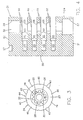
- housing 21 comprises a single piece construction, within which various cavities, bores, and receiving zones are formed.
- housing 21 comprises a top surface 50, a bottom surface 51, a front panel 52, a rear panel 53, and two side panels 54 and 55.
- housing 21 also incorporates a central, elongated bore 56 extending from top surface 50 to bottom surface 51 which comprises three separate diameters, forming three separate and independent coaxial zones 57, 58, and 59.
- Zone 57 comprises the lowermost zone of bore 56 and extends through bottom surface 51 of housing 21, forming an enlarged cavity therein.
- zone 57 comprises the largest diameter of bore 56 and, consequently, has a diameter which is greater than the diameter of adjacent zone 58. In this way, ledge 86 is formed at the juncture between zone 57 and zone 58.
- Zone 58 comprises the intermediate zone of bore 56 and has a diameter slightly greater than the outside diameter of tumbler sleeves 23. In this way, tumbler sleeves 23 are capable of axial movement through zone 58 of central bore 56.
- zone 58 also comprises an elongated slot or channel 60 formed along one wall of zone 58, providing the release position for each radially extending fin 25 of each tumbler sleeve 23.
- shackle 22 when each locking fin of each tumbler sleeve 23 is aligned with release channel 60, shackle 22 is capable of axial movement, thereby enabling shackle 22 to be removed from its locked position or, if desired, inserted into its locked position, or axially advanced into zone 57 of bore 56 of housing 21, to enable the combination to be changed.
- the final zone of bore 56 is upper zone 59 which comprises the second largest diameter of bore 56.
- the diameter of zone 59 is constructed to enable each tumbler sleeve 23 with its radially extending fin 25 to be easily advanced through zone 59. In this way, assembly of combination lock 20 is easily attained.
- upper zone 59 is constructed for receiving and securely retaining sealing cap 37.
- sealing cap 37 comprises a cylindrical shape formed by outer surface 70 and upper flange 71.
- the diameter of zone 59 is substantially equivalent to the diameter of outer surface 70 of cap 37 in order to require cap 37 to be forced into zone 59 and, once inserted therein, securely affixed thereto.
- washer 35, tumbler sleeves 24, spacer 43, and locking ring 36 are mounted to leg 33 of shackle 22. Then, when dials 24 are mounted in place, the fully assembled leg 33 of shackle 22 is inserted into bore 56 of housing 21. The assembly is then completed for forcing sealing cap 37 into zone 59 of bore 56 until the entire outer surface 70 of cap 37 is fully engaged in zone 59 and peripheral flange 71 contacts top surface 50 of housing 21.
- housing 21 incorporates four separate and independent dial receiving zones 61.
- Each dial receiving zone 61 is formed in juxtaposed spaced aligned parallel relationship with each other, while also being cooperatively associated with zone 58 of central bore 56 and elongated release channel 60.
- each dial receiving zone 61 is defined by an upper surface 62 and a lower surface 63 which are parallel to each other.
- each dial receiving zone 61 is cooperatively associated with a cavity 65, within which spring 42 and pin 41 are positioned for interengagement with dial 24.
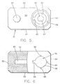
- housing 21 incorporates a plurality of recess slots 66 formed about elongated central bore 56 in an arcuate, juxtaposed, spaced relationship relative to release channel 60.
- three recess slots 66 are formed about zone 58 of central bore 56 at approximately 90° from each other on each wall 62 of each dial receiving zone 61.
- each dial and each tumbler sleeve is directly associated with three separate and independent recess slots 66 in order to assure that false clicking of position locating sounds are produced whenever each dial is rotated.
- the rotation of dial 24 about leg 33 of shackle 22 also causes tumbler sleeve 23 to rotate, since fin 25 is captured in one slot 30 of dial 24. If an unauthorized person attempts to pick combination lock 20, seeking to hear the clicking sound made when each fin 25 enters release channel 60, the individual will be thwarted, since a plurality of false clicks will be produced for each tumbler sleeve 23 and dial 24.
- each tumbler sleeve/dial combination produces four clicks, only one of which represents the actual entry of fin 25 into channel 60.
- the easy and quick picking procedure attainable with most prior art constructions is eliminated, and a virtually pick-free structure is realized.
- the final aperture formed in housing 21 is shackle receiving hole 67 formed in top surface 50 of housing 21 in juxtaposed, spaced, parallel aligned relationship with central bore 56.
- Hole 67 is constructed for receiving terminating end 32 of leg 31 of shackle 22, providing the desired receiving holding zone for terminating end 32 whenever combination lock 22 is in its secured and locked position.
- hole 67 is constructed with a diameter slightly greater than the diameter of leg 31 of shackle 22 in order to assure ease of insertion and withdrawal of leg 31 with hole 67.
- combination lock 20 is depicted in its unlocked position.
- each dial 24 In order to attain the unlocked position, each dial 24 must be rotated to the precise location wherein radially extending fin 25 of each tumbler sleeve 23 is aligned with release channel 60. Once each radially extending fin 25 is positioned within release channel 60, leg 43 of shackle 22 is capable of being axially raised upwardly, removing terminating end 32 of leg 31 from the secure locked interengagement within hole 67.
- each radially extending fin 25 of each tumbler sleeve 23 enters a portion of release channel 60 of housing 21. Since release channel 60 is constructed with dimensions which are slightly greater than radially extending fin 25, fin 25 of each tumbler sleeve 23 is able to easily enter channel 60, but any rotational movement of tumbler sleeve 23 or dial 24 is prevented, since each tumbler sleeve 23 is effectively locked in channel 60.
- leg 31 of shackle 22 is removed from hole 67, shackle 22 is capable of rotational movement about the axis defined by leg 33.
- the longitudinal axial movement of leg 33 of shackle 22 is controlled by the construction of sealing cap 37.
- sealing cap 37 is preferably constructed with a top surface 73 and 75 and 76 defining two separate and distinct substantially circular shaped inside surfaces of cap 37.
- Surface 75 defines a substantially circular shaped portal having a diameter slightly greater than the diameter of shackle 22. In this way, shackle 22 is freely movable in portal 75 both axially and rotationally, while also cooperating with the diameter of shackle 22 to prevent unwanted debris from entering therebetween.
- top surface 73 of sealing cap 37 also incorporates two diametrically opposed radially extending keyway slots 77 and 78 formed therein and cooperating with portal 75.
- Keyway slots 77 and 78 are constructed for cooperating with ribs 38 and 39 of shackle 22, in order to control the axial movement of shackle 22.
- sealing cap 37 incorporates two juxtaposed, spaced, facing, inwardly extending, radial ledges 79 formed on opposed sides of aperture 75 and keyway slots 77 and 78.
- top surface 73 and radially extending ledges 79 cooperate with ribs 38 and 39 of shackle 22 to control the axial movement of shackle 22 relative to housing r 21.
- washer 35 comprises an outer diameter which is less than the diameter of inside surface 76, thereby enabling washer 35 to enter the interior zone defined by inside surface 76.
- outside surface 26 of tumbler sleeve 23 is constructed with a diameter which is greater than the diameter of inside surface 76 of cap 37.
- shackle 22 When shackle 22 is released from engagement with hole 67, shackle 22 is capable of pivoting about the axis defined by leg 33, but is incapable of axially advancing into engagement with bore 56 due to the contact of rib 38 with top surface 73 of cap 37.
- the only positions in which shackle 22 is capable of axial movement is when rib 38 is aligned with keyway slot 77 or keyway slot 78.
- rib 38 is aligned with keyway slot 77, shackle 22 is capable of being moved into its locked position.
- leg 33 of shackle 22 is capable of being axially advanced towards sleeve/bowl 80 until terminating end 34 of leg 33 contacts plate portion 83.
- any further axial movement of leg 33 of shackle 22 is prevented due to the spring biasing force imposed upon sleeve/bowl 80 by spring member 81.
- spring member 81 is mounted under compression between sleeve/bowl 80 and plug 82. Consequently, sleeve/bowl 80 is continuously urged upwardly by spring member 81, holding and maintaining leg 33 of shackle 22 in its normally locked position, as shown in FIGURE 2.
- rim portion 85 of sleeve/bowl 80 is greater than the diameter of zone 58 of bore 56. Consequently, sleeve/bowl 80 is incapable of being forced upwardly by spring member 81 beyond the juncture of zone 57 with zone 58, due to the engagement of rim portion 85 with ledge 86. Since ledge 86 limits the upward travel distance of sleeve/bowl 80, spring member 81 continues to exert its force on sleeve/bowl 80, preventing leg 33 of shackle 22 from moving downwardly, when not desired by the user.
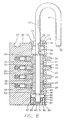
- the user must provide an input force to shackle 22 in order to move leg 33 of shackle 22 downwardly into the position shown in FIGURE 8. This force is required in order to overcome the force of spring member 81 and cause sleeve/bowl 80 to be advanced toward the bottom surface of plug 82. Without providing this downward force, leg 33 of shackle 22 is incapable of moving into the combination resetting position shown in FIGURE 8.
- tumbler sleeves 23 are advanced into housing 21 into a position wherein each radially extending fin 25 of each tumbler sleeve 23 is securely mounted in channel 60 of housing 21.
- radially extending fins 25 of each tumbler sleeve 23 is lowered into a position whereby each radially extending fin 25 is disengaged from slot 30 of each dial 24.
- each dial 24 is free to rotate about the axis defined by shackle 22 since fin 25 has been completely disengaged from each dial 24. In this way, any desired numeral can be aligned with position orientation line 47, thereby enabling the user to select any desired combination of numbers to represent the particular combination for opening lock 20.
- shackle 22 is pivoted to the position wherein rib 38 is aligned with keyway slot 78 and shackle 22 is axially raised upwardly until rib 38 exits slot 78. Once in this raised position, shackle 22 is capable of being freely pivoted about its central axis with leg 31 being engaged with the desired item to be locked and then pivoted into aligned relationship with hole 67 for securing combination lock 20 in the precisely desired location. In addition, sleeve/bowl 80 is free to move upwardly and return to engagement with ledge 86.
- a uniquely constructed combination lock is attained which provides all of the desired functions of a combination lock in a highly effective, easily assembled and easily employed construction capable of being produced r with substantially greater ease and convenience. Furthermore, the construction of the present invention provides assurance that the pre-set combination for the lock will not be accidental changed or altered and incorporates a plurality of means for producing a false click, thereby effectively attaining a combination lock which virtually eliminates unauthorized individuals from gaining access to the combination lock, when in its locked position, using conventional picking techniques.
- the combination lock of the present invention incorporates a virtually sealed construction which eliminates unwanted debris from entering the rotating mechanisms of the combination lock.
- interference of these rotating components with environmental debris is virtually eliminated and a combination lock is attained which is capable of providing long-term use, free from interference or destruction by environmental contamination.
- the present invention can also be implemented using alternate design features.
- One such feature easily employed in the present invention without deviating from the scope of the present invention would be the elimination of rib 39 and the incorporation of a radially extending ledge in leg 33 of shackle 22 to define the stop position for washer 35.
- washer 35 may comprise a ledge or diameter so as to prevent the entry of washer into the cavity formed by inside surface 76 of cap 37. In this way, the axial movement of shackle 22 upwardly would be limited by the contact of washer 35 with the base of cap 37.
Landscapes
- Lock And Its Accessories (AREA)
- Load-Engaging Elements For Cranes (AREA)
Applications Claiming Priority (2)
| Application Number | Priority Date | Filing Date | Title |
|---|---|---|---|
| US391031 | 1999-09-07 | ||
| US10/391,031 US6729166B1 (en) | 2003-03-17 | 2003-03-17 | Combination lock construction |
Publications (2)
| Publication Number | Publication Date |
|---|---|
| EP1460209A2 true EP1460209A2 (de) | 2004-09-22 |
| EP1460209A3 EP1460209A3 (de) | 2005-10-05 |
Family
ID=32176394
Family Applications (1)
| Application Number | Title | Priority Date | Filing Date |
|---|---|---|---|
| EP20030257066 Withdrawn EP1460209A3 (de) | 2003-03-17 | 2003-11-08 | Kombinationsschlösser |
Country Status (2)
| Country | Link |
|---|---|
| US (1) | US6729166B1 (de) |
| EP (1) | EP1460209A3 (de) |
Families Citing this family (38)
| Publication number | Priority date | Publication date | Assignee | Title |
|---|---|---|---|---|
| TW590146U (en) | 2003-05-14 | 2004-06-01 | Sinox Co Ltd | Padlock structure with hook locking and opening |
| US7021092B2 (en) | 2003-05-16 | 2006-04-04 | Stanton Concepts Inc. | Multiple function lock |
| US7434426B2 (en) | 2003-05-16 | 2008-10-14 | Stanton Concepts Inc. | Multiple function lock |
| US7424812B2 (en) | 2003-05-16 | 2008-09-16 | Stanton Concepts Inc. | Multiple function lock |
| US20080060390A1 (en) * | 2003-09-29 | 2008-03-13 | Yu Chun T | Padlock with combination lock |
| US6817215B1 (en) * | 2003-10-10 | 2004-11-16 | Meng-Fu Chen | Steering wheel lock |
| US6904776B1 (en) * | 2004-01-12 | 2005-06-14 | Chu Pao-Feng Lin | Combination lock capable of being opened by a key |
| US6848283B1 (en) * | 2004-04-13 | 2005-02-01 | Chu Pao-Feng Lin | Combination lock capable of being opened by a key or inhibited the same |
| TWI235777B (en) * | 2004-04-23 | 2005-07-11 | Sinox Co Ltd | Lock |
| US7712342B2 (en) | 2004-07-22 | 2010-05-11 | Stanton Concepts Inc. | Tool operated combination lock |
| US7694542B2 (en) | 2004-07-22 | 2010-04-13 | Stanton Concepts Inc. | Tool operated combination lock |
| WO2006016280A2 (en) * | 2004-08-03 | 2006-02-16 | The Sun Lock Company Ltd. | High security padlock construction |
| US8353184B2 (en) | 2005-01-21 | 2013-01-15 | Sinox Company Ltd. | Tamper indicating padlock |
| US7047773B1 (en) * | 2005-06-07 | 2006-05-23 | Fu Chuan Lin | Combination lock and padlock combination |
| US20070136778A1 (en) * | 2005-12-09 | 2007-06-14 | Ari Birger | Controller and control method for media retrieval, routing and playback |
| TWI292006B (en) | 2006-01-05 | 2008-01-01 | Sinox Co Ltd | Lock box |
| US20100313616A1 (en) * | 2009-06-10 | 2010-12-16 | Aba Ufo Internatonal Corp. | Combination lock cylinder |
| KR200464724Y1 (ko) | 2011-01-26 | 2013-01-16 | 이상곤 | 번호교체용 다이얼 자물쇠 |
| USD668929S1 (en) * | 2011-09-27 | 2012-10-16 | Wordlock, Inc. | Combination lock |
| USD678751S1 (en) * | 2011-09-27 | 2013-03-26 | Wordlock, Inc. | Combination lock |
| GB2540522B (en) | 2014-05-07 | 2020-09-09 | Sun Lock Co Ltd | Padlock with fully integrated dual locking mechanism with a lost code defining system |
| US9487969B2 (en) * | 2014-10-10 | 2016-11-08 | The Sun Lock Company Ltd. | Combination padlock with anti-pick and anti-peek mechanism |
| US9803398B2 (en) | 2015-06-30 | 2017-10-31 | The Sun Lock Company Ltd. | Combination padlock with dual locking and advanced anti-pick mechanism |
| US9890559B2 (en) | 2015-03-25 | 2018-02-13 | The Sun Lock Company, Ltd. | Padlock with fully integrated dual locking mechanism with reset mechanism |
| US10221591B2 (en) | 2015-07-07 | 2019-03-05 | The Sun Lock Company, Ltd. | Padlock with fully integrated dual locking mechanism with reset mechanism |
| US10047541B2 (en) | 2015-09-16 | 2018-08-14 | The Sun Lock Company, Ltd. | Dual locking system with user controllable plate |
| US10443272B2 (en) | 2017-05-04 | 2019-10-15 | The Sun Lock Company, Ltd. | Dual unlocking mode padlock |
| US11199025B2 (en) | 2018-12-18 | 2021-12-14 | The Sun Lock Company Limited | Combination padlock with anti-picking and decode mechanism |
| US11346127B2 (en) | 2019-06-27 | 2022-05-31 | The Sun Lock Company Limited | Hook lock with dual locking function |
| US11261622B2 (en) | 2019-08-28 | 2022-03-01 | The Sun Lock Company Limited | High security combination padlock with ease of use reset mechanism |
| USD902691S1 (en) | 2019-10-01 | 2020-11-24 | The Sun Lock Company Limited | Combination padlock |
| USD914481S1 (en) | 2019-10-15 | 2021-03-30 | The Sun Lock Company Limited | Padlock |
| US11713593B2 (en) | 2019-12-18 | 2023-08-01 | The Sun Lock Company Limited | Hook lock with dual locking function with key captive design |
| GB2600208B (en) | 2020-08-28 | 2023-08-23 | Sun Lock Co Ltd | Dual locking combination padlock with decode function |
| US12281500B2 (en) | 2021-08-06 | 2025-04-22 | The Sun Lock Company Limited | High security combination padlock and locking bar with advanced anti-picking mechanism |
| USD1011865S1 (en) | 2022-01-05 | 2024-01-23 | The Sun Lock Company Limited | Combination padlock |
| US12607043B2 (en) | 2023-01-19 | 2026-04-21 | The Sun Lock Company Limited | Anti-picking combination padlock |
| USD1102867S1 (en) | 2023-09-06 | 2025-11-25 | The Sun Lock Company Limited | Combination padlock |
Family Cites Families (18)
| Publication number | Priority date | Publication date | Assignee | Title |
|---|---|---|---|---|
| US589844A (en) * | 1897-09-14 | Permutation-lock | ||
| US1580573A (en) * | 1924-03-08 | 1926-04-13 | Schara Mfg Corp | Permutation-lock construction |
| US1643752A (en) * | 1925-05-19 | 1927-09-27 | Rosenhahn Carl | Lock |
| US3386271A (en) * | 1966-05-20 | 1968-06-04 | Coats & Clark | Combination padlock |
| US3388572A (en) * | 1966-12-13 | 1968-06-18 | Coats & Clark | Combination locks with concealed resettable control |
| US3410121A (en) * | 1966-12-13 | 1968-11-12 | Coats & Clark | Resettable combination padlock |
| US3592027A (en) * | 1968-09-30 | 1971-07-13 | Wako Kinzokie Kk | Combination lock |
| US3720082A (en) * | 1971-09-13 | 1973-03-13 | Kidde Co Presto Lock Div | Combination padlock |
| US4444029A (en) * | 1982-02-16 | 1984-04-24 | Presto Lock, Inc. | Combination lock with anti-pick feature |
| US4733548A (en) * | 1987-02-24 | 1988-03-29 | Ling Chong Kuan | Anti-sensing locking mechanism for combination padlock |
| US4829794A (en) * | 1988-05-09 | 1989-05-16 | National Manufacturing Co. | Padlock |
| US5715709A (en) * | 1996-01-11 | 1998-02-10 | Sunrich Company | Combination lock construction |
| CN2387228Y (zh) * | 1998-07-27 | 2000-07-12 | 黎端宇 | 旋转拨号盘式暗码挂锁的外套结构 |
| US6029481A (en) * | 1998-12-23 | 2000-02-29 | The Sun Lock Company | Combination padlock construction with manual activation |
| US6474116B1 (en) * | 1998-12-23 | 2002-11-05 | The Sun Lock Company Ltd. | Combination lock with dual locking means |
| US6035672A (en) * | 1998-12-23 | 2000-03-14 | The Sun Lock Company Ltd | Combination padlock construction with positive visual indicator |
| US6176109B1 (en) * | 1999-09-28 | 2001-01-23 | Kwong Wah Lock Manufactory Ltd. | Combination lock |
| US6546763B1 (en) * | 2001-11-30 | 2003-04-15 | Jeffrey A. Pielach | Lock assembly |
-
2003
- 2003-03-17 US US10/391,031 patent/US6729166B1/en not_active Expired - Fee Related
- 2003-11-08 EP EP20030257066 patent/EP1460209A3/de not_active Withdrawn
Also Published As
| Publication number | Publication date |
|---|---|
| US6729166B1 (en) | 2004-05-04 |
| EP1460209A3 (de) | 2005-10-05 |
Similar Documents
| Publication | Publication Date | Title |
|---|---|---|
| US6729166B1 (en) | Combination lock construction | |
| US5715709A (en) | Combination lock construction | |
| US6035672A (en) | Combination padlock construction with positive visual indicator | |
| US6029481A (en) | Combination padlock construction with manual activation | |
| US6474116B1 (en) | Combination lock with dual locking means | |
| US7140209B2 (en) | Padlock with fully integrated dual locking systems | |
| US6883355B2 (en) | High security combination padlock with locking bar | |
| US8261583B2 (en) | High security, dual-mode padlock construction | |
| US7117698B2 (en) | High security padlock construction | |
| US4282731A (en) | Pin-tumbler-type lock having antipick security action | |
| US20060243005A1 (en) | Padlock with fully integrated dual locking systems | |
| US10428556B2 (en) | High security locking system which forms a deviating picking path and associated deviated key | |
| US20110083479A1 (en) | Cylinder lockset with a focusing apparatus | |
| US5921118A (en) | Shift lever lock structure of a car | |
| WO2016072832A1 (en) | Lock core complete with locking mechanism sealed therein | |
| US4358942A (en) | Combination lock | |
| GB2082240A (en) | A lock barrel with shutter | |
| JP4064082B2 (ja) | 錠構造 | |
| JP3090438B2 (ja) | 錠キャップ | |
| CA1065638A (en) | High security deadbolt lock | |
| KR200241007Y1 (ko) | 보조키이 커버 | |
| JPH08218692A (ja) | ドア用補助錠 | |
| JP2003138795A (ja) | サムターン | |
| KR20050032879A (ko) | 도난방지용 자유회전 도어록 장치 | |
| KR200329235Y1 (ko) | 도어용 잠금장치 |
Legal Events
| Date | Code | Title | Description |
|---|---|---|---|
| PUAI | Public reference made under article 153(3) epc to a published international application that has entered the european phase |
Free format text: ORIGINAL CODE: 0009012 |
|
| AK | Designated contracting states |
Kind code of ref document: A2 Designated state(s): AT BE BG CH CY CZ DE DK EE ES FI FR GB GR HU IE IT LI LU MC NL PT RO SE SI SK TR |
|
| AX | Request for extension of the european patent |
Extension state: AL LT LV MK |
|
| PUAL | Search report despatched |
Free format text: ORIGINAL CODE: 0009013 |
|
| AK | Designated contracting states |
Kind code of ref document: A3 Designated state(s): AT BE BG CH CY CZ DE DK EE ES FI FR GB GR HU IE IT LI LU MC NL PT RO SE SI SK TR |
|
| AX | Request for extension of the european patent |
Extension state: AL LT LV MK |
|
| AKX | Designation fees paid | ||
| REG | Reference to a national code |
Ref country code: DE Ref legal event code: 8566 |
|
| STAA | Information on the status of an ep patent application or granted ep patent |
Free format text: STATUS: THE APPLICATION IS DEEMED TO BE WITHDRAWN |
|
| 18D | Application deemed to be withdrawn |
Effective date: 20060406 |