EP1460227A2 - Sliding door trolley inserted and blocked in a bore - Google Patents
Sliding door trolley inserted and blocked in a bore Download PDFInfo
- Publication number
- EP1460227A2 EP1460227A2 EP04405021A EP04405021A EP1460227A2 EP 1460227 A2 EP1460227 A2 EP 1460227A2 EP 04405021 A EP04405021 A EP 04405021A EP 04405021 A EP04405021 A EP 04405021A EP 1460227 A2 EP1460227 A2 EP 1460227A2
- Authority
- EP
- European Patent Office
- Prior art keywords
- drive
- eccentric part
- bore
- drive according
- pin
- Prior art date
- Legal status (The legal status is an assumption and is not a legal conclusion. Google has not performed a legal analysis and makes no representation as to the accuracy of the status listed.)
- Withdrawn
Links
- 238000004873 anchoring Methods 0.000 claims description 8
- 238000002347 injection Methods 0.000 claims description 2
- 239000007924 injection Substances 0.000 claims description 2
- 230000037431 insertion Effects 0.000 description 2
- 238000003780 insertion Methods 0.000 description 2
- 239000011093 chipboard Substances 0.000 description 1
- 210000000078 claw Anatomy 0.000 description 1
- 230000001419 dependent effect Effects 0.000 description 1
- 238000009434 installation Methods 0.000 description 1
- 239000000463 material Substances 0.000 description 1
- 210000002435 tendon Anatomy 0.000 description 1
Images
Classifications
-
- E—FIXED CONSTRUCTIONS
- E05—LOCKS; KEYS; WINDOW OR DOOR FITTINGS; SAFES
- E05D—HINGES OR SUSPENSION DEVICES FOR DOORS, WINDOWS OR WINGS
- E05D15/00—Suspension arrangements for wings
- E05D15/06—Suspension arrangements for wings for wings sliding horizontally more or less in their own plane
- E05D15/0621—Details, e.g. suspension or supporting guides
- E05D15/0626—Details, e.g. suspension or supporting guides for wings suspended at the top
- E05D15/063—Details, e.g. suspension or supporting guides for wings suspended at the top on wheels with fixed axis
-
- E—FIXED CONSTRUCTIONS
- E05—LOCKS; KEYS; WINDOW OR DOOR FITTINGS; SAFES
- E05Y—INDEXING SCHEME ASSOCIATED WITH SUBCLASSES E05D AND E05F, RELATING TO CONSTRUCTION ELEMENTS, ELECTRIC CONTROL, POWER SUPPLY, POWER SIGNAL OR TRANSMISSION, USER INTERFACES, MOUNTING OR COUPLING, DETAILS, ACCESSORIES, AUXILIARY OPERATIONS NOT OTHERWISE PROVIDED FOR, APPLICATION THEREOF
- E05Y2201/00—Constructional elements; Accessories therefor
- E05Y2201/60—Suspension or transmission members; Accessories therefor
- E05Y2201/622—Suspension or transmission members elements
- E05Y2201/638—Cams; Ramps
-
- E—FIXED CONSTRUCTIONS
- E05—LOCKS; KEYS; WINDOW OR DOOR FITTINGS; SAFES
- E05Y—INDEXING SCHEME ASSOCIATED WITH SUBCLASSES E05D AND E05F, RELATING TO CONSTRUCTION ELEMENTS, ELECTRIC CONTROL, POWER SUPPLY, POWER SIGNAL OR TRANSMISSION, USER INTERFACES, MOUNTING OR COUPLING, DETAILS, ACCESSORIES, AUXILIARY OPERATIONS NOT OTHERWISE PROVIDED FOR, APPLICATION THEREOF
- E05Y2201/00—Constructional elements; Accessories therefor
- E05Y2201/60—Suspension or transmission members; Accessories therefor
- E05Y2201/622—Suspension or transmission members elements
- E05Y2201/64—Carriers
-
- E—FIXED CONSTRUCTIONS
- E05—LOCKS; KEYS; WINDOW OR DOOR FITTINGS; SAFES
- E05Y—INDEXING SCHEME ASSOCIATED WITH SUBCLASSES E05D AND E05F, RELATING TO CONSTRUCTION ELEMENTS, ELECTRIC CONTROL, POWER SUPPLY, POWER SIGNAL OR TRANSMISSION, USER INTERFACES, MOUNTING OR COUPLING, DETAILS, ACCESSORIES, AUXILIARY OPERATIONS NOT OTHERWISE PROVIDED FOR, APPLICATION THEREOF
- E05Y2600/00—Mounting or coupling arrangements for elements provided for in this subclass
- E05Y2600/10—Adjustable
- E05Y2600/20—Adjustable with specific transmission movement
-
- E—FIXED CONSTRUCTIONS
- E05—LOCKS; KEYS; WINDOW OR DOOR FITTINGS; SAFES
- E05Y—INDEXING SCHEME ASSOCIATED WITH SUBCLASSES E05D AND E05F, RELATING TO CONSTRUCTION ELEMENTS, ELECTRIC CONTROL, POWER SUPPLY, POWER SIGNAL OR TRANSMISSION, USER INTERFACES, MOUNTING OR COUPLING, DETAILS, ACCESSORIES, AUXILIARY OPERATIONS NOT OTHERWISE PROVIDED FOR, APPLICATION THEREOF
- E05Y2600/00—Mounting or coupling arrangements for elements provided for in this subclass
- E05Y2600/40—Mounting location; Visibility of the elements
- E05Y2600/46—Mounting location; Visibility of the elements in or on the wing
-
- E—FIXED CONSTRUCTIONS
- E05—LOCKS; KEYS; WINDOW OR DOOR FITTINGS; SAFES
- E05Y—INDEXING SCHEME ASSOCIATED WITH SUBCLASSES E05D AND E05F, RELATING TO CONSTRUCTION ELEMENTS, ELECTRIC CONTROL, POWER SUPPLY, POWER SIGNAL OR TRANSMISSION, USER INTERFACES, MOUNTING OR COUPLING, DETAILS, ACCESSORIES, AUXILIARY OPERATIONS NOT OTHERWISE PROVIDED FOR, APPLICATION THEREOF
- E05Y2900/00—Application of doors, windows, wings or fittings thereof
- E05Y2900/20—Application of doors, windows, wings or fittings thereof for furniture, e.g. cabinets
Definitions
- the subject matter of the invention is a drive for sliding doors that can be inserted and locked into a pot bore according to the preamble of patent claim 1.
- Sliding doors of cabinets have long been suspended from drives that are slidably mounted in a track on the ceiling of the cabinet.
- Such drives can either be designed as sliders or they have one or more pairs of rollers that roll within the running rail.
- the drive is anchored, particularly in mass production, by inserting the anchoring part into a pot hole.
- the cost pressure on the manufacturers of furniture with sliding doors means that conventional drives that have to be screwed to the sliding door after being inserted into the pot hole are too expensive and also require too much assembly effort.
- a fitting for a sliding door which, instead of a screw connection, has disc-shaped pins, the periphery of which is either ring-like or provided with grooves which are intended to claw in the pot bore after being pressed in or hammered in.
- Such fittings are easy to install, but they do not guarantee a secure hold, since even small plus tolerances in the bore or minus tolerances on the fitting can lead to a reduction in the holding forces of the fitting on the door.
- the cheap chipboard often used for door production offers little stability.
- Another drive is known from the prior art, which is designed like the conventional one, but is no longer screwed to the sliding door for anchoring it within the pot bore, but is held by a tensioning bracket attached to the drive. With this drive, the assembly effort can be reduced, but the positional stability of the disk-shaped drive body in the circular cup bore is not guaranteed.
- the object of the present invention is to provide an inexpensive drive with little Installation effort used in the sliding door and can be anchored tensile and torsion-proof. This object is achieved by a drive according to the features of claim 1. Advantageous embodiments of the invention are defined in the dependent claims.
- the drive body molded from plastic with two cylindrical projections to engage in two adjacent cup bores can be securely anchored in one of the two projections in the pane door with a single eccentric part.
- a twist or imprecise mounting of the drive is excluded from the outset.
- a non-positive and positive anchoring is achieved by rotating the eccentric part within the extension and the resulting feeding of the extension.
- the eccentric part is connected by a connection, i.e. a thin thread of material attached to the drive. This ensures that the eccentric part is available for assembly with the drive. It can also be injection molded in one piece.
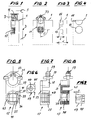
- FIG. 1 the upper edge and part of a sliding door is shown with reference numeral 1, which is installed in a cabinet 3, of which the front edge 5 of the ceiling and sections of a side wall 7 are visible.
- a guide rail 9 with internal guideways is inserted in a groove 11 on the underside of the ceiling 5 of the cabinet 3.
- a drive 17 is held immovably in two pot bores 13 and 15.
- the two Pot holes 13, 15 have a depth t which corresponds to approximately half the thickness s of the sliding door 1.
- the pot hole 13 below is cylindrical; the upper one can also have a circular cross section or, as shown in the figures, only a circular section.
- the drive 17 and the eccentric part 19 used to fasten the latter are shown in FIGS. 5 to 9.
- the drive 17 comprises an anchoring part 21 with an anchoring plate 23, on which a first cylindrical extension in the form of a pin 25 is attached at the bottom and a second cylindrical pin 27 or - as shown in the figures - a pin 27 with a circular cross-section are formed on the top.
- the upper pin 27 carries on its upper side the carriage 29, which in the example shown comprises two sliding shoes 31 which engage in the rail 9.
- a pair of rollers can be used on the drive 17 according to the invention, the shaft of which can be clicked into a recess 33 from below after the axial insertion (pair of rollers and shaft not shown).
- the lower pin 25 has an outer cylindrical jacket 36 which is pierced by axially parallel incisions 35.
- the incisions or openings 35 enable a spreading, ie enlarging the diameter of the lower pin 25 when the eccentric part 19 is inserted into the bore 37 in the lower pin 25 and rotated by 90 degrees.
- the eccentric part 19 has a flange-shaped section 45 with an essentially square cross section, two quarter circles being formed instead of two edges meeting at right angles (see arrow p in FIG. 6).
- the square-rounded cross section extends axially only over an area X and serves to axially position the eccentric part 19 within a correspondingly designed step-shaped recess 39.
- the step-shaped recess 39 comprises two rectilinear tendons 41, which are each connected to one another by an arcuate section 43 and serve as rotary stops for the eccentric part 19 (cf. FIG. 5).
- the section of the eccentric part 19 adjoining the flange-shaped section 45 is cylindrical and has in its outer surface two grooves 47 displaced by 180 °, the depth of which increases over 90 degrees from 0 to a predetermined value, for example 0.5 mm.
- These grooves 47 are intended to receive a rib 49 attached to the pin 25 in the bore 37.
- the rib 49 comes into engagement with the grooves 47 when the eccentric part 19 is inserted into the bore 37.
- the insertion into the bore 37 can already at the manufacturer of the drive or only at the furniture manufacturer.
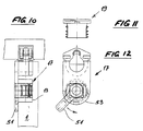
- a flap 51 which can be swiveled by hand takes place.
- the flap 51 preferably projects beyond the drive body 53 in the radial direction.
- the pin 25 is spread apart for the purpose of wedging the drive in the sliding door 1 by a 90 ° rotation of the eccentric part 19, for example by means of a screwdriver, preferably by means of a hexagon screwdriver, which is inserted into a hexagon hole 50 provided for this purpose on the end face of the eccentric part 19. If a tab 51 is attached to the eccentric part 19, the 90 ° rotation can be carried out by hand without tools and without eye contact with the drive.
Landscapes
- Engineering & Computer Science (AREA)
- Mechanical Engineering (AREA)
- Transmission Devices (AREA)
- Support Devices For Sliding Doors (AREA)
- Hinges (AREA)
Abstract
Das in eine Topfbohrung einschieb- und in dieser arretierbare Laufwerk (17) umfasst zwei Zapfen (25,27), welche einzeln in zwei übereinanderliegende Topfbohrungen eingreifen. Ein in den unteren Zapfen (25) einschiebbarer Exzenterteil kann durch dessen Drehung um 90° den Zapfen 25 bzw. dessen Mantel spreizen und so das Laufwerk (17) innerhalb der Topfbohrung fixieren. Das Laufwerk (17) kann mit einer Gleitführung (Führungsschuhe 31) oder mit einer Rollenführung versehen sein. Es lässt sich kostengünstig herstellen und benötigt wenig Montageaufwand.The drive (17) which can be inserted into a pot hole and locked in it comprises two pins (25, 27) which individually engage in two pot holes lying one above the other. An eccentric part which can be pushed into the lower pin (25) can spread the pin 25 or its jacket by rotating it by 90 ° and thus fix the drive (17) within the pot bore. The drive (17) can be provided with a sliding guide (guide shoes 31) or with a roller guide. It can be manufactured inexpensively and requires little assembly effort.
Description
Gegenstand der Erfindung ist ein in eine Topfbohrung einschieb- und arretierbares Laufwerk für Schiebetüren gemäss Oberbegriff des Patentanspruchs 1.The subject matter of the invention is a drive for sliding doors that can be inserted and locked into a pot bore according to the preamble of
Schiebetüren von Schränken werden seit langem an Laufwerken aufgehängt, die in einer Laufschiene an der Decke des Schrankes verschiebbar gelagert sind. Solche Laufwerke können entweder als Gleiter ausgebildet sein oder sie weisen ein oder mehrere Rollenpaare auf, die innerhalb der Laufschiene abwälzen. Die Verankerung des Laufwerks erfolgt insbesondere bei der Massenfertigung durch Einschieben des Verankerungsteils in eine Topfbohrung.
Der Kostendruck auf die Hersteller von Möbeln mit Schiebetüren führt dazu, dass herkömmliche Laufwerke, die nach dem Einsetzen in die Topfbohrung mit der Schiebetür verschraubt werden müssen, zu teuer sind und zudem einen zu grossen Montageaufwand benötigen.Sliding doors of cabinets have long been suspended from drives that are slidably mounted in a track on the ceiling of the cabinet. Such drives can either be designed as sliders or they have one or more pairs of rollers that roll within the running rail. The drive is anchored, particularly in mass production, by inserting the anchoring part into a pot hole.
The cost pressure on the manufacturers of furniture with sliding doors means that conventional drives that have to be screwed to the sliding door after being inserted into the pot hole are too expensive and also require too much assembly effort.
Aus der Schweizer Patentschrift 516724 ist weiter ein Beschlag für eine Schiebetür bekannt, der anstelle einer Verschraubung scheibenförmige Zapfen aufweist, deren Peripherie entweder ringwulstartig ausgebildet oder mit Rillen versehen ist, die sich in der Topfbohrung nach dem Einpressen oder Einschlagen mit einem Hammer festkrallen sollen. Solche Beschläge sind zwar einfach zu montieren, sie garantieren aber keinen sicheren Halt, da bereits geringe Plus-Toleranzen in der Bohrung oder Minus-Toleranzen am Beschlag zu einer Verringerung der Haltekräfte des Beschlags an der Türe führen können. Zudem bieten die für die Türherstellung oft verwendeten billigen Spanplatten wenig Haltefestigkeit.From the Swiss patent 516724 a fitting for a sliding door is also known which, instead of a screw connection, has disc-shaped pins, the periphery of which is either ring-like or provided with grooves which are intended to claw in the pot bore after being pressed in or hammered in. Such fittings are easy to install, but they do not guarantee a secure hold, since even small plus tolerances in the bore or minus tolerances on the fitting can lead to a reduction in the holding forces of the fitting on the door. In addition, the cheap chipboard often used for door production offers little stability.
Aus dem Stand der Technik ist ein weiteres Laufwerk bekannt, das wie die herkömmlichen ausgebildet ist, jedoch für dessen Verankerung innerhalb der Topfbohrung nicht mehr mit der Schiebetür verschraubt wird, sondern durch einen am Laufwerk angebrachten Spannbügel gehalten wird. Mit diesem Laufwerk kann wohl der Montageaufwand verringert werden, die Lagestabilität des scheibenförmigen Laufwerkkörpers in der kreisrunden Topfbohrung ist jedoch nicht sichergesellt.Another drive is known from the prior art, which is designed like the conventional one, but is no longer screwed to the sliding door for anchoring it within the pot bore, but is held by a tensioning bracket attached to the drive. With this drive, the assembly effort can be reduced, but the positional stability of the disk-shaped drive body in the circular cup bore is not guaranteed.
Die Aufgabe der vorliegenden Erfindung besteht darin, ein kostengünstiges Laufwerk zu schaffen, das mit geringem Montageaufwand in die Schiebetür eingesetzt und mit dieser zug- und drehfest verankerbar ist.
Gelöst wird diese Aufgabe durch ein Laufwerk gemäss den Merkmalen des Patentanspruchs 1. Vorteilhafte Ausgestaltungen der Erfindung sind in den abhängigen Ansprüchen definiert.The object of the present invention is to provide an inexpensive drive with little Installation effort used in the sliding door and can be anchored tensile and torsion-proof.
This object is achieved by a drive according to the features of
Der aus Kunststoff gespritzte Laufwerkkörper mit zwei zylindrischen, in zwei benachbarte Topfbohrungen einzugreifen bestimmten Fortsätzen kann mit einem einzigen Exzenterteil in einen der beiden Fortsätze in der Scheibetür sicher verankert werden. Eine Verdrehung oder unpräzise Montage des Laufwerks ist zum vorneherein ausgeschlossen. Eine kraft- und formschlüssige Verankerung wird durch Drehen des Exzenterteils innerhalb des Fortsatzes und dem daraus resultierenden Speisen des Fortsatzes erreicht. In einer besonders vorteilhaften Ausgestaltung der Erfindung ist das Exzenterteil durch eine Anbindung, d.h. einem dünnen Materialfaden mit dem Laufwerk verbunden. Damit wird erreicht, dass das Exzenterteil für die Montage mit dem Laufwerk zusammenhängend vorliegt. Zudem kann es in einem Arbeitsgang einteilig gespritzt werden.The drive body molded from plastic with two cylindrical projections to engage in two adjacent cup bores can be securely anchored in one of the two projections in the pane door with a single eccentric part. A twist or imprecise mounting of the drive is excluded from the outset. A non-positive and positive anchoring is achieved by rotating the eccentric part within the extension and the resulting feeding of the extension. In a particularly advantageous embodiment of the invention, the eccentric part is connected by a connection, i.e. a thin thread of material attached to the drive. This ensures that the eccentric part is available for assembly with the drive. It can also be injection molded in one piece.
Anhand eines illustrierten Ausführungsbeispiels wird die Erfindung näher erläutert. Es zeigen
Figur 1- einen Vertikalschnitt durch ein in einen Schrank eingebautes Laufwerk für eine Schiebetür,
- Figur 2
- eine Ansicht der Schiebetür schrankseitig,
Figur 3- einen Vertikalschnitt durch die Schiebetür in
Figur 1 ohne Laufwerk, - Figur 4
- eine Ansicht der Topfbohrungen in der Schiebetür ohne Laufwerk,
- Figur 5
- eine Ansicht des Laufwerks ohne Exzenter,
- Figur 6
- eine Ansicht des Exzenters,
Figur 7- eine Seitenansicht des Laufwerks,
- Figur 8
- einen Vertikalschnitt durch das Laufwerk,
- Figur 9
- einen Axialschnitt durch den Exzenter,
- Figur 10
- einen Vertikalschnitt durch ein in einen Schrank eingebautes Laufwerk in einer weiteren Ausführungsform,
- Figur 11
- einen Axialschnitt durch den Exzenter des Ausführungsbeispiels gemäss Figuren 10/12 und
- Figur 12
- eine Ansicht des Laufwerks gemäss Figur 10.
- Figure 1
- a vertical section through a drive for a sliding door built into a cabinet,
- Figure 2
- a view of the sliding door on the cabinet side,
- Figure 3
- 2 shows a vertical section through the sliding door in FIG. 1 without a drive,
- Figure 4
- a view of the pot holes in the sliding door without a drive,
- Figure 5
- a view of the drive without eccentric,
- Figure 6
- a view of the eccentric,
- Figure 7
- a side view of the drive,
- Figure 8
- a vertical section through the drive,
- Figure 9
- an axial section through the eccentric,
- Figure 10
- a vertical section through a drive installed in a cabinet in a further embodiment,
- Figure 11
- an axial section through the eccentric of the embodiment shown in Figures 10/12 and
- Figure 12
- a view of the drive according to Figure 10.
In Figur 1 ist mit Bezugszeichen 1 die Oberkante und ein Teil einer Schiebetür dargestellt, die in einem Schrank 3 eingebaut ist, von dem die Vorderkante 5 der Decke und ausschnittweise eine Seitenwand 7 sichtbar sind. Eine Führungsschiene 9 mit innenlaufenden Führungsbahnen ist in einer Nut 11 an der Unterseite der Decke 5 des Schrankes 3 eingesetzt. In zwei Topfbohrungen 13 und 15 wird ein Laufwerk 17 unverrückbar festgehalten. Die beiden Topfbohrungen 13,15 weisen eine Tiefe t auf, die etwa der Hälfte der Dicke s der Schiebetür 1 entspricht. Die unten liegende Topfbohrung 13 ist zylindrisch; die obere kann ebenfalls einen kreisrunden Querschnitt aufweisen oder, wie in den Figuren dargestellt, nur einen kreisabschnittförmigen.In Figure 1, the upper edge and part of a sliding door is shown with
Das Laufwerk 17 und der zur Befestigung des letzteren dienende Exzenterteil 19 sind in den Figuren 5 bis 9 dargestellt. Das Laufwerk 17 umfasst einen Verankerungsteil 21 mit einer Verankerungsplatte 23, an der unten ein erster zylindrischer Fortsatz in Gestalt eines Zapfens 25 und oben ein zweiter zylindrischer Zapfen 27 oder - wie in den Figuren dargestellt - ein Zapfen 27 mit kreisabschnittförmigem Querschnitt angeformt sind. Der obere Zapfen 27 trägt an seiner Oberseite den Laufwerkwagen 29, der im dargestellten Beispiel zwei Gleitschuhe 31 umfasst, die in die Schiene 9 eingreifen. Alternativ zu den Gleitschuhen 31 kann am erfindungsgemässen Laufwerk 17 ein Rollenpaar eingesetzt werden, dessen Welle nach dem axialen Einschieben von unten in eine Ausnehmung 33 eingeklickt werden kann (Rollenpaar und Welle nicht abgebildet).The
Der untere Zapfen 25 weist einen von achsparallelen Einschnitten 35 durchbrochenen, aussen zylindrischen Mantel 36 auf. Die Einschnitte oder Durchbrüche 35 ermöglichen eine Spreizung, d.h. Durchmesservergrösserung des unteren Zapfens 25, wenn das Exzenterteil 19 in die Bohrung 37 im unteren Zapfen 25 eingeschoben und um 90 Winkelgrade verdreht wird.The
Der Exzenterteil 19 weist einen flanschförmigen Abschnitt 45 mit im wesentlichen quadratischen Querschnitt auf, wobei anstelle von zwei rechtwinklig aufeinander treffenden Kanten zwei Viertelskreise ausgebildet sind (vgl. Pfeil p in Figur 6). Der quadratisch-abgerundete Querschnitt erstreckt sich axial nur über einen Bereich X und dient dazu, das Exzenterteil 19 innerhalb einer entsprechend ausgebildeten stufenförmigen Ausnehmung 39 axial zu positionieren. Die stufenförmige Ausnehmung 39 umfasst zwei geradlinig verlaufende Sehnen 41, die je durch einen kreisbogenförmigen Abschnitt 43 miteinander verbunden sind und als Drehanschläge für das Exzenterteil 19 dienen (vgl. Figur 5). Der an den flanschförmigen Abschnitt 45 anschliessende Abschnitt des Exzenterteils 19 ist zylindrisch ausgebildet und weist in seiner Mantelfläche zwei um 180° verschobene Nuten 47 auf, deren Tiefe über 90 Winkelgrade von 0 bis auf einen vorgegebenen Wert, z.B. 0,5mm ansteigt. Diese Nuten 47 sind dazu bestimmt, eine in der Bohrung 37 am Zapfen 25 angebrachte Rippe 49 aufzunehmen. Die Rippe 49 gelangt in Eingriff mit den Nuten 47, wenn das Exzenterteil 19 in die Bohrung 37 eingeschoben wird. Das Einschieben in die Bohrung 37 kann schon beim Hersteller des Laufwerks oder erst beim Möbelbauer erfolgen.The
Im Ausführungsbeispiel der Erfindung gemäss den Figuren 10 bis 12 tritt an Stelle einer Sechskantbohrung im Exzenterteil 19 ein von Hand schwenkbarer Lappen 51. Der Lappen 51 überragt vorzugsweise den Laufwerkkörper 53 in radialer Richtung.In the exemplary embodiment of the invention according to FIGS. 10 to 12, instead of a hexagonal hole in the
Eine Spreizung des Zapfens 25 zwecks Verkeilung des Laufwerks in der Schiebetür 1 erfolgt durch eine 90°-Drehung des Exzenterteils 19, z.B. mittels eines Schraubendrehers, vorzugsweise mittels eines Sechskantschraubendrehers, der in eine dafür vorgesehene Sechskantbohrung 50 an der Stirnseite des Exzenterteils 19 eingeführt wird.
Ist am Exzenterteil 19 ein Lappen 51 angebracht, so kann die 90°-Drehung werkzeugfrei und auch ohne Blickkontakt zum Laufwerk von Hand erfolgen.The
If a
Claims (6)
dadurch gekennzeichnet, dass
am Verankerungsteil (21) ein erster spreizbarer zylindermantelförmiger Zapfen (25) ausgebildet ist, dessen Mantel (36) im wesentlichen axial verlaufende Schlitze (35) aufweist, dass in einer Bohrung (37) im ersten Zapfen (25) ein als Spreizmittel fungierender Exzenterteil (19) eingesetzt ist, an dessen Mantelfläche mindestens eine Nut (47) mit zunehmender Tiefe ausgebildet ist, welche Nut (47) mit einer Rippe (49) in der Wand der Bohrung (37) zusammenwirkt.Drive (17) for sliding doors (1) which can be inserted and locked into a pot bore (13, 15), comprising an anchoring part (21) and a carriage (29) to be engaged in a guide rail (9), which two parts (21, 29 ) are injection molded from plastic and an expansion means (19) which can be inserted into the anchoring part (21),
characterized in that
On the anchoring part (21), a first expandable cylindrical jacket-shaped pin (25) is formed, the jacket (36) of which has essentially axially extending slots (35), that in an opening (37) in the first pin (25) an eccentric part acting as an expansion means ( 19) is used, on the lateral surface of which at least one groove (47) is formed with increasing depth, which groove (47) interacts with a rib (49) in the wall of the bore (37).
Applications Claiming Priority (2)
| Application Number | Priority Date | Filing Date | Title |
|---|---|---|---|
| CH4732003 | 2003-03-21 | ||
| CH4732003 | 2003-03-21 |
Publications (2)
| Publication Number | Publication Date |
|---|---|
| EP1460227A2 true EP1460227A2 (en) | 2004-09-22 |
| EP1460227A3 EP1460227A3 (en) | 2009-12-09 |
Family
ID=32778593
Family Applications (1)
| Application Number | Title | Priority Date | Filing Date |
|---|---|---|---|
| EP04405021A Withdrawn EP1460227A3 (en) | 2003-03-21 | 2004-01-12 | Sliding door trolley inserted and blocked in a bore |
Country Status (1)
| Country | Link |
|---|---|
| EP (1) | EP1460227A3 (en) |
Citations (1)
| Publication number | Priority date | Publication date | Assignee | Title |
|---|---|---|---|---|
| US3808633A (en) | 1971-03-04 | 1974-05-07 | Trola Gmbh | Furniture fitting, specifically for detachable suspension of a sliding door from a guide rail |
Family Cites Families (3)
| Publication number | Priority date | Publication date | Assignee | Title |
|---|---|---|---|---|
| CH503872A (en) * | 1970-02-10 | 1971-02-28 | Ziegler Franz | Easily demountable sliding door hanger |
| CH552741A (en) * | 1971-03-19 | 1974-08-15 | Trola Gmbh & Co | DRIVE ON A PART THAT SUPPORTS ON A GUIDE, SUCH AS SLIDING DOOR OR SLIDING WINDOW. |
| DE4124727C2 (en) * | 1991-07-25 | 1994-01-27 | Salice Arturo Spa | Fastening element with a dowel-like socket |
-
2004
- 2004-01-12 EP EP04405021A patent/EP1460227A3/en not_active Withdrawn
Patent Citations (1)
| Publication number | Priority date | Publication date | Assignee | Title |
|---|---|---|---|---|
| US3808633A (en) | 1971-03-04 | 1974-05-07 | Trola Gmbh | Furniture fitting, specifically for detachable suspension of a sliding door from a guide rail |
Also Published As
| Publication number | Publication date |
|---|---|
| EP1460227A3 (en) | 2009-12-09 |
Similar Documents
| Publication | Publication Date | Title |
|---|---|---|
| AT404858B (en) | DOOR STOP PART FOR HINGE FURNITURE DESIGNED AS A HINGE POT | |
| DE19949926C1 (en) | Pipe system | |
| WO2015144794A2 (en) | Seal device and fastener | |
| EP1168949A1 (en) | Fixing element with variable lifting height | |
| DE19912474A1 (en) | Fastening arrangement for attaching a component to a C-shaped holding rail | |
| EP2644816B1 (en) | Fixing device for fixing a window pane within a vehicle body of a motor vehicle | |
| DE3741684C2 (en) | ||
| EP2277412B1 (en) | Square furniture base | |
| EP1486639B1 (en) | Lowerable door seal | |
| DE19914189B4 (en) | connecting device | |
| DE19652027C2 (en) | Mounting rail for fastening pipes or the like | |
| EP1460227A2 (en) | Sliding door trolley inserted and blocked in a bore | |
| EP1455096A2 (en) | Helical-type jointing between walls and/or shelwes of furnitures | |
| DE8717745U1 (en) | Device for adjustable fastening of a hinge band (door, window) to a steel frame | |
| EP1460225B1 (en) | Trolley for a sliding door | |
| EP3279480B1 (en) | Device for fixing a ventilator | |
| EP1873404B1 (en) | Mounting element for flat components | |
| EP0395929B1 (en) | Supporting bar for a carrying rail of a wall-or ceiling covering | |
| EP0741222B1 (en) | Adjustable door hinge | |
| DE2839735C2 (en) | ||
| EP1081392A2 (en) | Connection fitting for clamping two parts together | |
| DE7709379U1 (en) | FASTENING DEVICE FOR FITTING PARTS | |
| DE202004003193U1 (en) | Security hinge for door or window has a fixed hinge housing holding a hinge pins with outwards sprung ends and with screw fasteners to secure the extended setting of the pins | |
| CH665675A5 (en) | Adjustable overhang door hinge | |
| WO2020058157A1 (en) | Mounting device for a slide rail |
Legal Events
| Date | Code | Title | Description |
|---|---|---|---|
| PUAI | Public reference made under article 153(3) epc to a published international application that has entered the european phase |
Free format text: ORIGINAL CODE: 0009012 |
|
| AK | Designated contracting states |
Kind code of ref document: A2 Designated state(s): AT BE BG CH CY CZ DE DK EE ES FI FR GB GR HU IE IT LI LU MC NL PT RO SE SI SK TR |
|
| AX | Request for extension of the european patent |
Extension state: AL LT LV MK |
|
| PUAL | Search report despatched |
Free format text: ORIGINAL CODE: 0009013 |
|
| AK | Designated contracting states |
Kind code of ref document: A3 Designated state(s): AT BE BG CH CY CZ DE DK EE ES FI FR GB GR HU IE IT LI LU MC NL PT RO SE SI SK TR |
|
| AX | Request for extension of the european patent |
Extension state: AL LT LV MK |
|
| 17P | Request for examination filed |
Effective date: 20100510 |
|
| AKX | Designation fees paid |
Designated state(s): CH DE LI |
|
| 17Q | First examination report despatched |
Effective date: 20101221 |
|
| STAA | Information on the status of an ep patent application or granted ep patent |
Free format text: STATUS: THE APPLICATION IS DEEMED TO BE WITHDRAWN |
|
| 18D | Application deemed to be withdrawn |
Effective date: 20120703 |