EP1460264A1 - Kraftstoffeinspritzeinrichtung für eine Brennkraftmaschine, insbesondere eines Kraftfahrzeugs - Google Patents
Kraftstoffeinspritzeinrichtung für eine Brennkraftmaschine, insbesondere eines Kraftfahrzeugs Download PDFInfo
- Publication number
- EP1460264A1 EP1460264A1 EP04290554A EP04290554A EP1460264A1 EP 1460264 A1 EP1460264 A1 EP 1460264A1 EP 04290554 A EP04290554 A EP 04290554A EP 04290554 A EP04290554 A EP 04290554A EP 1460264 A1 EP1460264 A1 EP 1460264A1
- Authority
- EP
- European Patent Office
- Prior art keywords
- injector
- cannula
- bore
- nozzle
- ramp
- Prior art date
- Legal status (The legal status is an assumption and is not a legal conclusion. Google has not performed a legal analysis and makes no representation as to the accuracy of the status listed.)
- Granted
Links
- 238000002347 injection Methods 0.000 title claims description 26
- 239000007924 injection Substances 0.000 title claims description 26
- 238000002485 combustion reaction Methods 0.000 title claims description 18
- 239000000446 fuel Substances 0.000 title claims description 13
- 230000000903 blocking effect Effects 0.000 claims abstract description 11
- 241001631457 Cannula Species 0.000 claims description 10
- 238000007789 sealing Methods 0.000 claims description 6
- 238000001125 extrusion Methods 0.000 claims description 5
- 239000000463 material Substances 0.000 claims description 4
- 230000000295 complement effect Effects 0.000 claims description 3
- 238000006073 displacement reaction Methods 0.000 description 3
- 235000021183 entrée Nutrition 0.000 description 2
- 238000004519 manufacturing process Methods 0.000 description 2
- 230000001427 coherent effect Effects 0.000 description 1
- 238000000605 extraction Methods 0.000 description 1
- 238000003780 insertion Methods 0.000 description 1
- 230000037431 insertion Effects 0.000 description 1
- 238000009434 installation Methods 0.000 description 1
Images


Classifications
-
- F—MECHANICAL ENGINEERING; LIGHTING; HEATING; WEAPONS; BLASTING
- F02—COMBUSTION ENGINES; HOT-GAS OR COMBUSTION-PRODUCT ENGINE PLANTS
- F02M—SUPPLYING COMBUSTION ENGINES IN GENERAL WITH COMBUSTIBLE MIXTURES OR CONSTITUENTS THEREOF
- F02M61/00—Fuel-injectors not provided for in groups F02M39/00 - F02M57/00 or F02M67/00
- F02M61/16—Details not provided for in, or of interest apart from, the apparatus of groups F02M61/02 - F02M61/14
- F02M61/168—Assembling; Disassembling; Manufacturing; Adjusting
-
- F—MECHANICAL ENGINEERING; LIGHTING; HEATING; WEAPONS; BLASTING
- F02—COMBUSTION ENGINES; HOT-GAS OR COMBUSTION-PRODUCT ENGINE PLANTS
- F02M—SUPPLYING COMBUSTION ENGINES IN GENERAL WITH COMBUSTIBLE MIXTURES OR CONSTITUENTS THEREOF
- F02M51/00—Fuel-injection apparatus characterised by being operated electrically
- F02M51/005—Arrangement of electrical wires and connections, e.g. wire harness, sockets, plugs; Arrangement of electronic control circuits in or on fuel injection apparatus
-
- F—MECHANICAL ENGINEERING; LIGHTING; HEATING; WEAPONS; BLASTING
- F02—COMBUSTION ENGINES; HOT-GAS OR COMBUSTION-PRODUCT ENGINE PLANTS
- F02M—SUPPLYING COMBUSTION ENGINES IN GENERAL WITH COMBUSTIBLE MIXTURES OR CONSTITUENTS THEREOF
- F02M55/00—Fuel-injection apparatus characterised by their fuel conduits or their venting means; Arrangements of conduits between fuel tank and pump F02M37/00
- F02M55/004—Joints; Sealings
- F02M55/005—Joints; Sealings for high pressure conduits, e.g. connected to pump outlet or to injector inlet
-
- F—MECHANICAL ENGINEERING; LIGHTING; HEATING; WEAPONS; BLASTING
- F02—COMBUSTION ENGINES; HOT-GAS OR COMBUSTION-PRODUCT ENGINE PLANTS
- F02M—SUPPLYING COMBUSTION ENGINES IN GENERAL WITH COMBUSTIBLE MIXTURES OR CONSTITUENTS THEREOF
- F02M55/00—Fuel-injection apparatus characterised by their fuel conduits or their venting means; Arrangements of conduits between fuel tank and pump F02M37/00
- F02M55/02—Conduits between injection pumps and injectors, e.g. conduits between pump and common-rail or conduits between common-rail and injectors
- F02M55/025—Common rails
-
- F—MECHANICAL ENGINEERING; LIGHTING; HEATING; WEAPONS; BLASTING
- F02—COMBUSTION ENGINES; HOT-GAS OR COMBUSTION-PRODUCT ENGINE PLANTS
- F02M—SUPPLYING COMBUSTION ENGINES IN GENERAL WITH COMBUSTIBLE MIXTURES OR CONSTITUENTS THEREOF
- F02M61/00—Fuel-injectors not provided for in groups F02M39/00 - F02M57/00 or F02M67/00
- F02M61/14—Arrangements of injectors with respect to engines; Mounting of injectors
-
- F—MECHANICAL ENGINEERING; LIGHTING; HEATING; WEAPONS; BLASTING
- F02—COMBUSTION ENGINES; HOT-GAS OR COMBUSTION-PRODUCT ENGINE PLANTS
- F02M—SUPPLYING COMBUSTION ENGINES IN GENERAL WITH COMBUSTIBLE MIXTURES OR CONSTITUENTS THEREOF
- F02M2200/00—Details of fuel-injection apparatus, not otherwise provided for
- F02M2200/16—Sealing of fuel injection apparatus not otherwise provided for
-
- F—MECHANICAL ENGINEERING; LIGHTING; HEATING; WEAPONS; BLASTING
- F02—COMBUSTION ENGINES; HOT-GAS OR COMBUSTION-PRODUCT ENGINE PLANTS
- F02M—SUPPLYING COMBUSTION ENGINES IN GENERAL WITH COMBUSTIBLE MIXTURES OR CONSTITUENTS THEREOF
- F02M2200/00—Details of fuel-injection apparatus, not otherwise provided for
- F02M2200/80—Fuel injection apparatus manufacture, repair or assembly
- F02M2200/803—Fuel injection apparatus manufacture, repair or assembly using clamp elements and fastening means; e.g. bolts or screws
-
- F—MECHANICAL ENGINEERING; LIGHTING; HEATING; WEAPONS; BLASTING
- F02—COMBUSTION ENGINES; HOT-GAS OR COMBUSTION-PRODUCT ENGINE PLANTS
- F02M—SUPPLYING COMBUSTION ENGINES IN GENERAL WITH COMBUSTIBLE MIXTURES OR CONSTITUENTS THEREOF
- F02M2200/00—Details of fuel-injection apparatus, not otherwise provided for
- F02M2200/85—Mounting of fuel injection apparatus
- F02M2200/856—Mounting of fuel injection apparatus characterised by mounting injector to fuel or common rail, or vice versa
Definitions
- the present invention relates to a fuel injection device for an internal combustion engine, in particular for a motor vehicle.
- Internal combustion engines include fuel injectors which are connected, on the one hand, to a fuel supply manifold and, on the other hand, to electrical connection means with an engine control computer.
- Each injector has a lower injection end, an upper supply end intended to be connected to the fuel supply rail and a connector connected by electrical cables to an electromagnetic coil disposed inside the injector and controlling the movement of the needle of this injector.
- the feed ramp comprises parallel nozzles and extending substantially perpendicular to the longitudinal axis of the ramp, each of these nozzles being intended to fit on the feed end of an injector.
- the injectors are first mounted on the cylinder head of the engine and the supply ramp is then mounted by placing each nozzle directly on an upper end of an injector or by inserting a socket between the nozzle and the upper end of each injector.
- each injector To obtain a good efficiency of the internal combustion engine and to fight effectively against pollution, each injector must have a precise position in the cylinder head. Thus, during assembly or each intervention in after-sales service, the position of each injector must be adjusted with precision, which leads to tedious operations and thereby multiplies the risks of incorrect adjustment.
- the invention aims to avoid these drawbacks by proposing a fuel injection device which is particularly simple to install on internal combustion engines.
- the invention therefore relates to a fuel injection device for an internal combustion engine, in particular in a motor vehicle, of the type comprising a fuel supply ramp comprising a longitudinal body and, for each injector, a nozzle s' extending substantially perpendicular to the axis of the body and an electrical connection with a connector intended to be connected to an engine control computer, characterized in that it comprises, for each injector, a cannula connecting said injector with the corresponding nozzle of the ramp and comprising, at each of its ends, a ball joint and a locking member in the connection position to form a non-removable assembly comprising the ramp, the cannulas and the injectors.
- FIG 1 there is schematically shown in perspective an injection device designated as a whole by the reference 1 and which is intended to supply the injectors 40 of an internal combustion engine with fuel and electrical energy.
- the injection device comprises four injectors 40 each comprising a lower injection end 41 and an upper supply end 42 intended to be connected to a rail 10 for injection of fuel.
- the supply ramp 10 comprises a longitudinal body 11 pierced with an axial duct 12 intended to be connected to a fuel supply pipe, not shown.
- the ramp 10 also includes four nozzles 13 extending parallel to each other and substantially perpendicular to the longitudinal axis of the body 11 of said ramp 10.
- Each nozzle 13 is pierced with a channel 14 which opens at one end 14a in the axial duct 12 and at another end 14b in a bore 15 formed at the free end of the corresponding nozzle 13.
- the bore 15 comprises, from the end 14b of the channel 14 to the free end of the nozzle 13, a hemispherical bottom 15a, a first cylindrical portion 15b, a second cylindrical portion 15c of larger diameter than the first cylindrical portion 15b and an inlet provided with a chamfer 15d.
- the second cylindrical portion 15c is provided with a groove 16.
- This upper end 42 of the injector 40 has a bore 43 comprising a hemispherical bottom 43a, a first cylindrical portion 43b, a second cylindrical portion 43c of larger diameter than the first cylindrical portion 43b and an inlet provided with a chamfer 43d.
- the second cylindrical portion 43c has a groove 44.
- each nozzle 13 of the ramp 10 has a shape identical to the bore 43 of each injector 40.
- the injection device also comprises, for each injector 40, a cannula 20 for connecting the injector 40 with the nozzle 13 of the ramp 10.
- each cannula 20 comprises, at each of its ends, a ball joint and a locking member in the connection position to form a non-removable assembly comprising the ramp 10, the cannulas 20 and the injectors 40, as will be seen. later.
- the cannula 20 is formed by a body 21 of generally cylindrical shape pierced with an axial channel 22 opening at each end of said body 21 and intended to put in communication the channel 14 of the nozzle 13 with the corresponding injector 40.
- the body 21 of the cannula 20 has two ends, respectively 23 and 24 which are similar, which avoids a particular mounting direction of the cannula 20 thus making it possible to mount the end 23, ie in the bore 15 of the nozzle 13 , either in the bore 43 of the injector 40 and the end 24, or in said bore 15 or in said bore 43.
- the end 23 of the body 21 of the cannula 20 comprises a hemispherical end surface 23a and a cylindrical portion of shape complementary to the bores 15 and 43, comprising a first part 23b and a second part 23c of larger diameter than said first part 23b.
- the part 23c is equipped with a blocking member in the bore 15 or in the bore 43 and which is constituted by an elastic ring 26, of the circlip type mounted in a groove 27.
- This elastic ring 26 is, as is will be seen later, movable between a retracted position in the groove 27 during assembly of the cannula 20 and a projecting position in the groove 16 or 44 of the bore 15 or 43.
- the first part 23b of the cylindrical portion of the end 23 is also provided with a sealing element with the bore 15 or the bore 43 and which is constituted by an O-ring 28 and an anti-extrusion washer 29 mounted in a groove 30.
- the end 24 of the body 21 of the cannula 20 has a hemispherical end surface 24a and a cylindrical portion comprising a first part 24b and a second part 24c of larger diameter.
- the second part 24c is provided with a blocking member which is formed by an elastic ring 31 of the circlip type mounted in a groove 32 and movable, as will be seen later, between a retracted position in the groove 32 during insertion from the end 24 of the cannula 20 in the bore 15 or in the bore 43 and a position projecting into the groove 16 or 44 for blocking the cannula 20.
- the part 24b of the end 24 of the cannula 20 is equipped with a sealing element with the bore 15 or the bore 43 and which is constituted by an O-ring 33 and an anti-extrusion washer 34 mounted in a groove 35.
- the assembly of the assembly constituted by the ramp 10, the cannulas 20 and the injectors 40 is carried out as follows.
- the end 23 of the cannula 20 is fitted into the bore 15 of the nozzle 13 which causes, at first, the displacement of the elastic ring 26 in the retracted position by the chamfer 15d formed at the entry of the bore 15, then the displacement of this elastic ring 26 in a projecting position when this elastic ring 26 is opposite the groove 16.
- the cannula 20 is secured to the ramp 10 and is non-removable due to the inaccessibility of the ring 26 from the outside.
- the seal between the end 23 of the cannula 20 and the bore 15 of the nozzle 13 is produced by the O-ring 28.
- the contact of the hemispherical end surface 23a with the hemispherical bottom 15a forms a ball joint which allows an angular movement of the cannula 20 relative to the nozzle 13.
- each injector 40 is mounted on a cannula 20.
- the end 24 of the body 21 of the cannula 20 is fitted into the bore 43 which causes, during sliding, the displacement of the elastic ring 31 by the chamfer 43d from the end of the bore 43 between a retracted position in the groove 32 and a projecting position when this washer 31 is located opposite the groove 44 to secure the injector 40 with the cannula 20.
- This injector 40 cannot be removed from the cannula 20 of the made of the inaccessibility of the elastic ring 31 from the outside.
- the seal between the end 24 of the cannula 20 and the bore 43 of the injector 40 is obtained by the O-ring 33.
- the contact of the hemispherical end surface 24a with the hemispherical bottom 43a forms a ball which allows angular movement of the cannula 20 relative to the nozzle 13.
- the assembly formed by the ramp 10 comprising the body 11 and the nozzles 13, the cannulas 20 and the injectors 40 form a coherent and non-removable assembly.
- the ramp 10, the cannulas 20 and the upper ends 42 of the injectors 40 are overmolded in a plastic material 45, as shown in FIGS. 1 and 5.
- the plastic material 45 has been removed for one of the cannulas 20.
- the injection device comprises, for each injector, an electrical connection 46 embedded in the plastic 45, connected to an electrical connector, not shown, mounted on the ramp 15 and which is itself intended to be connected to a internal combustion engine control computer.
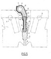
- the assembly thus formed is mounted in a cylinder head A of an internal combustion engine, as shown in Figure 5.
- This injection device allows the mounting of the injectors 40 between the two camshafts B of an internal combustion engine where the passage of the hands for the installation or the extraction of these injectors is particularly difficult .
- each injector 40 is positioned vertically in the cylinder head A and it rests on horizontal surfaces so that the positioning accuracy of each of said injectors 40 is easier to maintain in mass production.
- the injection device according to the invention forms a monobloc assembly, which makes it possible to obtain a correctly adjusted and assembled assembly for good efficiency of the internal combustion engine. Reliability is increased by the fact that it is no longer necessary to dismantle the injectors in after-sales service and these can be paired as original equipment during the manufacture of the internal combustion engine.
- the injection device according to the invention has the advantage of having only one electrical connection for all of the injectors, which allows time to be saved in series connection and better quality. .
Landscapes
- Engineering & Computer Science (AREA)
- Chemical & Material Sciences (AREA)
- Combustion & Propulsion (AREA)
- Mechanical Engineering (AREA)
- General Engineering & Computer Science (AREA)
- Manufacturing & Machinery (AREA)
- Fuel-Injection Apparatus (AREA)
Applications Claiming Priority (2)
| Application Number | Priority Date | Filing Date | Title |
|---|---|---|---|
| FR0303373A FR2852636B1 (fr) | 2003-03-19 | 2003-03-19 | Dispositif d'injection de carburant pour moteur a combustion interne, notamment d'un vehicule automobile. |
| FR0303373 | 2003-03-19 |
Publications (2)
| Publication Number | Publication Date |
|---|---|
| EP1460264A1 true EP1460264A1 (de) | 2004-09-22 |
| EP1460264B1 EP1460264B1 (de) | 2006-05-24 |
Family
ID=32799695
Family Applications (1)
| Application Number | Title | Priority Date | Filing Date |
|---|---|---|---|
| EP04290554A Expired - Lifetime EP1460264B1 (de) | 2003-03-19 | 2004-03-01 | Kraftstoffeinspritzeinrichtung für eine Brennkraftmaschine, insbesondere eines Kraftfahrzeugs |
Country Status (4)
| Country | Link |
|---|---|
| EP (1) | EP1460264B1 (de) |
| AT (1) | ATE327425T1 (de) |
| DE (1) | DE602004000933T2 (de) |
| FR (1) | FR2852636B1 (de) |
Cited By (11)
| Publication number | Priority date | Publication date | Assignee | Title |
|---|---|---|---|---|
| EP1780403A2 (de) | 2005-10-25 | 2007-05-02 | Robert Bosch Gmbh | Brennstoffeinspritzventil |
| WO2008088993A1 (en) * | 2007-01-11 | 2008-07-24 | Millennium Industries, Inc. | Welded fuel injector attachment |
| WO2009058283A1 (en) * | 2007-10-29 | 2009-05-07 | Caterpillar Inc. | Fuel system having a one-piece hollow tube connection |
| EP2093412A1 (de) | 2008-02-19 | 2009-08-26 | Continental Automotive GmbH | Kupplungsvorrichtung |
| CN102032083A (zh) * | 2009-09-29 | 2011-04-27 | 通用汽车环球科技运作公司 | 包括安装有凸轮罩的燃料轨的发动机组件 |
| US7934488B2 (en) | 2008-02-19 | 2011-05-03 | Continental Automotive Gmbh | Coupling device |
| US7976073B2 (en) | 2008-02-19 | 2011-07-12 | Continental Automotive Gmbh | Coupling device |
| US8245697B2 (en) | 2009-01-19 | 2012-08-21 | Continental Automotive Gmbh | Coupling device |
| CN103016228A (zh) * | 2011-09-26 | 2013-04-03 | 株式会社电装 | 燃油轨及使用该燃油轨的燃油喷射装置 |
| EP2910768A1 (de) * | 2014-02-25 | 2015-08-26 | Continental Automotive GmbH | Kraftstoffleistenvorrichtung für einen Verbrennungsmotor und Verfahren zu ihrer Herstellung |
| JP2021148047A (ja) * | 2020-03-18 | 2021-09-27 | 臼井国際産業株式会社 | ガソリン直噴レール |
Families Citing this family (3)
| Publication number | Priority date | Publication date | Assignee | Title |
|---|---|---|---|---|
| EP2090772B1 (de) | 2008-02-15 | 2012-04-25 | Continental Automotive GmbH | Verbindungsanordnung |
| DE102009050337A1 (de) * | 2009-10-22 | 2011-04-28 | GM Global Technology Operations, Inc., Detroit | Bauteileeinheit für ein Kraftstoffsystem einer Brennkraftmaschine sowie Brennkraftmaschine |
| DE102017216643A1 (de) * | 2017-09-20 | 2019-03-21 | Robert Bosch Gmbh | Wassereinspritzvorrichtung einer Brennkraftmaschine |
Citations (4)
| Publication number | Priority date | Publication date | Assignee | Title |
|---|---|---|---|---|
| US6418911B1 (en) * | 2001-07-13 | 2002-07-16 | Siemens Diesel Systems Technology | Device and procedure for coupling a fluid rail with fuel injectors |
| DE10108203A1 (de) * | 2001-02-21 | 2002-08-29 | Bosch Gmbh Robert | Montagebügel und Verfahren zur Montage eines Brennstoffeinspritzventils |
| WO2003006813A2 (en) * | 2001-07-13 | 2003-01-23 | Siemens Diesel Systems Technology Vdo | Device and method for coupling a fluid rail with fuel injectors |
| US6564775B1 (en) * | 1999-08-03 | 2003-05-20 | Aisan Kogyo Kabushiki Kaisha | Fuel delivery pipes |
-
2003
- 2003-03-19 FR FR0303373A patent/FR2852636B1/fr not_active Expired - Fee Related
-
2004
- 2004-03-01 DE DE602004000933T patent/DE602004000933T2/de not_active Expired - Lifetime
- 2004-03-01 AT AT04290554T patent/ATE327425T1/de not_active IP Right Cessation
- 2004-03-01 EP EP04290554A patent/EP1460264B1/de not_active Expired - Lifetime
Patent Citations (4)
| Publication number | Priority date | Publication date | Assignee | Title |
|---|---|---|---|---|
| US6564775B1 (en) * | 1999-08-03 | 2003-05-20 | Aisan Kogyo Kabushiki Kaisha | Fuel delivery pipes |
| DE10108203A1 (de) * | 2001-02-21 | 2002-08-29 | Bosch Gmbh Robert | Montagebügel und Verfahren zur Montage eines Brennstoffeinspritzventils |
| US6418911B1 (en) * | 2001-07-13 | 2002-07-16 | Siemens Diesel Systems Technology | Device and procedure for coupling a fluid rail with fuel injectors |
| WO2003006813A2 (en) * | 2001-07-13 | 2003-01-23 | Siemens Diesel Systems Technology Vdo | Device and method for coupling a fluid rail with fuel injectors |
Cited By (19)
| Publication number | Priority date | Publication date | Assignee | Title |
|---|---|---|---|---|
| EP1780403A3 (de) * | 2005-10-25 | 2007-11-21 | Robert Bosch Gmbh | Brennstoffeinspritzventil |
| DE102005051005B4 (de) * | 2005-10-25 | 2025-01-02 | Robert Bosch Gmbh | Brennstoffeinspritzventil |
| EP1780403A2 (de) | 2005-10-25 | 2007-05-02 | Robert Bosch Gmbh | Brennstoffeinspritzventil |
| WO2008088993A1 (en) * | 2007-01-11 | 2008-07-24 | Millennium Industries, Inc. | Welded fuel injector attachment |
| WO2009058283A1 (en) * | 2007-10-29 | 2009-05-07 | Caterpillar Inc. | Fuel system having a one-piece hollow tube connection |
| US8286612B2 (en) | 2008-02-19 | 2012-10-16 | Continental Automotive Gmbh | Coupling device |
| EP2093412A1 (de) | 2008-02-19 | 2009-08-26 | Continental Automotive GmbH | Kupplungsvorrichtung |
| US7934488B2 (en) | 2008-02-19 | 2011-05-03 | Continental Automotive Gmbh | Coupling device |
| US7976073B2 (en) | 2008-02-19 | 2011-07-12 | Continental Automotive Gmbh | Coupling device |
| US8245697B2 (en) | 2009-01-19 | 2012-08-21 | Continental Automotive Gmbh | Coupling device |
| US8307809B2 (en) | 2009-09-29 | 2012-11-13 | GM Global Technology Operations LLC | Engine assembly including cam cover mounted fuel rail |
| CN102032083A (zh) * | 2009-09-29 | 2011-04-27 | 通用汽车环球科技运作公司 | 包括安装有凸轮罩的燃料轨的发动机组件 |
| CN103016228A (zh) * | 2011-09-26 | 2013-04-03 | 株式会社电装 | 燃油轨及使用该燃油轨的燃油喷射装置 |
| US9062640B2 (en) | 2011-09-26 | 2015-06-23 | Denso Corporation | Fuel rail and fuel injection apparatus using the same |
| CN103016228B (zh) * | 2011-09-26 | 2015-11-18 | 株式会社电装 | 燃油轨及使用该燃油轨的燃油喷射装置 |
| CN105257446A (zh) * | 2011-09-26 | 2016-01-20 | 株式会社电装 | 燃油轨及使用该燃油轨的燃油喷射装置 |
| EP2910768A1 (de) * | 2014-02-25 | 2015-08-26 | Continental Automotive GmbH | Kraftstoffleistenvorrichtung für einen Verbrennungsmotor und Verfahren zu ihrer Herstellung |
| JP2021148047A (ja) * | 2020-03-18 | 2021-09-27 | 臼井国際産業株式会社 | ガソリン直噴レール |
| EP4102049A4 (de) * | 2020-03-18 | 2024-02-28 | Usui Co., Ltd. | Benzindirekteinspritzungsverteilerrohr |
Also Published As
| Publication number | Publication date |
|---|---|
| FR2852636A1 (fr) | 2004-09-24 |
| ATE327425T1 (de) | 2006-06-15 |
| DE602004000933D1 (de) | 2006-06-29 |
| DE602004000933T2 (de) | 2006-12-28 |
| FR2852636B1 (fr) | 2005-06-17 |
| EP1460264B1 (de) | 2006-05-24 |
Similar Documents
| Publication | Publication Date | Title |
|---|---|---|
| EP1460264B1 (de) | Kraftstoffeinspritzeinrichtung für eine Brennkraftmaschine, insbesondere eines Kraftfahrzeugs | |
| EP2545616B1 (de) | Dichten elektrischen verbindung vorrichtung durch eine wand und entsprechendes herstellungsverfahren dafür | |
| EP2071241B1 (de) | Vorrichtung zum Lenken eines Elements in die Öffnung einer Brennkammerwand eines Turbinentriebwerks | |
| US5511527A (en) | Fuel rail assembly with crossover hose | |
| FR2697293A1 (fr) | Dispositif d'alimentation à tubulure intégrée. | |
| EP2088303B1 (de) | Herstellungsverfahren einer Trägerplatte für Drosselkörper und Trägerplatte | |
| EP0357498B1 (de) | Kraftstoffeinspritzvorrichtung mit einer Belüftungskammer | |
| FR2797931A1 (fr) | Dispositif de regulation de l'ecoulement dans une portion de conduit ou un passage et collecteur comprenant un tel dispositif | |
| WO2010061072A1 (fr) | Raccord en deux parties reliees par clip | |
| JP3846337B2 (ja) | インジェクタ固定方法およびインジェクタ固定装置 | |
| FR2868133A1 (fr) | Element de support pour injecteur et conduite d'alimentation en carburant d'un moteur a combustion interne | |
| EP1941201B1 (de) | Verbindungsvorrichtung mit geschweisstem körper | |
| EP2901069A1 (de) | Hydraulischer und elektrischer schnittstellenring für einen turbinenmotor | |
| FR2991727A1 (fr) | Soupape de regulation de pression d'accumulateur haute pression de carburant | |
| EP3601860B1 (de) | Stopfbuchse für eine abgedichtete durchführung einer öffnung einer trennwand | |
| WO2012168131A1 (fr) | Assemblage support charbon | |
| WO2023233101A1 (fr) | Dispositif de raccordement de conduites tubulaires a un circuit de fluide | |
| EP0385820A1 (de) | Anordnung zur Halterung und Positionierung von Kraftstoffinjektoren an einem Verbrennungsmotor | |
| FR3137419A1 (fr) | Pompe à carburant pour l’injection directe de carburant pour les moteurs à combustion interne et valve pour une telle pompe. | |
| EP3814616A1 (de) | Leitvorrichtung in einer brennkammer | |
| EP0539279A1 (de) | Verbinderkappe für elektrische Kabelverbindung | |
| FR2798426A1 (fr) | Dispositif d'admission variable pour moteur thermique et boisseau pour un tel dispositif | |
| FR2887927A1 (fr) | Couvercle de culasse de moteur a combustion | |
| EP2375048B1 (de) | Ansaugluftverteilervorrichtung mit Platten und Verfahren zu ihrer Montage auf einer Brennkraftmaschine | |
| FR2767873A1 (fr) | Dispositif de connexion des injecteurs d'un moteur a combustion interne |
Legal Events
| Date | Code | Title | Description |
|---|---|---|---|
| PUAI | Public reference made under article 153(3) epc to a published international application that has entered the european phase |
Free format text: ORIGINAL CODE: 0009012 |
|
| AK | Designated contracting states |
Kind code of ref document: A1 Designated state(s): AT BE BG CH CY CZ DE DK EE ES FI FR GB GR HU IE IT LI LU MC NL PL PT RO SE SI SK TR |
|
| AX | Request for extension of the european patent |
Extension state: AL HR LT LV MK |
|
| 17P | Request for examination filed |
Effective date: 20050226 |
|
| AKX | Designation fees paid |
Designated state(s): AT BE BG CH CY CZ DE DK EE ES FI FR GB GR HU IE IT LI LU MC NL PL PT RO SE SI SK TR |
|
| GRAP | Despatch of communication of intention to grant a patent |
Free format text: ORIGINAL CODE: EPIDOSNIGR1 |
|
| GRAS | Grant fee paid |
Free format text: ORIGINAL CODE: EPIDOSNIGR3 |
|
| GRAA | (expected) grant |
Free format text: ORIGINAL CODE: 0009210 |
|
| AK | Designated contracting states |
Kind code of ref document: B1 Designated state(s): AT BE BG CH CY CZ DE DK EE ES FI FR GB GR HU IE IT LI LU MC NL PL PT RO SE SI SK TR |
|
| PG25 | Lapsed in a contracting state [announced via postgrant information from national office to epo] |
Ref country code: IT Free format text: LAPSE BECAUSE OF FAILURE TO SUBMIT A TRANSLATION OF THE DESCRIPTION OR TO PAY THE FEE WITHIN THE PRESCRIBED TIME-LIMIT;WARNING: LAPSES OF ITALIAN PATENTS WITH EFFECTIVE DATE BEFORE 2007 MAY HAVE OCCURRED AT ANY TIME BEFORE 2007. THE CORRECT EFFECTIVE DATE MAY BE DIFFERENT FROM THE ONE RECORDED. Effective date: 20060524 Ref country code: NL Free format text: LAPSE BECAUSE OF FAILURE TO SUBMIT A TRANSLATION OF THE DESCRIPTION OR TO PAY THE FEE WITHIN THE PRESCRIBED TIME-LIMIT Effective date: 20060524 Ref country code: SI Free format text: LAPSE BECAUSE OF FAILURE TO SUBMIT A TRANSLATION OF THE DESCRIPTION OR TO PAY THE FEE WITHIN THE PRESCRIBED TIME-LIMIT Effective date: 20060524 Ref country code: CZ Free format text: LAPSE BECAUSE OF FAILURE TO SUBMIT A TRANSLATION OF THE DESCRIPTION OR TO PAY THE FEE WITHIN THE PRESCRIBED TIME-LIMIT Effective date: 20060524 Ref country code: GB Free format text: LAPSE BECAUSE OF FAILURE TO SUBMIT A TRANSLATION OF THE DESCRIPTION OR TO PAY THE FEE WITHIN THE PRESCRIBED TIME-LIMIT Effective date: 20060524 Ref country code: PL Free format text: LAPSE BECAUSE OF FAILURE TO SUBMIT A TRANSLATION OF THE DESCRIPTION OR TO PAY THE FEE WITHIN THE PRESCRIBED TIME-LIMIT Effective date: 20060524 Ref country code: SK Free format text: LAPSE BECAUSE OF FAILURE TO SUBMIT A TRANSLATION OF THE DESCRIPTION OR TO PAY THE FEE WITHIN THE PRESCRIBED TIME-LIMIT Effective date: 20060524 Ref country code: RO Free format text: LAPSE BECAUSE OF FAILURE TO SUBMIT A TRANSLATION OF THE DESCRIPTION OR TO PAY THE FEE WITHIN THE PRESCRIBED TIME-LIMIT Effective date: 20060524 Ref country code: AT Free format text: LAPSE BECAUSE OF FAILURE TO SUBMIT A TRANSLATION OF THE DESCRIPTION OR TO PAY THE FEE WITHIN THE PRESCRIBED TIME-LIMIT Effective date: 20060524 Ref country code: IE Free format text: LAPSE BECAUSE OF FAILURE TO SUBMIT A TRANSLATION OF THE DESCRIPTION OR TO PAY THE FEE WITHIN THE PRESCRIBED TIME-LIMIT Effective date: 20060524 Ref country code: FI Free format text: LAPSE BECAUSE OF FAILURE TO SUBMIT A TRANSLATION OF THE DESCRIPTION OR TO PAY THE FEE WITHIN THE PRESCRIBED TIME-LIMIT Effective date: 20060524 |
|
| REG | Reference to a national code |
Ref country code: GB Ref legal event code: FG4D Free format text: NOT ENGLISH |
|
| REG | Reference to a national code |
Ref country code: CH Ref legal event code: EP |
|
| REG | Reference to a national code |
Ref country code: IE Ref legal event code: FG4D Free format text: LANGUAGE OF EP DOCUMENT: FRENCH |
|
| REF | Corresponds to: |
Ref document number: 602004000933 Country of ref document: DE Date of ref document: 20060629 Kind code of ref document: P |
|
| PG25 | Lapsed in a contracting state [announced via postgrant information from national office to epo] |
Ref country code: SE Free format text: LAPSE BECAUSE OF FAILURE TO SUBMIT A TRANSLATION OF THE DESCRIPTION OR TO PAY THE FEE WITHIN THE PRESCRIBED TIME-LIMIT Effective date: 20060824 Ref country code: DK Free format text: LAPSE BECAUSE OF FAILURE TO SUBMIT A TRANSLATION OF THE DESCRIPTION OR TO PAY THE FEE WITHIN THE PRESCRIBED TIME-LIMIT Effective date: 20060824 |
|
| PG25 | Lapsed in a contracting state [announced via postgrant information from national office to epo] |
Ref country code: ES Free format text: LAPSE BECAUSE OF FAILURE TO SUBMIT A TRANSLATION OF THE DESCRIPTION OR TO PAY THE FEE WITHIN THE PRESCRIBED TIME-LIMIT Effective date: 20060904 |
|
| PG25 | Lapsed in a contracting state [announced via postgrant information from national office to epo] |
Ref country code: PT Free format text: LAPSE BECAUSE OF FAILURE TO SUBMIT A TRANSLATION OF THE DESCRIPTION OR TO PAY THE FEE WITHIN THE PRESCRIBED TIME-LIMIT Effective date: 20061024 |
|
| NLV1 | Nl: lapsed or annulled due to failure to fulfill the requirements of art. 29p and 29m of the patents act | ||
| GBV | Gb: ep patent (uk) treated as always having been void in accordance with gb section 77(7)/1977 [no translation filed] |
Effective date: 20060524 |
|
| REG | Reference to a national code |
Ref country code: IE Ref legal event code: FD4D |
|
| PLBE | No opposition filed within time limit |
Free format text: ORIGINAL CODE: 0009261 |
|
| STAA | Information on the status of an ep patent application or granted ep patent |
Free format text: STATUS: NO OPPOSITION FILED WITHIN TIME LIMIT |
|
| 26N | No opposition filed |
Effective date: 20070227 |
|
| BERE | Be: lapsed |
Owner name: PEUGEOT CITROEN AUTOMOBILES S.A. Effective date: 20070331 |
|
| PG25 | Lapsed in a contracting state [announced via postgrant information from national office to epo] |
Ref country code: BE Free format text: LAPSE BECAUSE OF NON-PAYMENT OF DUE FEES Effective date: 20070331 |
|
| PG25 | Lapsed in a contracting state [announced via postgrant information from national office to epo] |
Ref country code: MC Free format text: LAPSE BECAUSE OF NON-PAYMENT OF DUE FEES Effective date: 20070331 |
|
| PG25 | Lapsed in a contracting state [announced via postgrant information from national office to epo] |
Ref country code: GR Free format text: LAPSE BECAUSE OF FAILURE TO SUBMIT A TRANSLATION OF THE DESCRIPTION OR TO PAY THE FEE WITHIN THE PRESCRIBED TIME-LIMIT Effective date: 20060825 |
|
| PG25 | Lapsed in a contracting state [announced via postgrant information from national office to epo] |
Ref country code: BG Free format text: LAPSE BECAUSE OF FAILURE TO SUBMIT A TRANSLATION OF THE DESCRIPTION OR TO PAY THE FEE WITHIN THE PRESCRIBED TIME-LIMIT Effective date: 20060824 |
|
| PG25 | Lapsed in a contracting state [announced via postgrant information from national office to epo] |
Ref country code: EE Free format text: LAPSE BECAUSE OF FAILURE TO SUBMIT A TRANSLATION OF THE DESCRIPTION OR TO PAY THE FEE WITHIN THE PRESCRIBED TIME-LIMIT Effective date: 20060524 |
|
| REG | Reference to a national code |
Ref country code: CH Ref legal event code: PL |
|
| PG25 | Lapsed in a contracting state [announced via postgrant information from national office to epo] |
Ref country code: CH Free format text: LAPSE BECAUSE OF NON-PAYMENT OF DUE FEES Effective date: 20080331 Ref country code: LI Free format text: LAPSE BECAUSE OF NON-PAYMENT OF DUE FEES Effective date: 20080331 |
|
| PG25 | Lapsed in a contracting state [announced via postgrant information from national office to epo] |
Ref country code: CY Free format text: LAPSE BECAUSE OF FAILURE TO SUBMIT A TRANSLATION OF THE DESCRIPTION OR TO PAY THE FEE WITHIN THE PRESCRIBED TIME-LIMIT Effective date: 20060524 Ref country code: LU Free format text: LAPSE BECAUSE OF NON-PAYMENT OF DUE FEES Effective date: 20070301 |
|
| PG25 | Lapsed in a contracting state [announced via postgrant information from national office to epo] |
Ref country code: TR Free format text: LAPSE BECAUSE OF FAILURE TO SUBMIT A TRANSLATION OF THE DESCRIPTION OR TO PAY THE FEE WITHIN THE PRESCRIBED TIME-LIMIT Effective date: 20060524 Ref country code: HU Free format text: LAPSE BECAUSE OF FAILURE TO SUBMIT A TRANSLATION OF THE DESCRIPTION OR TO PAY THE FEE WITHIN THE PRESCRIBED TIME-LIMIT Effective date: 20061125 |
|
| PGFP | Annual fee paid to national office [announced via postgrant information from national office to epo] |
Ref country code: DE Payment date: 20140220 Year of fee payment: 11 |
|
| PGFP | Annual fee paid to national office [announced via postgrant information from national office to epo] |
Ref country code: FR Payment date: 20140328 Year of fee payment: 11 |
|
| REG | Reference to a national code |
Ref country code: DE Ref legal event code: R119 Ref document number: 602004000933 Country of ref document: DE |
|
| REG | Reference to a national code |
Ref country code: FR Ref legal event code: ST Effective date: 20151130 |
|
| PG25 | Lapsed in a contracting state [announced via postgrant information from national office to epo] |
Ref country code: DE Free format text: LAPSE BECAUSE OF NON-PAYMENT OF DUE FEES Effective date: 20151001 |
|
| PG25 | Lapsed in a contracting state [announced via postgrant information from national office to epo] |
Ref country code: FR Free format text: LAPSE BECAUSE OF NON-PAYMENT OF DUE FEES Effective date: 20150331 |