EP1460300B1 - Procédé de mise en service des freins de stationnement pour freins à disque d'actionnement éléctromécanique. - Google Patents
Procédé de mise en service des freins de stationnement pour freins à disque d'actionnement éléctromécanique. Download PDFInfo
- Publication number
- EP1460300B1 EP1460300B1 EP20040101130 EP04101130A EP1460300B1 EP 1460300 B1 EP1460300 B1 EP 1460300B1 EP 20040101130 EP20040101130 EP 20040101130 EP 04101130 A EP04101130 A EP 04101130A EP 1460300 B1 EP1460300 B1 EP 1460300B1
- Authority
- EP
- European Patent Office
- Prior art keywords
- locking
- mechanical
- determined
- angular
- rotational element
- Prior art date
- Legal status (The legal status is an assumption and is not a legal conclusion. Google has not performed a legal analysis and makes no representation as to the accuracy of the status listed.)
- Expired - Lifetime
Links
- 238000000034 method Methods 0.000 title claims description 9
- 238000001514 detection method Methods 0.000 claims description 5
- 230000005540 biological transmission Effects 0.000 description 4
- 230000004913 activation Effects 0.000 description 3
- 230000000903 blocking effect Effects 0.000 description 1
- 238000001816 cooling Methods 0.000 description 1
Images

Classifications
-
- F—MECHANICAL ENGINEERING; LIGHTING; HEATING; WEAPONS; BLASTING
- F16—ENGINEERING ELEMENTS AND UNITS; GENERAL MEASURES FOR PRODUCING AND MAINTAINING EFFECTIVE FUNCTIONING OF MACHINES OR INSTALLATIONS; THERMAL INSULATION IN GENERAL
- F16D—COUPLINGS FOR TRANSMITTING ROTATION; CLUTCHES; BRAKES
- F16D65/00—Parts or details
- F16D65/14—Actuating mechanisms for brakes; Means for initiating operation at a predetermined position
- F16D65/16—Actuating mechanisms for brakes; Means for initiating operation at a predetermined position arranged in or on the brake
- F16D65/18—Actuating mechanisms for brakes; Means for initiating operation at a predetermined position arranged in or on the brake adapted for drawing members together, e.g. for disc brakes
-
- F—MECHANICAL ENGINEERING; LIGHTING; HEATING; WEAPONS; BLASTING
- F16—ENGINEERING ELEMENTS AND UNITS; GENERAL MEASURES FOR PRODUCING AND MAINTAINING EFFECTIVE FUNCTIONING OF MACHINES OR INSTALLATIONS; THERMAL INSULATION IN GENERAL
- F16D—COUPLINGS FOR TRANSMITTING ROTATION; CLUTCHES; BRAKES
- F16D66/00—Arrangements for monitoring working conditions, e.g. wear, temperature
- F16D2066/003—Position, angle or speed
-
- F—MECHANICAL ENGINEERING; LIGHTING; HEATING; WEAPONS; BLASTING
- F16—ENGINEERING ELEMENTS AND UNITS; GENERAL MEASURES FOR PRODUCING AND MAINTAINING EFFECTIVE FUNCTIONING OF MACHINES OR INSTALLATIONS; THERMAL INSULATION IN GENERAL
- F16D—COUPLINGS FOR TRANSMITTING ROTATION; CLUTCHES; BRAKES
- F16D66/00—Arrangements for monitoring working conditions, e.g. wear, temperature
- F16D2066/005—Force, torque, stress or strain
-
- F—MECHANICAL ENGINEERING; LIGHTING; HEATING; WEAPONS; BLASTING
- F16—ENGINEERING ELEMENTS AND UNITS; GENERAL MEASURES FOR PRODUCING AND MAINTAINING EFFECTIVE FUNCTIONING OF MACHINES OR INSTALLATIONS; THERMAL INSULATION IN GENERAL
- F16D—COUPLINGS FOR TRANSMITTING ROTATION; CLUTCHES; BRAKES
- F16D2121/00—Type of actuator operation force
- F16D2121/18—Electric or magnetic
- F16D2121/24—Electric or magnetic using motors
-
- F—MECHANICAL ENGINEERING; LIGHTING; HEATING; WEAPONS; BLASTING
- F16—ENGINEERING ELEMENTS AND UNITS; GENERAL MEASURES FOR PRODUCING AND MAINTAINING EFFECTIVE FUNCTIONING OF MACHINES OR INSTALLATIONS; THERMAL INSULATION IN GENERAL
- F16D—COUPLINGS FOR TRANSMITTING ROTATION; CLUTCHES; BRAKES
- F16D2125/00—Components of actuators
- F16D2125/18—Mechanical mechanisms
- F16D2125/20—Mechanical mechanisms converting rotation to linear movement or vice versa
- F16D2125/34—Mechanical mechanisms converting rotation to linear movement or vice versa acting in the direction of the axis of rotation
- F16D2125/40—Screw-and-nut
-
- F—MECHANICAL ENGINEERING; LIGHTING; HEATING; WEAPONS; BLASTING
- F16—ENGINEERING ELEMENTS AND UNITS; GENERAL MEASURES FOR PRODUCING AND MAINTAINING EFFECTIVE FUNCTIONING OF MACHINES OR INSTALLATIONS; THERMAL INSULATION IN GENERAL
- F16D—COUPLINGS FOR TRANSMITTING ROTATION; CLUTCHES; BRAKES
- F16D2127/00—Auxiliary mechanisms
- F16D2127/06—Locking mechanisms, e.g. acting on actuators, on release mechanisms or on force transmission mechanisms
-
- F—MECHANICAL ENGINEERING; LIGHTING; HEATING; WEAPONS; BLASTING
- F16—ENGINEERING ELEMENTS AND UNITS; GENERAL MEASURES FOR PRODUCING AND MAINTAINING EFFECTIVE FUNCTIONING OF MACHINES OR INSTALLATIONS; THERMAL INSULATION IN GENERAL
- F16D—COUPLINGS FOR TRANSMITTING ROTATION; CLUTCHES; BRAKES
- F16D2129/00—Type of operation source for auxiliary mechanisms
- F16D2129/06—Electric or magnetic
- F16D2129/08—Electromagnets
Definitions
- the invention relates to a method for operating an electromechanically actuated disc brake for motor vehicles with a parking brake device and an actuating unit which has an electromechanical drive unit for generating a braking force, of which at least one mechanical-rotary element can be locked by a locking unit with a locking element, and with a Clamping force sensor or a sensor for detecting the angular position of the mechanical-rotary element.
- Such electromechanically actuated disc brake is from the Patent Application DE 198 07 328 A1 known.
- the previously known disc brake has a spindle / nut gear arrangement, the spindle is rotatably connected to a ring gear.
- a pawl is provided as a locking element.
- the actuated to lock the rotor pawl does not cause an immediate locking / blocking in each angular position of the rotor.
- the rotor rotates back through a so-called activation angle counter to the direction that would correspond to an increase in the application force until the pawl reaches the lock position has reached.
- this has the consequence that the set clamping force is reduced, which is considered disadvantageous.
- This object is achieved in that the mechanical-rotary element is rotated by setting the required for a parking brake application force before actuation of the locking element by a certain angle in that direction, which corresponds to an increase in the application force.
- the locking unit is formed by a pawl and a gear whose pitch angle determines the angular amount.
- the angular amount of an additional Zuspannkraftbetrag is determined, which is determined by the number of locking positions of the locking unit and a security amount. It is provided that the amount of security is determined by means of the stiffness of the caliper and the actuating unit, and with the determined or estimated temperature of the disc brake.
- the locking positions of Locking unit determined by means of the sensor for detecting the angular position of the mechanical-rotatory element and stored in an electronic storage medium and the angular amount for further rotation of the mechanical-rotary element from the comparison of the current angular position of the mechanical-rotary element and the stored locking positions determined.
- electromechanically actuated disc brake on which the inventive method can be performed is formed of an actuating unit and a merely schematically indicated caliper which is slidably mounted in a stationary holder, not shown.
- a pair of friction linings 4 and 5 are arranged in the caliper such that they the left and the right side surface of a brake disk 6 are facing.
- first friction lining 4 can be brought directly into engagement with the brake disk 6 by means of an actuating element 15
- second friction lining 5 is pressed against the opposite side surface of the brake disk 6 by the action of a reaction force applied by the brake caliper during actuation of the arrangement.
- the actuating unit which is attached by means not shown fastening means on the brake caliper, has a modular structure and consists essentially of three independently manageable modules or modules, namely an electromechanical drive unit 1, a first friction lining 4 actuated first reduction gear 2 and a between the electromechanical drive unit 1 and the first reduction gear 2 operatively connected second reduction gear 3rd
- the above-mentioned electromechanical drive unit 1 consists of an electric motor 11, which is formed in the example shown as a permanent magnet excited, electronically commutated motor, the stator 9 is immovably disposed in a motor housing 12 and the rotor 10 is formed by an annular support 13, the more Permanent magnet segments 14 carries. Between the torque motor 11 and the above-mentioned actuator 15, the first reduction gear 2 is operatively arranged, which is designed as a ball screw 16 to 18 is, which is mounted in a transmission housing 19.
- the ball screw consists of a threaded nut 16 and a threaded spindle 17, wherein between the threaded nut 16 and the threaded spindle 17 a plurality of balls 18 are arranged, which rotate in a rotational movement of the threaded nut 16 and put the threaded spindle 17 in an axial or translational movement.
- the arrangement is made such that the rotor 10 of the motor 11 with the interposition of the second reduction gear 3 drives the nut 16, while the threaded spindle 17 cooperates by means of a push rod 24 with the aforementioned actuator 15, which is preferably formed by a power transmission plate, the is supported on the first friction lining 4.
- the power transmission plate 15 is provided with two radially opposite guide pins 20 which are guided in guide surfaces or bores 21 formed in the gear housing 19.
- the mounting of the threaded nut 16 in the gear housing 19 serves a thrust bearing or ball bearing, which consists of a formed on the threaded nut 16 radial collar 29, a plurality of unspecified bullets and a bearing ring 22.
- a clamping force sensor 23 is arranged, which serves to determine the applied force applied by the actuating unit clamping force.
- the actuating unit has electromechanical means which, interacting with the rotor 10 of the electric motor 11, allow it to be locked.
- the rotor 10 carries for this purpose a sprocket 37, with the teeth of a pawl 38 can be brought into engagement.
- the pawl 38 associated electrical actuator 7 is constructed in the manner of a mechanical flip-flop whose state is changed at each brief energization.
- the pawl 38 is provided with a merely schematically indicated permanent magnet 39 which is moved by means of a coil 40.
- the pawl 39 may be provided with locking means, which are provided with the reference numeral 41 and allow a locking of the pawl 39 in the actuated and in the unactuated position. It is particularly useful if the previously mentioned sprocket 37 forms part of a radial bearing 43, in which the rotor 10 is mounted.
- the ring gear 37 may be formed as part of a position detection system 46, not shown, by means of which the current angular position of the rotor 10 is determined. The position information is determined by means of a Hall sensor or a magnetoresistive element.
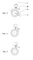
- Fig.2 simplified illustrated locking unit, has the already mentioned pawl 38, the sprocket 37, and the electric actuator 7.
- the arrow represents the direction of rotation of the rotor 10, which causes an increase of the clamping force.
- the pawl 38 is not actuated and thus the rotor 10 is not locked.
- the pawl 38 actuated by the coil 40 is momentarily energized to move the permanent magnet 39. It is possible that the pawl 38 just meets a tooth of the ring gear 37, as in Figure 3 is shown.
- the rotor 10 is not locked in this state and will turn back by the so-called activation rotation angle opposite to the direction of rotation, which would cause an increase of the application force (arrow) until the pawl 38 has reached a locking position ( Figure 4 ).
- the invention proposes that the rotor 10 after setting the required for a parking brake application force before actuation of the pawl 38 is rotated by a certain angle in that direction, which corresponds to an increase in the application force.
- the angular position of the rotor 10 is determined by the aforementioned position detection system 46 and the angular amount for further rotation of the rotor corresponds to the pitch angle ⁇ of the ring gear 37, which depends on the number of teeth of the ring gear 37.
- the pawl 38 reaches the next locking position in the direction of rotation, which causes an increase in the application force. This measure ensures that the rotor 10 is locked in a state in which the application force is at least as great as the set application force.
- the angle amount for further rotation of the rotor 10 prior to the actuation of the pawl 38 can also be determined from an additional application force amount. This is before everything makes sense and necessary if no sensor for detecting the angular position of the rotor 10 is provided.
- the rotor 10 is further rotated until the additional application force amount is set.
- This additional application force amount is chosen such that it is ensured that the pawl 38 reaches the next locking position in that direction of rotation, which causes an increase in the application force.
- the additional application force amount may be determined by a safety amount. This amount of safety takes into account the estimated or experimentally determined temperatures and thermal expansions in the disc brake as well as the stiffness of the caliper and the actuator unit, as a result of which any loss of clamping force when cooling the brake has no safety-relevant consequence.
- Another alternative according to the invention for determining the angular amount by which the rotor 10 is further rotated is the detection of the locking positions of the rotor 10.
- the position detection system 46 determines the angular position of the rotor 10 when the pawl 38 has reached a locking position.
- the angular positions of the locking positions are stored in an electronic storage medium, which may be located in the electronic control unit of the disc brake.
- the angular amount for further rotation of the rotor 10 after setting the required application force is then obtained from the comparison of the current angular position of the rotor 10 and the knowledge of the angular position of the next in the application direction locking position. By these measures, the required application force for a parking brake operation is maintained.
Landscapes
- Engineering & Computer Science (AREA)
- General Engineering & Computer Science (AREA)
- Mechanical Engineering (AREA)
- Braking Arrangements (AREA)
Claims (5)
- Procédé d'exploitation d'un frein à disque à actionnement électromécanique pour véhicule automobile avec un dispositif de frein de stationnement et une unité d'actionnement qui comporte, pour produire une force de freinage, une unité d'entraînement électromécanique (1) de laquelle au moins un élément (97) à rotation mécanique peut être verrouillé par une unité de verrouillage avec un élément de verrouillage (38), ainsi qu'avec un capteur de force de tension ou un capteur pour reconnaître la position angulaire de l'élément à rotation mécanique, caractérisé en ce que l'élément (37) à rotation mécanique est tourné encore, après réglage de la force de serrage nécessaire à un processus de freinage de stationnement, avant l'actionnement de l'élément de verrouillage (38), d'une valeur angulaire déterminée, dans la direction qui correspond à une augmentation de la force de serrage.
- Procédé selon la revendication 1, caractérisé en ce que l'unité de verrouillage est formée par un cliquet d'arrêt (38) et une roue dentée (37) dont l'angle de division détermine la valeur angulaire.
- Procédé selon la revendication 1, caractérisé en ce que la valeur angulaire est déterminée à partir d'une valeur de force de serrage supplémentaire qui est déterminée par le nombre de positions de verrouillage de l'unité de verrouillage et à partir d'une valeur de sécurité.
- Procédé selon la revendication 1, caractérisé en ce que les positions de verrouillage de l'unité de verrouillage sont déterminées à l'aide du capteur de reconnaissance de la position angulaire de l'élément à rotation mécanique, et mémorisées dans un support de mémoire électronique, et la valeur angulaire est déterminée pour continuer la rotation de l'élément à rotation mécanique, à partir de la comparaison entre la position angulaire actuelle de l'élément à rotation mécanique et les positions de verrouillage mémorisées.
- Procédé selon la revendication 3, caractérisé en ce que la valeur de sécurité est déterminée à l'aide de la rigidité de l'étrier de frein et de l'unité d'actionnement, ainsi qu'avec la température calculée ou estimée du frein à disque.
Applications Claiming Priority (4)
| Application Number | Priority Date | Filing Date | Title |
|---|---|---|---|
| DE10311750 | 2003-03-18 | ||
| DE10311750 | 2003-03-18 | ||
| DE10325414 | 2003-06-05 | ||
| DE10325414A DE10325414A1 (de) | 2003-03-18 | 2003-06-05 | Verfahren zum Betrieb einer elektromechanisch betätigbaren Scheibenbremse |
Publications (2)
| Publication Number | Publication Date |
|---|---|
| EP1460300A1 EP1460300A1 (fr) | 2004-09-22 |
| EP1460300B1 true EP1460300B1 (fr) | 2008-08-20 |
Family
ID=32826215
Family Applications (1)
| Application Number | Title | Priority Date | Filing Date |
|---|---|---|---|
| EP20040101130 Expired - Lifetime EP1460300B1 (fr) | 2003-03-18 | 2004-03-18 | Procédé de mise en service des freins de stationnement pour freins à disque d'actionnement éléctromécanique. |
Country Status (1)
| Country | Link |
|---|---|
| EP (1) | EP1460300B1 (fr) |
Cited By (1)
| Publication number | Priority date | Publication date | Assignee | Title |
|---|---|---|---|---|
| DE102020213916A1 (de) | 2020-02-14 | 2021-08-19 | Continental Teves Ag & Co. Ohg | Elektromechanischer Bremsaktuator mit integriertem EPB-Feststellbremsmodul (monostabiler Drehankermagnet) |
Families Citing this family (6)
| Publication number | Priority date | Publication date | Assignee | Title |
|---|---|---|---|---|
| KR101870635B1 (ko) * | 2011-10-24 | 2018-06-26 | 현대모비스 주식회사 | 차량용 제동장치 |
| ES2946271T3 (es) | 2018-12-06 | 2023-07-14 | Ims Gear Se & Co Kgaa | Dispositivo de bloqueo para un freno de servicio electromecánico de un vehículo de motor, freno de servicio electromecánico con un dispositivo de bloqueo de este tipo, así como vehículo de motor con un freno de servicio electromecánico de este tipo |
| DE102021209379B3 (de) * | 2021-08-26 | 2023-01-26 | Continental Automotive Technologies GmbH | Verfahren zum Betätigen eines Blockierstößels, Betätigungseinheit und Fahrzeugbremse |
| CN117698673B (zh) * | 2024-02-06 | 2024-04-12 | 北京航空航天大学 | 一种电动汽车的电子机械制动系统 |
| GB2644069A (en) * | 2024-09-13 | 2026-03-18 | Meritor Heavy Vehicle Braking Systems Uk Ltd | Actuator for a heavy vehicle foundation brake |
| GB2644067A (en) * | 2024-09-13 | 2026-03-18 | Meritor Heavy Vehicle Braking Systems Uk Ltd | An actuator |
Family Cites Families (4)
| Publication number | Priority date | Publication date | Assignee | Title |
|---|---|---|---|---|
| US6003640A (en) * | 1997-05-09 | 1999-12-21 | The B.F. Goodrich Company | Electronic braking system with brake wear measurement and running clearance adjustment |
| DE19807328C2 (de) * | 1998-02-20 | 2003-08-28 | Lucas Ind Plc | Elektromechanisch betätigbare Scheibenbremse |
| GB9823203D0 (en) * | 1998-10-24 | 1998-12-16 | Lucas Ind Plc | Parking-braking in vehicles |
| DE10054471A1 (de) * | 2000-11-03 | 2002-05-16 | Siemens Ag | Elektromechanisch betätigbare Scheibenbremse mit einer Feststellbremsanlage |
-
2004
- 2004-03-18 EP EP20040101130 patent/EP1460300B1/fr not_active Expired - Lifetime
Cited By (1)
| Publication number | Priority date | Publication date | Assignee | Title |
|---|---|---|---|---|
| DE102020213916A1 (de) | 2020-02-14 | 2021-08-19 | Continental Teves Ag & Co. Ohg | Elektromechanischer Bremsaktuator mit integriertem EPB-Feststellbremsmodul (monostabiler Drehankermagnet) |
Also Published As
| Publication number | Publication date |
|---|---|
| EP1460300A1 (fr) | 2004-09-22 |
Similar Documents
| Publication | Publication Date | Title |
|---|---|---|
| EP1530528B1 (fr) | Procede d'actionnement d'un dispositif de frein de stationnement electromecanique | |
| DE102009039271B4 (de) | Elektrische Scheibenbremse | |
| EP2195218B1 (fr) | Vis d'entraînement à billes pour un frein de véhicule à moteur et frein de véhicule à moteur | |
| EP3862235B1 (fr) | Dispositif de verrouillage d'un frein de stationnement et frein de stationnement | |
| DE19628804B4 (de) | Elektromechanisch betätigbare Scheibenbremse | |
| EP1579124B1 (fr) | Frein de stationnement commande lectrom canique | |
| DE102007053922B4 (de) | Elektronisches Einmotor-Keilbremssystem zum Verriegeln der Parkkraft | |
| WO2020207925A1 (fr) | Système de freinage d'un véhicule | |
| EP1025372B1 (fr) | Systeme de freinage pour vehicule routier | |
| DE112019005759T5 (de) | Elektromechanisches aktuatorpaket zum betätigen einer bremsanordnung | |
| DE10333092A1 (de) | Drehbetätigungsvorrichtung | |
| EP2041446B1 (fr) | Roue libre à complémentarité de forme à commande électromécanique, frein électromécanique de véhicule automobile pourvu d'une roue libre de ce type et procédé de réglage du jeu d'un frein de ce type | |
| DE102006003811B4 (de) | Steuerungsverfahren eines Bremssystems mit Motorantrieb | |
| EP1032773A1 (fr) | Frein a disque a actionnement electromecanique | |
| DE19621533A1 (de) | Elektromotorische Bremsvorrichtung | |
| EP1342018A2 (fr) | Unite d'actionnement destinee a un frein a disque pouvant etre actionne electromecaniquement | |
| EP1218646A1 (fr) | Unite d'actionnement pour un frein a disque a actionnement electromecanique | |
| EP0865977A1 (fr) | Frein à disque actionné par un moteur électrique | |
| EP1015786A1 (fr) | Frein a disque a actionnement electromecanique | |
| DE102022130191A1 (de) | Aktorbaugruppe für eine Fahrzeugbremse sowie Verfahren zum Betätigen einer Aktorbaugruppe für eine Fahrzeugbremse | |
| DE102021129955A1 (de) | Aktorbaugruppe für eine Fahrzeugbremse sowie Verfahren zur Herstellung einer Aktorbaugruppe für eine Fahrzeugbremse | |
| DE10224688A1 (de) | Verfahren zur Betätigung einer Feststellbremsanlage einer eine Betriebsbremsanlage und eine Feststellbremsanlage ausweisenden elektromechanischen Bremsanlage und elektromechanische Bremsanlage | |
| DE10015263C2 (de) | Elektromechanische Bremsvorrichtung, insbesondere für ein Kraftfahrzeug | |
| EP1460300B1 (fr) | Procédé de mise en service des freins de stationnement pour freins à disque d'actionnement éléctromécanique. | |
| DE112021002469T5 (de) | Elektrische Bremsvorrichtung |
Legal Events
| Date | Code | Title | Description |
|---|---|---|---|
| PUAI | Public reference made under article 153(3) epc to a published international application that has entered the european phase |
Free format text: ORIGINAL CODE: 0009012 |
|
| AK | Designated contracting states |
Kind code of ref document: A1 Designated state(s): AT BE BG CH CY CZ DE DK EE ES FI FR GB GR HU IE IT LI LU MC NL PL PT RO SE SI SK TR |
|
| AX | Request for extension of the european patent |
Extension state: AL LT LV MK |
|
| 17P | Request for examination filed |
Effective date: 20041027 |
|
| AKX | Designation fees paid |
Designated state(s): DE FR IT |
|
| GRAP | Despatch of communication of intention to grant a patent |
Free format text: ORIGINAL CODE: EPIDOSNIGR1 |
|
| RIN1 | Information on inventor provided before grant (corrected) |
Inventor name: MARON, CHRISTOF, DR. Inventor name: LINHOFF, PAUL Inventor name: DRUMM, STEFAN A |
|
| GRAS | Grant fee paid |
Free format text: ORIGINAL CODE: EPIDOSNIGR3 |
|
| GRAA | (expected) grant |
Free format text: ORIGINAL CODE: 0009210 |
|
| AK | Designated contracting states |
Kind code of ref document: B1 Designated state(s): DE FR IT |
|
| REF | Corresponds to: |
Ref document number: 502004007868 Country of ref document: DE Date of ref document: 20081002 Kind code of ref document: P |
|
| PLBE | No opposition filed within time limit |
Free format text: ORIGINAL CODE: 0009261 |
|
| STAA | Information on the status of an ep patent application or granted ep patent |
Free format text: STATUS: NO OPPOSITION FILED WITHIN TIME LIMIT |
|
| 26N | No opposition filed |
Effective date: 20090525 |
|
| PGFP | Annual fee paid to national office [announced via postgrant information from national office to epo] |
Ref country code: IT Payment date: 20120322 Year of fee payment: 9 |
|
| PG25 | Lapsed in a contracting state [announced via postgrant information from national office to epo] |
Ref country code: IT Free format text: LAPSE BECAUSE OF NON-PAYMENT OF DUE FEES Effective date: 20130318 |
|
| REG | Reference to a national code |
Ref country code: FR Ref legal event code: PLFP Year of fee payment: 13 |
|
| REG | Reference to a national code |
Ref country code: FR Ref legal event code: PLFP Year of fee payment: 14 |
|
| REG | Reference to a national code |
Ref country code: FR Ref legal event code: PLFP Year of fee payment: 15 |
|
| PGFP | Annual fee paid to national office [announced via postgrant information from national office to epo] |
Ref country code: PL Payment date: 20190208 Year of fee payment: 16 |
|
| REG | Reference to a national code |
Ref country code: DE Ref legal event code: R084 Ref document number: 502004007868 Country of ref document: DE |
|
| PG25 | Lapsed in a contracting state [announced via postgrant information from national office to epo] |
Ref country code: FR Free format text: LAPSE BECAUSE OF NON-PAYMENT OF DUE FEES Effective date: 20200331 |
|
| PGFP | Annual fee paid to national office [announced via postgrant information from national office to epo] |
Ref country code: DE Payment date: 20210331 Year of fee payment: 18 |
|
| REG | Reference to a national code |
Ref country code: DE Ref legal event code: R081 Ref document number: 502004007868 Country of ref document: DE Owner name: CONTINENTAL AUTOMOTIVE TECHNOLOGIES GMBH, DE Free format text: FORMER OWNER: CONTINENTAL TEVES AG & CO. OHG, 60488 FRANKFURT, DE |
|
| REG | Reference to a national code |
Ref country code: DE Ref legal event code: R119 Ref document number: 502004007868 Country of ref document: DE |
|
| PG25 | Lapsed in a contracting state [announced via postgrant information from national office to epo] |
Ref country code: DE Free format text: LAPSE BECAUSE OF NON-PAYMENT OF DUE FEES Effective date: 20221001 |