EP1460309A2 - Transmission à variation continue - Google Patents
Transmission à variation continue Download PDFInfo
- Publication number
- EP1460309A2 EP1460309A2 EP03028787A EP03028787A EP1460309A2 EP 1460309 A2 EP1460309 A2 EP 1460309A2 EP 03028787 A EP03028787 A EP 03028787A EP 03028787 A EP03028787 A EP 03028787A EP 1460309 A2 EP1460309 A2 EP 1460309A2
- Authority
- EP
- European Patent Office
- Prior art keywords
- transmission
- disc
- continuously variable
- gear
- segments
- Prior art date
- Legal status (The legal status is an assumption and is not a legal conclusion. Google has not performed a legal analysis and makes no representation as to the accuracy of the status listed.)
- Withdrawn
Links
- 230000005540 biological transmission Effects 0.000 title claims description 135
- 230000007246 mechanism Effects 0.000 claims description 4
- 230000006835 compression Effects 0.000 claims description 3
- 238000007906 compression Methods 0.000 claims description 3
- 230000001105 regulatory effect Effects 0.000 claims description 3
- 230000008878 coupling Effects 0.000 description 20
- 238000010168 coupling process Methods 0.000 description 20
- 238000005859 coupling reaction Methods 0.000 description 20
- 230000008859 change Effects 0.000 description 8
- 238000010276 construction Methods 0.000 description 5
- 230000003247 decreasing effect Effects 0.000 description 3
- 230000001419 dependent effect Effects 0.000 description 2
- 238000009434 installation Methods 0.000 description 2
- 230000001404 mediated effect Effects 0.000 description 2
- 239000002184 metal Substances 0.000 description 2
- 230000033228 biological regulation Effects 0.000 description 1
- 230000007423 decrease Effects 0.000 description 1
- 238000006073 displacement reaction Methods 0.000 description 1
- 230000000694 effects Effects 0.000 description 1
- 230000003993 interaction Effects 0.000 description 1
- 239000007788 liquid Substances 0.000 description 1
- 230000009467 reduction Effects 0.000 description 1
- 238000005096 rolling process Methods 0.000 description 1
- 238000007665 sagging Methods 0.000 description 1
- 230000035945 sensitivity Effects 0.000 description 1
- 230000007480 spreading Effects 0.000 description 1
Images


Classifications
-
- F—MECHANICAL ENGINEERING; LIGHTING; HEATING; WEAPONS; BLASTING
- F16—ENGINEERING ELEMENTS AND UNITS; GENERAL MEASURES FOR PRODUCING AND MAINTAINING EFFECTIVE FUNCTIONING OF MACHINES OR INSTALLATIONS; THERMAL INSULATION IN GENERAL
- F16H—GEARING
- F16H55/00—Elements with teeth or friction surfaces for conveying motion; Worms, pulleys or sheaves for gearing mechanisms
- F16H55/32—Friction members
- F16H55/52—Pulleys or friction discs of adjustable construction
- F16H55/54—Pulleys or friction discs of adjustable construction of which the bearing parts are radially adjustable
-
- B—PERFORMING OPERATIONS; TRANSPORTING
- B62—LAND VEHICLES FOR TRAVELLING OTHERWISE THAN ON RAILS
- B62M—RIDER PROPULSION OF WHEELED VEHICLES OR SLEDGES; POWERED PROPULSION OF SLEDGES OR SINGLE-TRACK CYCLES; TRANSMISSIONS SPECIALLY ADAPTED FOR SUCH VEHICLES
- B62M9/00—Transmissions characterised by use of an endless chain, belt, or the like
- B62M9/04—Transmissions characterised by use of an endless chain, belt, or the like of changeable ratio
- B62M9/06—Transmissions characterised by use of an endless chain, belt, or the like of changeable ratio using a single chain, belt, or the like
- B62M9/08—Transmissions characterised by use of an endless chain, belt, or the like of changeable ratio using a single chain, belt, or the like involving eccentrically- mounted or elliptically-shaped driving or driven wheel; with expansible driving or driven wheel
-
- F—MECHANICAL ENGINEERING; LIGHTING; HEATING; WEAPONS; BLASTING
- F16—ENGINEERING ELEMENTS AND UNITS; GENERAL MEASURES FOR PRODUCING AND MAINTAINING EFFECTIVE FUNCTIONING OF MACHINES OR INSTALLATIONS; THERMAL INSULATION IN GENERAL
- F16H—GEARING
- F16H9/00—Gearings for conveying rotary motion with variable gear ratio, or for reversing rotary motion, by endless flexible members
- F16H9/02—Gearings for conveying rotary motion with variable gear ratio, or for reversing rotary motion, by endless flexible members without members having orbital motion
- F16H9/04—Gearings for conveying rotary motion with variable gear ratio, or for reversing rotary motion, by endless flexible members without members having orbital motion using belts, V-belts, or ropes
- F16H9/10—Gearings for conveying rotary motion with variable gear ratio, or for reversing rotary motion, by endless flexible members without members having orbital motion using belts, V-belts, or ropes engaging a pulley provided with radially-actuatable elements carrying the belt
Definitions
- the invention relates to a continuously variable transmission with input and output shaft, as well as one or more pulley-receiving disks (gear disks), the diameter of which can be varied continuously.
- Infinitely variable gearbox are gearboxes with continuously variable output speed, which are mostly designed as traction mechanisms or liquid gearboxes. They optimally meet the requirements of vehicle and machine drives because they allow the speeds to be adapted to the respective operating conditions. By continuously changing the gear ratio, these gearboxes reduce the maximum turning power from the engine. V-belt Vario transmissions are also used for small cars and scooters. This leads to a strong change in the gear ratios, especially when starting off and braking.
- a sprocket change transmission (DE-PS 663180) and a V-belt variable transmission (DE 196 09 750 C2) are known from the prior art.
- a lateral, load-proportional coupling of the traction means and a control of the running circuit via coupling sleeves connected by cam disks with a forward and backward displacement of the coupling point are provided.
- a non-elastic, metal hinge is used as a traction device.
- the coupling means are designed as radially and axially movable metal clamping jaws. Due to the low coefficient of friction A high contact pressure must be generated between the traction device and the hinge in order to couple securely.
- Rolling elements are installed in the cams to prevent the coupling mechanism from becoming self-locking and from freeing up. With this device, only a small part of the traction force can be used to generate the coupling force, so that tangential slippage between the coupling means and traction device inevitably occurs during the entry and exit.
- the infinitely variable change in the gear ratio is also achieved by an infinitely variable change in the traction mechanism radius on at least one drive double pulley.
- the force transmission between the traction means and the drive double disks is also achieved here by coupling means acting laterally on the traction means.
- the coupling means arranged on the face plates are tangentially and radially movable. They are self-supporting or self-locking to achieve the load-dependent power transmission under load and disconnect automatically at the outlet point.
- the coupling means convert the tangential and / or radial belt movements and forces into axial spreading movements and thus into lateral pressure forces in the form of an axial contact force on the belt flank.
- the radial guidance of the traction device is achieved in this transmission by a feeler roller attached to the control arm, which rests on the inside of the traction device and, depending on the position of the control arm, specifies the traction device radius, and by control pins that can be moved in the axial direction.
- the control pins guide the traction device when changing the traction device radius, but are not involved in the power transmission mediated by the traction device.
- this control includes a variety of wear parts. For example, 10 coupling means per drive pulley are suggested for good concentricity. In addition to the wear sensitivity of the coupling means, it is also disadvantageous that they have to be set up with a considerable amount of time.
- the invention is based on the problem of the construction of continuously variable transmissions for different areas of application, the transmission disks of which are continuously variable in diameter, so that a continuous change in the gear ratio is possible.
- lateral coupling means which act on the traction means with clamping force should be dispensed with entirely.
- the object is achieved on the basis of a generic variable transmission (DE 196 09 750 C2), with coupling means acting laterally on the traction means, in that the transmission disks are constructed in segments and have a central bore to which a control element with a conical bearing that is movably mounted in the axial direction is attached External shape is present, the segments are continuously movable in the radial direction, the translation-effective diameter of each transmission disc can be regulated by displacing the control element in the axial direction while widening the central bore between the segments, the segments being guided and driven on both sides in the axial direction.
- the main idea of the invention is that the traction-circle radius of a gear disc of segment-like construction can be infinitely adjusted by a control element with a conical outer shape that is movably mounted in the axial direction, the segments and thus the disc diameter being widened at higher speeds. This expansion is caused by the control segment that rests with spring pressure.
- the segments of each transmission disk are guided on both sides below the outer area serving to receive the traction means in the axial direction, by means of two guide rings which are rigidly connected to the drive shaft.
- the segments of the gear disc, the control element and the guide rings which are rigidly connected to the axle on both sides form a freely rotatable unit together with appropriate storage.
- the shape of the segments is designed such that they are guided on their narrow side by their movement in the radial direction by rollers which are positioned on a concentric circle between the segments.
- Each segment is provided with an elongated hole aligned in the radial direction, through which a locking pin is anchored in the guide rings lying on the side. While the minimum traction circle radius of the gear disc can be adjusted by removing the control element from the central hole, the locking pin limits the maximum expansion of the individual segments when the control element is moved in the axial direction.
- the widened segments lie on the conical outside of the control element. Since the control element with constant contact pressure, which is created by a helical compression spring fastened in the hollow cylindrical drive shaft, rests laterally at the lower end of the segments, the transmission disc expands with increasing speeds. This is associated with a continuous change in the gear ratio.
- the simplest embodiment of a transmission using the transmission disc according to the invention is obtained by the Gear disc with a constant diameter in diameter and attached to a parallel output shaft connected by traction means.
- the corresponding output shaft could, for example, be the hub on the rear wheel of a bicycle.
- the traction device is guided by an additionally attached tensioning roller with slight tension.
- the segmented gear disc can be used for the modular construction of coupled gearboxes if it is attached to the input and output shafts.
- An inventive single-coupled and an inventive double-coupled continuously variable transmission are discussed below.
- a single-coupled, infinitely variable transmission is obtained using two transmission disks, which are fastened on a drive means connected to each other in parallel with the drive means and output shaft.
- Both the gear disc (drive disc) connected to the drive shaft and the gear disc (output disc) connected to the output shaft are provided with a control element. It is crucial for the control of the transmission that the control element on the drive shaft is mechanically coupled to the control element on the output shaft by a lever rotatably fixed between the axes.
- the transmission is installed in a housing that also forms the transmission frame.
- an additional disc is attached outside the housing, which has a constant diameter and is connected to the output shaft of the transmission.
- Double-coupled continuously variable transmission is
- the suitability of the transmission disc according to the invention for the modular construction of continuously variable transmissions is clearly expressed.
- two transmission disks which are directly opposite each other in pairs are coupled in terms of movement by means of traction means on two shafts which are constantly spaced apart and arranged in parallel.
- the first gear disc connected to the drive shaft is referred to as a drive pulley and corresponds in structure to the gear pulley according to the invention.
- Another gear washer is attached to the parallel transmission shaft.
- These two disks are referred to as transmission disks and also correspond in structure to the transmission disk according to the invention.
- the translation disks are rigidly connected to the translation shaft.
- the control elements of the transmission disks also have a conical outer shape and have a central bore on their flared side and are rigidly connected to one another on this flared side by a hollow cylinder.
- This unit created by the hollow cylinder is movably supported on the transmission shaft and is referred to as the control unit of the transmission shaft. Due to the constant spacing of the control elements on the transmission shaft, the transmission disks are dependent on one another in the setting of their translation-effective diameters.
- the double coupling of the gearbox now comes about because the movably mounted control element of the drive pulley and the control unit movably connected to the translation axis are coupled to one another by a lever which is rotatably fixed between the axes. If there is an expansion of the drive pulley at higher speeds, the axial movement of the control element of the drive pulley in the direction of the segments of the drive pulley is transmitted to the control unit of the transmission shaft by the lever fastened between the axles. Due to the movement coupling of the control elements, the expansion of the drive pulley is associated with a reduction in the diameter on the opposite transmission pulley, which is connected to the drive pulley by traction means.
- the movement of the control unit also has an effect on the diameter of the second transmission disk: if the diameter of the transmission disk connected to the drive disk is regulated to smaller diameters, the diameter of the second transmission disk is inevitably increased. Since both transmission discs are rigidly connected to each other on the transmission shaft, they have the same speed, but very different outside diameters.
- the coupling is such that with a maximum outer diameter of the drive disk, the second transmission disk also reaches its maximum outer diameter and thus generates the maximum speeds on the driven disk, which is constant in diameter and freely supported on the drive shaft, by means of a traction device connection.
- a tensioning roller is in contact with the traction device with slight tension.
- the gear disk which is freely supported on the drive shaft and has a constant diameter, is rigidly connected outside the housing to a further disk which is also constant in diameter.
- the traction means used to establish the operative connection between the transmission pulleys or between the transmission and driven pulleys are preferably V-belts or flat belts.
- the gear disk according to the invention and the gear shapes based thereon are also suitable for driving bicycles.
- the simplest form of a corresponding bicycle transmission is characterized in that a transmission disc according to the invention is connected to the pedals as a drive disc and is connected by traction means to a disc fixed on the hub of the rear wheel and of constant diameter.
- a tension roller with light tension is applied to the traction device.
- a simply coupled, continuously adjustable bicycle transmission can be constructed in two different ways with the transmission disc according to the invention.
- a transmission disk according to the invention is connected as a drive disk to the pedals of the two-wheel.
- a second identical gear disc is rigidly connected to the hub of the rear wheel via its shaft. Because the frame of the bicycle would be a hindrance, the control elements of the two transmission disks are in this case not connected by a lever, but by shift cables.
- the second option for installing a simply coupled, continuously variable transmission on the bicycle is to use the described, simply coupled, continuously variable transmission.
- the pedals are attached to the drive shaft of the gearbox and those outside the gearbox the disc is connected to the hub of the rear wheel by means of traction.
- a bicycle with a double-coupled continuously variable transmission can be obtained by the corresponding installation of the double-coupled continuously variable transmission according to the invention.
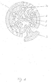
- FIG. 1 shows a gear disc 1 made up of six segments 3.
- the shape of the segments 3 is designed such that when they move in the radial direction on their narrow side they are guided by rollers 4 which are positioned on a concentric circle between the segments 3.
- Each segment 3 is provided with an elongated hole 6 oriented in the radial direction, through which a locking pin 5 anchored in the laterally adjacent guide rings 8a, 8b.
- the locking pin 5 limits the widening of the segments 3 in the radial direction when the control element 7a movable in the axial direction widens the segments 3 at the central bore 2.
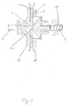
- FIG. 2 shows a gear disk 1a according to the invention in cross-section with the smallest possible disk diameter.
- the segments of the gear disk 1a are guided on both sides below the area serving to receive the traction means 12 in the axial direction, through two guide rings 8a, which are rigidly connected to the drive shaft 9.
- a control element 7a with a conical outer shape so that the tapered end abuts the central bore 2 of the gear disc 1a.
- the control element 7a is pressed by a helical compression spring 10 with constant contact pressure against the segments 3 of the gear disk 1a.
- a single-coupled, continuously variable transmission is shown in cross section in FIG.
- a gear disk 1 a according to the invention is connected to the drive shaft 9.
- a second gear disc 1 b according to the invention is fastened on the output shaft 11.
- the two gear discs are operatively connected by a traction means 12.
- the segments of the second gear disc 1b are widened to the maximum possible diameter by the conical control element 7b, while the gear disc 1a shows its smallest possible diameter.
- the movements of the control elements 7a and 7b are coupled to one another by a lever 13a. If higher drive speeds on the drive shaft 9 lead to an expansion of the gear disk 1a, the control element 7b is simultaneously retracted, the diameter of the gear disk 1b decreasing. Due to this coupling, mediated by the lever 13a, there is a continuous change in the gear ratio.
- a disk 16a of constant diameter is rigidly connected to the output shaft for further power transmission.
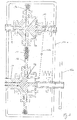
- FIG. 4 shows the cross section through a double-coupled, continuously variable transmission.
- this gear At the construction of this gear are three gear discs 1a, 1b bund 1c involved.
- the first gear disk 1a connected to the drive shaft 9 is referred to as the drive disk.
- the two transmission disks 1b and 1c fastened on the parallel transmission shaft are referred to as transmission disks.
- the translation disks 1b, 1c are rigidly connected to the translation shaft 17.
- the control elements 7b, 7c have a central bore 19a, 19b on their expanded side and are rigidly connected to one another at this point by a hollow cylinder 20. This unit is movably mounted on the transmission shaft and is referred to as the control unit 21 of the transmission shaft.
- the double coupling of the gearbox is achieved in that the movably mounted control element 7a of the drive pulley 1a and the control unit 21 movably connected to the transmission axis 17 are coupled to one another by a lever 13b rotatably fixed between the axes.
- the second transmission disc 1c is connected by a traction means 12 to an output disc 18 which is freely supported on the drive shaft 9 and has a constant diameter.
- the disk 18 is rigidly connected outside the housing 14b, which also represents the transmission frame, to a further disk 16b, which is also constant in diameter.
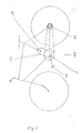
- FIG. 5 schematically shows the simplest form of a continuously variable bicycle transmission that can be achieved with the transmission disc according to the invention.
- the pedals 22 of the bicycle are rigidly connected to the axis 9 of the gear disc 1a.
- the variable-diameter gear disk 1a is connected by means of traction to a disk attached to the hub of the rear wheel 23.
- a tensioning roller 24 is applied to the traction device with slight tension.
- FIG 6 the use of the double-coupled continuously variable transmission as a bicycle transmission is shown schematically.
- the drive shaft 9 is rigidly connected to the pedals 22.
- the gear housing 14b is oriented during installation in the bicycle so that the long side of the transmission shaft 17 points in the direction of the bicycle saddle.
- the disk 16b which is constant in diameter for the transmission of force and which is constant in diameter, is connected by traction means to a disk fastened to the hub 23 and also constant in diameter.
Landscapes
- Engineering & Computer Science (AREA)
- General Engineering & Computer Science (AREA)
- Mechanical Engineering (AREA)
- Chemical & Material Sciences (AREA)
- Combustion & Propulsion (AREA)
- Transportation (AREA)
- Friction Gearing (AREA)
- Transmissions By Endless Flexible Members (AREA)
- Transmission Devices (AREA)
Applications Claiming Priority (2)
| Application Number | Priority Date | Filing Date | Title |
|---|---|---|---|
| DE10311432 | 2003-03-15 | ||
| DE2003111432 DE10311432A1 (de) | 2003-03-15 | 2003-03-15 | Stufenlos einstellbares Getriebe |
Publications (2)
| Publication Number | Publication Date |
|---|---|
| EP1460309A2 true EP1460309A2 (fr) | 2004-09-22 |
| EP1460309A3 EP1460309A3 (fr) | 2006-08-02 |
Family
ID=32797920
Family Applications (1)
| Application Number | Title | Priority Date | Filing Date |
|---|---|---|---|
| EP03028787A Withdrawn EP1460309A3 (fr) | 2003-03-15 | 2003-12-13 | Transmission à variation continue |
Country Status (2)
| Country | Link |
|---|---|
| EP (1) | EP1460309A3 (fr) |
| DE (1) | DE10311432A1 (fr) |
Cited By (8)
| Publication number | Priority date | Publication date | Assignee | Title |
|---|---|---|---|---|
| EP2988022A3 (fr) * | 2014-08-05 | 2016-03-02 | Deere & Company | Ensemble d'entraînement par courroie à vitesse variable |
| CN106218240A (zh) * | 2015-06-02 | 2016-12-14 | 富士通电子零件有限公司 | 打印装置 |
| NL2017150B1 (nl) * | 2016-07-11 | 2018-01-17 | Drive Tech Holland Ltd | Transmissie en voertuig voorzien van een dergelijke transmissie. |
| CN110762172A (zh) * | 2018-07-25 | 2020-02-07 | 重庆宗申无级变速传动有限公司 | 一种三轴调速的锥盘式无级变速器 |
| CN111448405A (zh) * | 2017-07-13 | 2020-07-24 | 先进传输系统控股有限公司 | 皮带轮和传动系统 |
| US10753456B2 (en) | 2016-04-20 | 2020-08-25 | Ge Avio S.R.L. | Oil transfer unit for transferring oil between a stationary part and a rotating part |
| CN113483077A (zh) * | 2021-07-29 | 2021-10-08 | 刘小梅 | 一种机械带轮及其工作方法 |
| WO2024261051A1 (fr) * | 2023-06-23 | 2024-12-26 | Battaggia Stefano | Variateur de vitesse |
Citations (2)
| Publication number | Priority date | Publication date | Assignee | Title |
|---|---|---|---|---|
| DE663180C (de) | 1936-06-28 | 1938-07-30 | Hofmann Walter | Kettenraederwechselgetriebe mit stufenloser Regelung |
| DE19609750C2 (de) | 1996-03-13 | 1998-07-30 | Edgar Loehr | Stufenlos einstellbares Getriebe |
Family Cites Families (13)
| Publication number | Priority date | Publication date | Assignee | Title |
|---|---|---|---|---|
| DE114379C (fr) * | ||||
| GB191125516A (en) * | 1912-05-16 | 1913-01-16 | Dron & Lawson Ltd | Improvements in and relating to Variable Speed Gears. |
| US1374439A (en) * | 1919-10-25 | 1921-04-12 | Morris I Kopple | Variable-speed device |
| GB149723A (en) * | 1919-11-21 | 1920-08-26 | Henry Barclay Allan | An improved variable speed gear |
| DE634643C (de) * | 1933-07-09 | 1936-09-01 | Kamill Huebner | Wechselgetriebe mit Keilriemen, Seilen o. dgl. |
| FR1098110A (fr) * | 1954-01-06 | 1955-07-18 | Perfectionnements apportés aux changements de vitesse continus | |
| NL6507654A (fr) * | 1965-06-15 | 1966-12-16 | ||
| ES505342A0 (es) * | 1981-09-09 | 1984-05-16 | Ybern Miro Pedro | Perfeccionamientos en organos variadores de relacion de transmision |
| US4842569A (en) * | 1987-11-16 | 1989-06-27 | Recreational Accessoried Corporation | Bicycle transmission having infinitely variable drive ratio |
| DE3914902A1 (de) * | 1989-05-05 | 1990-11-08 | Ernst Wollenschneider | Fahrradantrieb |
| GB2239063A (en) * | 1989-12-07 | 1991-06-19 | Fraser Milne | Variable speed drive comprising a pulley with radially movable parts |
| US5492506A (en) * | 1994-10-14 | 1996-02-20 | Lorance; R. Dennis | Continuously variable pulley |
| DE4446886A1 (de) * | 1994-12-27 | 1996-07-04 | Samy Dipl Ing Kamal | Stufenloses Zugmittelgetriebe mit verstellbaren Riemenscheiben oder Kettenräder |
-
2003
- 2003-03-15 DE DE2003111432 patent/DE10311432A1/de not_active Withdrawn
- 2003-12-13 EP EP03028787A patent/EP1460309A3/fr not_active Withdrawn
Patent Citations (2)
| Publication number | Priority date | Publication date | Assignee | Title |
|---|---|---|---|---|
| DE663180C (de) | 1936-06-28 | 1938-07-30 | Hofmann Walter | Kettenraederwechselgetriebe mit stufenloser Regelung |
| DE19609750C2 (de) | 1996-03-13 | 1998-07-30 | Edgar Loehr | Stufenlos einstellbares Getriebe |
Cited By (11)
| Publication number | Priority date | Publication date | Assignee | Title |
|---|---|---|---|---|
| EP2988022A3 (fr) * | 2014-08-05 | 2016-03-02 | Deere & Company | Ensemble d'entraînement par courroie à vitesse variable |
| CN106218240A (zh) * | 2015-06-02 | 2016-12-14 | 富士通电子零件有限公司 | 打印装置 |
| CN106218240B (zh) * | 2015-06-02 | 2018-11-27 | 富士通电子零件有限公司 | 打印装置 |
| US10753456B2 (en) | 2016-04-20 | 2020-08-25 | Ge Avio S.R.L. | Oil transfer unit for transferring oil between a stationary part and a rotating part |
| NL2017150B1 (nl) * | 2016-07-11 | 2018-01-17 | Drive Tech Holland Ltd | Transmissie en voertuig voorzien van een dergelijke transmissie. |
| WO2018012966A1 (fr) * | 2016-07-11 | 2018-01-18 | Drive Technology Holland Ltd. | Transmission et véhicule pourvu d'une telle transmission |
| US11326671B2 (en) | 2016-07-11 | 2022-05-10 | Drive Technology Holland Ltd. | Transmission and vehicle provided with such a transmission |
| CN111448405A (zh) * | 2017-07-13 | 2020-07-24 | 先进传输系统控股有限公司 | 皮带轮和传动系统 |
| CN110762172A (zh) * | 2018-07-25 | 2020-02-07 | 重庆宗申无级变速传动有限公司 | 一种三轴调速的锥盘式无级变速器 |
| CN113483077A (zh) * | 2021-07-29 | 2021-10-08 | 刘小梅 | 一种机械带轮及其工作方法 |
| WO2024261051A1 (fr) * | 2023-06-23 | 2024-12-26 | Battaggia Stefano | Variateur de vitesse |
Also Published As
| Publication number | Publication date |
|---|---|
| EP1460309A3 (fr) | 2006-08-02 |
| DE10311432A1 (de) | 2004-09-23 |
Similar Documents
| Publication | Publication Date | Title |
|---|---|---|
| DE19725834A1 (de) | Stufenlos schaltbares automatisches Getriebe für ein Fahrzeug | |
| DE19530615C2 (de) | Kegelscheiben-Umschlingungsgetriebe | |
| EP0947732A1 (fr) | Transmission à variation continue à poulies et courroie | |
| DE60015738T2 (de) | Stufenloses Getriebe mit Schmierungsdüsen in Abtriebsrichtung auf eine Radialposition maximaler Leistungsübertragung des Riemens | |
| DE4321588C2 (de) | Stufenloses Reibrollengetriebe | |
| EP1460309A2 (fr) | Transmission à variation continue | |
| EP1604133A1 (fr) | Unite modulaire de transmission, notamment de transmission multi-etagee | |
| DE19643437C2 (de) | Stufenlos verstellbares Getriebe | |
| DE3107255A1 (de) | "ketten- bzw. riementrieb" | |
| DE112009003633T5 (de) | Stufenlos variables Reibgetriebe | |
| DE10222520A1 (de) | Automatgetriebe mit wenigstens zwei Kegelscheibensätzen | |
| DE102020103472B4 (de) | Fahrzeuggetriebe mit wenigstens einer CVT-Getriebestufe | |
| DE4435779A1 (de) | Stufenloses Getriebe | |
| EP0084160B1 (fr) | Mécanisme d'entraînement à chaine | |
| DE10010741A1 (de) | Stufenlos verstellbares Getriebe | |
| WO1996020360A1 (fr) | Transmission sans fin a element de traction, munie de poulies ou de roues a chaine reglables | |
| DE19609750C2 (de) | Stufenlos einstellbares Getriebe | |
| DE3600627C1 (en) | Planetary friction gear system with elastically deformed planet gears and infinitely variable rpm control | |
| EP1384017B1 (fr) | Transmission par friction a reglage continu | |
| DE60313463T2 (de) | Stufenloses Getriebe | |
| DE10361332B4 (de) | Variatorscheibe und Variator für ein Toroidgetriebe | |
| DE19633274A1 (de) | Selbsttätig stufenlos regelndes Zugmittelgetriebe | |
| EP1506357B1 (fr) | Transmission automatique a variateur pourvu d'au moins deux jeux de poulies coniques | |
| DE10346894B3 (de) | Stufenloses Getriebe | |
| DE2263229B2 (de) | Stufenlos einstellbares Kegelscheibenumschlingungsgetriebe mit drehmomentabhängiger Anpreßung an beiden Kegelscheiben |
Legal Events
| Date | Code | Title | Description |
|---|---|---|---|
| PUAI | Public reference made under article 153(3) epc to a published international application that has entered the european phase |
Free format text: ORIGINAL CODE: 0009012 |
|
| AK | Designated contracting states |
Kind code of ref document: A2 Designated state(s): AT BE BG CH CY CZ DE DK EE ES FI FR GB GR HU IE IT LI LU MC NL PT RO SE SI SK TR |
|
| AX | Request for extension of the european patent |
Extension state: AL LT LV MK |
|
| PUAL | Search report despatched |
Free format text: ORIGINAL CODE: 0009013 |
|
| AK | Designated contracting states |
Kind code of ref document: A3 Designated state(s): AT BE BG CH CY CZ DE DK EE ES FI FR GB GR HU IE IT LI LU MC NL PT RO SE SI SK TR |
|
| AX | Request for extension of the european patent |
Extension state: AL LT LV MK |
|
| AKX | Designation fees paid | ||
| STAA | Information on the status of an ep patent application or granted ep patent |
Free format text: STATUS: THE APPLICATION IS DEEMED TO BE WITHDRAWN |
|
| 18D | Application deemed to be withdrawn |
Effective date: 20070203 |
|
| REG | Reference to a national code |
Ref country code: DE Ref legal event code: 8566 |