EP1460330A2 - Dispositif de suspension pour un capot de protection de machine de longueur variable - Google Patents
Dispositif de suspension pour un capot de protection de machine de longueur variable Download PDFInfo
- Publication number
- EP1460330A2 EP1460330A2 EP04005394A EP04005394A EP1460330A2 EP 1460330 A2 EP1460330 A2 EP 1460330A2 EP 04005394 A EP04005394 A EP 04005394A EP 04005394 A EP04005394 A EP 04005394A EP 1460330 A2 EP1460330 A2 EP 1460330A2
- Authority
- EP
- European Patent Office
- Prior art keywords
- roller
- longitudinal slot
- suspension according
- roller suspension
- sliding
- Prior art date
- Legal status (The legal status is an assumption and is not a legal conclusion. Google has not performed a legal analysis and makes no representation as to the accuracy of the status listed.)
- Withdrawn
Links
Images


Classifications
-
- B—PERFORMING OPERATIONS; TRANSPORTING
- B23—MACHINE TOOLS; METAL-WORKING NOT OTHERWISE PROVIDED FOR
- B23Q—DETAILS, COMPONENTS, OR ACCESSORIES FOR MACHINE TOOLS, e.g. ARRANGEMENTS FOR COPYING OR CONTROLLING; MACHINE TOOLS IN GENERAL CHARACTERISED BY THE CONSTRUCTION OF PARTICULAR DETAILS OR COMPONENTS; COMBINATIONS OR ASSOCIATIONS OF METAL-WORKING MACHINES, NOT DIRECTED TO A PARTICULAR RESULT
- B23Q11/00—Accessories fitted to machine tools for keeping tools or parts of the machine in good working condition or for cooling work; Safety devices specially combined with or arranged in, or specially adapted for use in connection with, machine tools
- B23Q11/08—Protective coverings for parts of machine tools; Splash guards
- B23Q11/085—Flexible coverings, e.g. coiled-up belts
-
- B—PERFORMING OPERATIONS; TRANSPORTING
- B23—MACHINE TOOLS; METAL-WORKING NOT OTHERWISE PROVIDED FOR
- B23Q—DETAILS, COMPONENTS, OR ACCESSORIES FOR MACHINE TOOLS, e.g. ARRANGEMENTS FOR COPYING OR CONTROLLING; MACHINE TOOLS IN GENERAL CHARACTERISED BY THE CONSTRUCTION OF PARTICULAR DETAILS OR COMPONENTS; COMBINATIONS OR ASSOCIATIONS OF METAL-WORKING MACHINES, NOT DIRECTED TO A PARTICULAR RESULT
- B23Q11/00—Accessories fitted to machine tools for keeping tools or parts of the machine in good working condition or for cooling work; Safety devices specially combined with or arranged in, or specially adapted for use in connection with, machine tools
- B23Q11/08—Protective coverings for parts of machine tools; Splash guards
- B23Q11/0816—Foldable coverings, e.g. bellows
-
- F—MECHANICAL ENGINEERING; LIGHTING; HEATING; WEAPONS; BLASTING
- F16—ENGINEERING ELEMENTS AND UNITS; GENERAL MEASURES FOR PRODUCING AND MAINTAINING EFFECTIVE FUNCTIONING OF MACHINES OR INSTALLATIONS; THERMAL INSULATION IN GENERAL
- F16P—SAFETY DEVICES IN GENERAL; SAFETY DEVICES FOR PRESSES
- F16P3/00—Safety devices acting in conjunction with the control or operation of a machine; Control arrangements requiring the simultaneous use of two or more parts of the body
- F16P3/02—Screens or other safety members moving in synchronism with members which move to and fro
Definitions
- the invention relates to a roller suspension for a vertically suspended, in the horizontal direction variable in length machine protection cover with a horizontal roller guide in the form of a continuous longitudinal slot having a metallic box profile and with roller holders, each having an elongated, flat, metallic retaining web, at its upper end on both sides each a rotatable roller is held and the lower end of which can be connected to an upper edge of a bellows, the retaining web engages with play through the longitudinal slot and the two rollers roll adjacent to it on the inside of the profile.
- roller holders With such a roller suspension for partly very quickly moving machine protective covers, such as bellows, there is the problem that the roller holders not only carry out the intended longitudinal movements in the longitudinal direction of the roller guide, but also from the variable-length protective cover to considerable lateral displacement and tilting movements as well as pivoting be forced around vertical axes. This leads to mutual material contact between the holding bars of the roll holder and the lateral boundaries of the longitudinal slot of the roll suspension and thus to corresponding ones Signs of wear and annoying noises. Slightly movement-preventing canting of the holding webs can also occur in the longitudinal slot of the roller guide.
- the longitudinal slot should not have a slot width that is too large due to the guiding function of the roller guide, on the other hand, however, this slot width should not be too small, so that sufficient movement play, given by the protective cover, is possible and high speeds with acceptable movement resistance as well as limited wear and noise development are permitted can be.
- the present invention has for its object to provide a roller suspension of the type mentioned with simple measures so that while avoiding the disadvantages described, large travel speeds with good guiding function, low noise and long-term operation are possible without risk of movement blocking.
- a roller suspension of the type mentioned in the preamble of claim 1 is characterized according to the invention by the features listed in the characterizing part of this claim, namely in that the metal surfaces of the holding web pointing to the edges of the longitudinal slot and / or those to the holding web pointing metallic edges of the longitudinal slot of the profile are formed with a sliding layer made of an abrasion-resistant sliding material.
- the outer sides of the holding web can have a full-surface sliding layer, it is sufficient according to claim 3 to design the sliding layer of the holding web in the area of the longitudinal slot only partially.
- the sliding layer can be designed as a film-like or plate-shaped planking, which according to the development of claim 5 can be attached by an adhesive or riveted connection.
- the sliding layer can consist of various sliding materials that are sufficiently abrasion-resistant and have good sliding and noise reduction properties.
- L-shaped cladding which is easy to attach and glue, has also proven itself as sliding layers for the longitudinal slot.
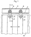
- a roller guide 10 is designed as a metal box profile provided with an underside longitudinal slot 12, which is attached in a horizontal orientation to a machine or in a room.
- a roll holder 14 has a flat, elongated retaining web 16. At the upper end in the working position there is a roller bearing pin 19 projecting on both sides with rollers 18 located thereon Machine protective cover 28 movable in the horizontal double arrow direction and variable in length, such as a Bellows or other protective cover, can be attached on the top.
- the holding webs 16 of a plurality of roller holders 14 engage through the longitudinal slot 12 of the roller guide 10 in such a way that the rollers 18 are supported on the inner edges of the box section and roll off.
- the rollers 18 can have races 22 made of plastic, POM (polyacetal) or a particularly suitable metal, so that a quiet, gentle, long-lasting operating procedure can be achieved.
- the rollers can also have ball bearings.
- the machine protective cover 28 is designed in the form of a bellows, especially in the case of rapid longitudinal movements, this forces strong movements of the roller holder 14 which deviate from a pure longitudinal movement, such as lateral displacements and swiveling and twisting or tilting movements about a vertical axis , This leads to strong contact between the retaining web 16 of the roller holder 14 penetrating the longitudinal slot 12 and the lateral boundaries of the longitudinal slot 12. While this causes strong friction and wear and tear, sometimes even movement-blocking canting, and considerable noise pollution, this will occur in the prior art Prevented within the scope of the present invention by sliding layers 24 and 26 consisting of suitable sliding materials.
- the sliding layers 24 can cover the holding web 16 on all sides or even only on the opposing surfaces facing the edges of the longitudinal slot 12. In this case, however, it is sufficient to cover only the areas of the holding web 16 that are directly adjacent to the edges of the longitudinal slot 12, that is to say they can come into contact with them.
- FIG. 6 it is also possible according to FIG. 6 to provide the inner boundaries of the longitudinal slot 12 with a sliding layer 26. This can be done, for example, that L-shaped profiles made of a sliding material are fitted and glued, which limit the longitudinal slots 12 on the inside and extend around the lower edge thereof. It is sufficient that the L-shaped profiles are only attached to the underside of the box profile, as stuck on.
- sliding materials can be used for the sliding layers 24 and 26, for example film-like or plate-shaped solid sliding materials made of PE (polyethylene), Teflon, POM (polyacetal) or brushable, hardenable sliding pastes, such as a sliding paste based on diamond. It is always important that the sliding material has very good sliding properties and great abrasion resistance and has a noise-reducing effect. Furthermore, it is possible to additionally lubricate or oil the sliding material used, which can be done, for example, by a constant or repetitive machine-side oil supply.
Landscapes
- Engineering & Computer Science (AREA)
- Mechanical Engineering (AREA)
- General Engineering & Computer Science (AREA)
- Road Paving Machines (AREA)
- Rolls And Other Rotary Bodies (AREA)
- Bearings For Parts Moving Linearly (AREA)
Applications Claiming Priority (2)
| Application Number | Priority Date | Filing Date | Title |
|---|---|---|---|
| DE20304672U DE20304672U1 (de) | 2003-03-21 | 2003-03-21 | Rollenaufhängung für eine längenveränderliche Maschinen-Schutzabdeckung |
| DE20304672U | 2003-03-21 |
Publications (2)
| Publication Number | Publication Date |
|---|---|
| EP1460330A2 true EP1460330A2 (fr) | 2004-09-22 |
| EP1460330A3 EP1460330A3 (fr) | 2005-04-06 |
Family
ID=7981048
Family Applications (1)
| Application Number | Title | Priority Date | Filing Date |
|---|---|---|---|
| EP04005394A Withdrawn EP1460330A3 (fr) | 2003-03-21 | 2004-03-06 | Dispositif de suspension pour un capot de protection de machine de longueur variable |
Country Status (2)
| Country | Link |
|---|---|
| EP (1) | EP1460330A3 (fr) |
| DE (1) | DE20304672U1 (fr) |
Families Citing this family (3)
| Publication number | Priority date | Publication date | Assignee | Title |
|---|---|---|---|---|
| DE20304672U1 (de) * | 2003-03-21 | 2003-06-05 | HEMA Maschinen- und Apparateschutz GmbH, 63500 Seligenstadt | Rollenaufhängung für eine längenveränderliche Maschinen-Schutzabdeckung |
| EP2085179B1 (fr) * | 2008-02-01 | 2012-07-18 | Eitec Führungsbahnschutz-Systeme GmbH | Recouvrement flexible |
| DE202023105357U1 (de) | 2023-09-15 | 2024-12-17 | MöllerWerke GmbH | Führungselement für eine Schutzabdeckung sowie Schutzabdeckung und entsprechendes Schutzabdeckungssystem |
Family Cites Families (8)
| Publication number | Priority date | Publication date | Assignee | Title |
|---|---|---|---|---|
| US1855037A (en) * | 1931-01-15 | 1932-04-19 | H L Judd Company Inc | Drapery support |
| US2161382A (en) * | 1937-03-15 | 1939-06-06 | William C Raapke | Curtain operating means |
| US2753588A (en) * | 1953-05-18 | 1956-07-10 | R L Grosh & Sons Scenic Studio | Roller carrier for curtains and the like |
| DE1052081B (de) * | 1953-12-28 | 1959-03-05 | Iagardiniaia Vorhangschienenfa | Verfahren zum Herstellen der Fuehrungsnuten fuer Roll- oder Gleitaufhaenger in Tragschienen |
| EP0098206A3 (fr) * | 1982-06-28 | 1985-04-17 | KEARNEY & TRECKER CORPORATION | Rideau à lamelles flexibles |
| CN1298476A (zh) * | 1998-03-18 | 2001-06-06 | 机械系统有限公司 | 聚合物直线导轨 |
| DE20304672U1 (de) * | 2003-03-21 | 2003-06-05 | HEMA Maschinen- und Apparateschutz GmbH, 63500 Seligenstadt | Rollenaufhängung für eine längenveränderliche Maschinen-Schutzabdeckung |
| DE20305481U1 (de) * | 2003-04-03 | 2003-06-12 | HEMA Maschinen- und Apparateschutz GmbH, 63500 Seligenstadt | Faltenbalg als Schutzabdeckung für Werkzeugmaschinen |
-
2003
- 2003-03-21 DE DE20304672U patent/DE20304672U1/de not_active Expired - Lifetime
-
2004
- 2004-03-06 EP EP04005394A patent/EP1460330A3/fr not_active Withdrawn
Also Published As
| Publication number | Publication date |
|---|---|
| DE20304672U1 (de) | 2003-06-05 |
| EP1460330A3 (fr) | 2005-04-06 |
Similar Documents
| Publication | Publication Date | Title |
|---|---|---|
| DE2624028A1 (de) | Fuehrungsvorrichtung fuer eine bewegbare scheibe | |
| DE3533670C2 (fr) | ||
| DE2808235C2 (fr) | ||
| EP1342928B1 (fr) | Palier linéaire à billes | |
| CH618596A5 (fr) | ||
| DE19857814C2 (de) | Verfahren zur Herstellung einer Schiene zur Führung von Laufschienen von KFZ-Komponenten | |
| DE2261115C3 (de) | Deckbandförderer | |
| DE19654668C2 (de) | Mittels Konsolen an einer Tragwand befestigbare Markise | |
| DE4233517C1 (de) | Schienenpaar fuer fahrzeugsitze, insbesondere kraftfahrzeugsitze | |
| DE3716084C2 (fr) | ||
| EP0004593B1 (fr) | Douille à billes pour déplacements linéaires | |
| DE2202085A1 (de) | Waelzlager zur laengsbeweglichen lagerung von teilen | |
| DE3301309C2 (de) | Verstellvorrichtung für Fahrzeug-Sitze | |
| DE1954261A1 (de) | Schwenkbare Walzenandrueckvorrichtung | |
| EP1460330A2 (fr) | Dispositif de suspension pour un capot de protection de machine de longueur variable | |
| EP0196424B1 (fr) | Rame munie de pinces | |
| DE8213933U1 (de) | Schiebetor | |
| DE102009017173B4 (de) | Linearwagen und Linearführung | |
| DE9206131U1 (de) | Sortierstation für eine Sortiermaschine mit Riemenförderer | |
| DE102012216658A1 (de) | Lagerungsanordnung für eine verschiebbare hängende Einrichtung | |
| DE4223499C2 (de) | Wälzlager für eine geradlinige Bewegung | |
| DE9303984U1 (de) | Rollenbahn mit durch einen Riementrieb angetriebenen Förderrollen | |
| DE3342953C2 (de) | Ausstellvorrichtung | |
| DE3146187A1 (de) | Strombandschleifabnehmerschiene aus kunststoff | |
| DE10104781B4 (de) | Rollring für Gardinenschienen |
Legal Events
| Date | Code | Title | Description |
|---|---|---|---|
| PUAI | Public reference made under article 153(3) epc to a published international application that has entered the european phase |
Free format text: ORIGINAL CODE: 0009012 |
|
| AK | Designated contracting states |
Kind code of ref document: A2 Designated state(s): AT BE BG CH CY CZ DE DK EE ES FI FR GB GR HU IE IT LI LU MC NL PL PT RO SE SI SK TR |
|
| AX | Request for extension of the european patent |
Extension state: AL LT LV MK |
|
| PUAL | Search report despatched |
Free format text: ORIGINAL CODE: 0009013 |
|
| AK | Designated contracting states |
Kind code of ref document: A3 Designated state(s): AT BE BG CH CY CZ DE DK EE ES FI FR GB GR HU IE IT LI LU MC NL PL PT RO SE SI SK TR |
|
| AX | Request for extension of the european patent |
Extension state: AL LT LV MK |
|
| RIC1 | Information provided on ipc code assigned before grant |
Ipc: 7B 23Q 11/08 B Ipc: 7F 16P 1/00 A |
|
| AKX | Designation fees paid |
Designated state(s): AT BE BG CH CY CZ DE DK EE ES FI FR GB GR HU IE IT LI LU MC NL PL PT RO SE SI SK TR |
|
| STAA | Information on the status of an ep patent application or granted ep patent |
Free format text: STATUS: THE APPLICATION IS DEEMED TO BE WITHDRAWN |
|
| 18D | Application deemed to be withdrawn |
Effective date: 20051007 |