EP1460342B1 - Appareil de cuisson - Google Patents
Appareil de cuisson Download PDFInfo
- Publication number
- EP1460342B1 EP1460342B1 EP03257336A EP03257336A EP1460342B1 EP 1460342 B1 EP1460342 B1 EP 1460342B1 EP 03257336 A EP03257336 A EP 03257336A EP 03257336 A EP03257336 A EP 03257336A EP 1460342 B1 EP1460342 B1 EP 1460342B1
- Authority
- EP
- European Patent Office
- Prior art keywords
- tray
- cooking apparatus
- set forth
- heater
- terminals
- Prior art date
- Legal status (The legal status is an assumption and is not a legal conclusion. Google has not performed a legal analysis and makes no representation as to the accuracy of the status listed.)
- Expired - Lifetime
Links
Images




Classifications
-
- A—HUMAN NECESSITIES
- A47—FURNITURE; DOMESTIC ARTICLES OR APPLIANCES; COFFEE MILLS; SPICE MILLS; SUCTION CLEANERS IN GENERAL
- A47J—KITCHEN EQUIPMENT; COFFEE MILLS; SPICE MILLS; APPARATUS FOR MAKING BEVERAGES
- A47J37/00—Baking; Roasting; Grilling; Frying
-
- F—MECHANICAL ENGINEERING; LIGHTING; HEATING; WEAPONS; BLASTING
- F24—HEATING; RANGES; VENTILATING
- F24C—DOMESTIC STOVES OR RANGES ; DETAILS OF DOMESTIC STOVES OR RANGES, OF GENERAL APPLICATION
- F24C15/00—Details
- F24C15/16—Shelves, racks or trays inside ovens; Supports therefor
- F24C15/166—Shelves, racks or trays inside ovens; Supports therefor with integrated heating means
-
- F—MECHANICAL ENGINEERING; LIGHTING; HEATING; WEAPONS; BLASTING
- F24—HEATING; RANGES; VENTILATING
- F24C—DOMESTIC STOVES OR RANGES ; DETAILS OF DOMESTIC STOVES OR RANGES, OF GENERAL APPLICATION
- F24C15/00—Details
- F24C15/003—Details moisturising of air
-
- F—MECHANICAL ENGINEERING; LIGHTING; HEATING; WEAPONS; BLASTING
- F24—HEATING; RANGES; VENTILATING
- F24C—DOMESTIC STOVES OR RANGES ; DETAILS OF DOMESTIC STOVES OR RANGES, OF GENERAL APPLICATION
- F24C7/00—Stoves or ranges heated by electric energy
- F24C7/06—Arrangement or mounting of electric heating elements
Definitions
- the present invention relates to a cooking apparatus, and more particularly to a cooking apparatus which improves heating efficiency.
- a cooking apparatus includes a cooking cavity to receive foods to be cooked, and a heating device installed in the cooking cavity or in an additional compartment isolated from the cooking cavity.
- a microwave oven which is a kind of cooking apparatus, includes a cooking cavity defining a space for cooking foods therein, and a machine room isolated from the cooking cavity having a magnetron generating microwaves. The microwaves are then introduced into the cooking cavity to cook the food.
- microwave ovens where cooking is performed by only the microwaves from the magnetron, it is difficult to achieve a satisfactory cooking result because food is not evenly irradiated with the microwaves due to factors such as water content, distribution, and size of the food. Further, it is impossible to perform various kinds of cooking.
- a microwave oven has been proposed, in which the cooking cavity includes upper and lower heaters, to quickly and evenly cook food in the cooking cavity by heat generated from the upper and lower heaters as well as microwaves generated from the magnetron and to allow various kinds of cooking to be performed.
- the food can be cooked by heat generated from the upper and lower heaters, as in a grill oven.
- the cooking cavity is not only reduced in its capacity but also complicated in its structure, thereby precluding efficient employment of the cooking cavity and increasing production cost and time.
- a tray in a cooking cavity is separated from a lower heater, so that heat generated from the lower heater must be transmitted to the food through the tray.
- heating efficiency is decreased and sufficient heat energy cannot be transmitted to a lower surface of the food, thereby increasing electric power consumption.
- the food since the amount of heat energy transmitted to upper and lower parts of the food are different from each other, the food must be periodically turned over to evenly cook upper and lower parts of the food, thereby causing the user inconvenience.
- a temperature at a part of the microwave oven around the lower heater becomes very high, a cooling fan operating at a high speed must be provided in the microwave oven to cool the heated part, thereby causing unpleasant noise due to the high-speed operation of the cooling fan.
- a tray disposed to be spaced from a lower heater of the conventional cooking apparatus has uneven temperature distribution between its upper surface and its lower surface facing a lower heater, food placed on the tray is not evenly cooked.
- EP-A-0,298,567 discloses a tray for an oven comprising upper and lower metal sheets having a heating foil located therebetween, wherein the heating foil includes a resistive heating element arranged within an insulating material. This document forms the pre-characterising portion of the claims appended hereto.
- the present invention provides a microwave oven which includes a socket for power supply provided at a rear wall of its cooking cavity and a tray having a heater therein so as to cause the tray to generate heat by the heater.
- a cooking apparatus comprising: a cooking cavity; at least one pair of support rails respectively included at both side walls of the cooking cavity; a tray on which food is placed; a heater to directly heat the tray to cook the food by activation of the heater, having a pair of terminals; and at least one socket included at a rear wall of the cooking cavity allowing electric power to be supplied to the heater when connected to the terminals; characterised in that: the heater comprises: a conductive film coated on a lower surface of the tray; and first and second opposing electrodes connected to the conductive film, the conductive film heating as a result of electric current flowing through the conductive film between the first and second electrodes.
- each of the first and second electrodes may be divided at its center portion, and both the divided electrode segments may be spaced from each other by a certain distance with a conductive wire connected therebetween, in order to prevent a center area of the conductive film from being heated more than its peripheral area.
- each of the first and second electrodes may be bent outward to have an arched shape, in order to prevent a center area of the conductive film from being heated more than its peripheral area.
- the pair of terminals may be positioned at a side of the tray such that inner ends of the terminals are connected to the first and second electrodes and outer ends of the terminals are outwardly projected from the tray.
- the pair of terminals insert into the socket corresponding to the support rails to allow the tray to be heated by electric current flowing through the conductive film between the first and second electrode.
- the lower surface of the tray may be covered with a cover plate to prevent the heater attached to the tray from being exposed.
- Each of the pair of terminals may be surrounded with an insulating sheath except at its opposite ends, and the lower surface of the tray and the cover plate may be provided with a pair of grooves, respectively, to define a pair of holes, in which the pair of terminals are received.
- Sealing material may be applied to the grooves of the tray and the cover plate so as to prevent moisture from infiltrating into the heater through the grooves.
- the at least one pair of support rails may include a plurality of pairs of support rails, which are positioned at both side walls of the cooking cavity to be vertically spaced from one another by a certain distance.
- the at least one socket may include a plurality of sockets, which are positioned at the rear wall of the cooking cavity to correspond to the plurality of pairs of support rails.
- the cooking apparatus may include an upper heater fixed to an upper portion of the rear wall of the cooking cavity to cook food in cooperation with the heater provided at the tray.
- Each of the plurality of sockets may include a micro switch, which is turned on and off when the terminals are inserted into and separated from one of the sockets, to control electric current supplied to the heater by registering which of the sockets the heater is inserted into.
- the tray may include a bottom plate and a side wall upwardly extended from a peripheral edge of the bottom plate, and the heater may be positioned on a lower surface of the bottom plate.
- the cooking apparatus may include a grill plate placed on an upper end of the tray.
- the side wall of the tray may include a stepped portion at a predetermined height of its inner surface, which serves as a water level mark.
- FIG. 1 is a perspective view showing a cooking apparatus 100 according to an embodiment of the present invention, which is provided with a tray having a heater therein.
- the cooking apparatus 100 includes a cabinet 1 providing an appearance of the cooking apparatus 100, a cooking cavity 10 in the cabinet 1, a door 2 to open and close a front face of the cooking cavity 10, and a control panel 3 attached to a front face of the cabinet 1 adjacent to the door 2.
- the cooking cavity 10 is defined by a rear wall 11, left and right walls 12 and 13, a top wall 14, and a bottom wall 15.
- the cooking cavity 10 is provided with a heater 4 close to the top wall 14 at the rear wall 11, to emit high-temperature heat downwardly.
- the left and right walls 12 and 13 of the cooking cavity 10 are provided with a pair of upper support rails 21, a pair of intermediate support rails 22 and a pair of lower support rails 23, which are spaced from each other by a certain distance.
- the rear wall 11 of the cooking cavity 10 is provided with an upper socket 24, an intermediate socket 25, and a lower socket 26, which are positioned just below the upper, intermediate and lower support rails 21, 22 and 23, respectively.
- the support rails 21, 22, and 23 and the sockets 24, 25, and 26 are described to be disposed at an upper position, an intermediate position and a lower position of the cooking cavity, the number and the position of the support rails 21, 22, and 23 and the sockets 24, 25, and 26 may be changed depending on a size of the cooking cavity.
- the right wall 13 of the cooking cavity 10 is further provided with a temperature sensor 27 to detect a temperature in the cooking cavity 10 and thus control cooking of food in the cooking cavity 10.
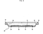
- the tray 30 includes a bottom plate 31 and an integral side wall 32 upwardly extended from a peripheral edge of the bottom plate 31 to have a substantially rectangular form.
- the side wall 32 is integrally provided at its upper end with a flange 33 extended outwardly by a certain length. Accordingly, the tray 30, on which food is placed, can be easily supported by any one pair of support rails 21, 22, and 23 among the upper, intermediate and lower support rails 21, 22 and 23 formed at the left and right walls 12 and 13, so as to cook the food in the cooking cavity 10.
- Figures 2 and 3 are side cross-sectional views showing a heater installed on an underside of the tray, which serves to cook food on the tray in cooperation with an upper heater fixedly installed on an upper portion of the cooking cavity, in which Figure 2 is a cross-sectional view taken along line II-II of Figure 1, and Figure 3 is a cross-sectional view taken along line III-III of Figure 1.
- Figure 4 is a cross-sectional view taken along line IV-IV of Figure 3.
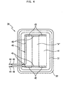
- the tray 30 includes a heater 40 shown in Figure 4, at its bottom plate 31, which is formed into a plate-shape to provide a heating surface.
- the heater 40 includes a thin conductive film 41 coated on its underside, first and second electrodes 42 and 43 disposed at both sides of the conductive film 41 to face each other, as shown in Figure 4, and a pair of terminals 44 shown in Figures 3 and 4, connected to the first and second electrodes 42 and 43 to allow electric power to be supplied to the heater 40.
- the conductive film 41 is produced from material, which allows electric current to flow between the first and second electrodes 42 and 43 through the shortest path, to generate heat by itself, and radiate the heat. Accordingly, the overall bottom plate 31 of the tray 30 on which the conductive film 41 is coated serves as a heating surface.
- the first electrodes 42 and the second electrodes 43 are electrically connected to the terminals 44. Consequently, when the terminals 44 are inserted in any one of the sockets 24, 25 and 26 of the cooking cavity 10 allowing external electric power to be supplied to the heater 40, the electric current flows between the first and second electrodes 42 and 43 through the conductive film 41. This causes the conductive film 41 to generate heat.
- each of the first and second electrodes 42 and 43 is divided into two electrodes to be spaced from each other by a certain distance.
- the center area "A" of the conductive film 41 is heated by heat transmitted from its surrounding areas, thereby allowing the conductive film 41 to be evenly heated to a high temperature.
- the center area "A" of the conductive film 41 may be evenly heated without the division of each of the first and second electrodes 42 and 43.
- each of the first and second electrodes 42 and 43 is bent outward to have an arched shape (not shown).
- a distance between the first and second electrodes 42 and 43 is increased at the center potion of the electrodes, compared to the structure at end portions of the electrodes. Accordingly, flow of electric current is relatively weakened at the center area "A" of the conductive film 41, thereby causing the conductive film 41 to be evenly heated.
- the terminals 44 are positioned on the underside of the tray 30 such that inner ends of the terminals 44 are connected to the first and second electrodes 42 and 43 and outer ends of the terminals 44 are projected from the tray 30. Therefore, when the outer ends of the terminals 44 are inserted into any one of the sockets 24, 25 and 26 installed on the rear wall 11 of the cooking cavity 10, the first and second electrodes 42 and 43 are supplied with electric power.
- the terminals 44 are surrounded with insulating sheaths 46 to prevent electricity leakage.
- the tray 30 includes a cover plate 50 at its lower surface covering the heater 40 so as to protect the heater 40 from external impact.
- the cover plate 50 is attached to the lower surface of the tray 30 by sealing material 34 such as silicon. Accordingly, by attaching the cover plate 50 to the tray 30, the conductive film 41 and the first and second electrodes 42 and 43 can be protected from infiltration of moisture and from breakage by external impact.
- the heater 40 according to the present invention is comprised of the conductive film 41, the first and second electrodes 42 and 43, and the terminals 44, the heater 40 can be remarkably decreased in its thickness and weight, thereby preventing considerable increase of overall thickness and weight of the tray 30. Furthermore, since the heater 40 is directly attached to the tray 30 so as to permit the tray 30 to generate heat by itself to cook food placed thereon, heating efficiency is considerably improved and power consumption is reduced.
- the tray 30 having the heater 40 installed thereon is made of metallic material having excellent heat transfer properties, such as aluminum and stainless steel.
- metallic material having excellent heat transfer properties, such as aluminum and stainless steel.
- Figure 5 is a fragmentary perspective view showing a part of the tray 30 in which the terminals 44 are installed to allow external power to be supplied to the heater.
- Figure 6 is a cross-sectional view showing the terminals 44 inserted in the socket.
- Figure 7 is a cross-sectional view taken along line VII-VII of Figure 6.
- the tray 30 is provided at its lower surface with a pair of semi-circular grooves 35.
- the cover plate 50 is provided with a pair of semi-circular grooves 51 at its portion corresponding to the semi-circular grooves 35 of the tray 30. Therefore, two holes defined between the semi-circular grooves 35 of the tray 30 and the semi-circular grooves 51 of the cover plate 50 receive the insulating sheaths 46 attached to outer surfaces of the terminals 44.
- Inner ends of the terminals 44 are attached to a lower surface of the bottom plate 31 of the tray 30 by spot welding, so as to connect the terminals 44 to the first and second electrodes 42 and 43.
- Outer ends of the terminals 44 are extended from the tray 30 together with a part of the insulating sheaths 46 surrounding the terminals 44, to enable the terminals 44 to be inserted into any one of the sockets 24, 25 and 26.
- Sealing material is applied to a gap between the terminals 44 and the semi-circular grooves 35 and 51 so as to prevent water or foreign substances from infiltrating into the heater 40 through the gap.
- the socket 24 includes a guide cover 28 protruded from the rear wall 11 of the cooking cavity 10 to guide insertion of the terminals 44 of the heater 40 (sockets 25 and 26 are similarly constructed but not shown). Socket terminals 29 are provided in the guide cover 28 and connected to the inserted terminals 44 of the heater 40 to allow external power to be supplied to the heater 40.
- Each of the sockets 24, 25 and 26 is provided in the guide cover 28 with a micro switch 60, which is turned on and off when the terminals 44 of the heater 40 are inserted into and separated from the one socket. Accordingly, the cooking apparatus 100 can register which of the support rails 21, 22 and 23 the tray 30 is placed on, and can thus control current supplied to the heater 40.
- the tray 30 is placed on the upper support rails 21, and the terminals 44 of the heater 40 are inserted into the upper socket 24, for the purpose of cooking of a small sized food, the tray 30 is positioned at a level closest to the upper heater 4 installed on the top wall of the cooking cavity 10. Consequently, even if the heater 40 of the tray 30 is applied with relatively little electric power, the food placed on the tray 30 can be quickly cooked.
- the tray 30 is placed on the intermediate support rails 22, and the terminals 44 of the heater 40 are inserted into the intermediate socket 25, for the purpose of cooking of a moderate sized food, the tray 30 is positioned at a level moderately remote from the upper heater 4. Consequently, the heater 40 of the tray 30 is applied with moderate electric power to cook the food placed on the tray 30.
- the tray 30 is placed on the lower support rails 23, and the terminals 44 of the heater 40 are inserted into the lower socket 26, for the purpose of cooking of a large sized food, the tray 30 is positioned at a level farthest from the upper heater 4. In this case, the heater 40 of the tray 30 is applied with high electric power to cook the large sized food placed on the tray 30.
- the cooking apparatus 100 is provided with a manual cooking temperature adjustment system. This would allow the user to cook foods with varying sizes at varying temperature. For instance, a food, such as a steak requiring little space and high cooking temperatures could be cooked on the upper support rails.
- the cooking apparatus 100 since the cooking apparatus 100 according to the present invention is designed to cook food by heat evenly generated through the bottom plate 31 of the tray 30 from the heater 40 attached to the bottom plate 31, the tray 30 may be used as a steaming container to steam food.
- the tray 30 includes a stepped portion 36 formed at an inner surface of the side wall 32, and a grill plate 70 to be placed on an upper side of the tray 30.
- the tray 30 is first filled with water up to the stepped portion 36 serving as a water level mark, and the grill plate 70 is placed on the upper side of the tray 30 with food placed on the grill 70.
- the tray 30 is placed on one pair of support rails, which is selected among the support rails 21, 22 and 23 according to a size of the food, and then pushed into the cooking cavity 10. As the tray 30 is pushed into the cooking cavity 10, the terminals 40 of the heater 40 attached to the tray 30 are inserted into the socket corresponding to the selected support rails, thereby allowing electric power to be supplied to the heater 40.
- the heater 40 activates and causes the conductive film 41 to generate heat, and thus the bottom plate 31 of the tray 30 is evenly heated. Accordingly, the water contained in the tray 30 is vaporized by the heated bottom plate 31, thereby steaming the food placed on the grill plate 70.
- the cooking apparatus 100 since the cooking apparatus 100 according to the present invention is constructed so the tray 30 is provided at its lower surface with the thin and light heater 40, and the heater 40 is selectively supplied with electric power from one of the sockets 24, 25 and 26, the cooking apparatus 100 may be used alone or in conjunction with another heating source such as a magnetron generating microwaves, depending on a kind and a size of food and a cooking manner.
- another heating source such as a magnetron generating microwaves
- the present invention provides a cooking apparatus 100, which includes a tray having a heater to cook food placed on the tray in a direct heating manner. Accordingly, heating efficiency of the cooking apparatus 100 is considerably improved, and thus electric power consumption is dramatically reduced, compared to a conventional cooking apparatus.
- a tray of the cooking apparatus 100 according to the present invention is provided at its lower surface with a thin heater attached thereto, thereby dispensing with a necessity for providing an additional heater in a cooking cavity of the cooking apparatus 100, an effective cooking space in the cooking cavity is increased, and manufacturing cost and time is reduced. Additionally, it is not necessary to operate a cooling fan for cooling a lower space of the cooking cavity at high speed and for a long period of time.
- a tray of the cooking apparatus 100 according to the present invention is evenly heated throughout its area to directly heat food placed on the tray, a lower part of the food is quickly and evenly cooked, and a procedure of turning food over during a grilling operation is not necessary.
- a tray of the cooking apparatus 100 according to the present invention is directly heated at its bottom plate, a steaming operation can be easily performed where the tray contains water therein.
Landscapes
- Engineering & Computer Science (AREA)
- Chemical & Material Sciences (AREA)
- Combustion & Propulsion (AREA)
- Mechanical Engineering (AREA)
- General Engineering & Computer Science (AREA)
- Food Science & Technology (AREA)
- Baking, Grill, Roasting (AREA)
- Electric Stoves And Ranges (AREA)
- Surface Heating Bodies (AREA)
Claims (30)
- Appareil de cuisson comprenant:- une cavité de cuisson (10);- au moins une paire de rails de support (21, 22, 23) compris respectivement sur les deux parois latérales (12, 13) de la cavité de cuisson (10);- un plateau (30) sur lequel les aliments sont placés;- un dispositif de chauffage (40) pour chauffer directement le plateau (30) pour cuisiner les aliments par activation du dispositif de chauffage (40), présentant une paire de bornés (44); et- au moins une prise femelle (24, 25, 26) comprise sur une paroi latérale (11) de la cavité de cuisson (10) permettant d'alimenter électriquement le dispositif de chauffage (40) lorsqu'elle est connectée aux bornes (44);caractérisé en ce que:- le dispositif de chauffage (40) comprend:- une couche conductrice (41) revêtant une surface inférieure du plateau (30); et- des première et seconde électrodes opposées l'une de l'autre (42, 43) connectées à la couche conductrice (41), la couche conductrice (41) chauffant sous l'effet d'un courant électrique circulant à travers la couche conductrice (41) entre les première et seconde électrodes (42, 43).
- Appareil de cuisson selon la revendication 1, dans lequel chacune des première et seconde électrodes (42, 43) est divisée dans la partie centrale de celle-ci, les segments d'électrodes séparés étant espacés l'un de l'autre d'une distance, avec un fil conducteur connecté entre eux, pour éviter que la zone centrale de la couche conductrice (41) ne soit chauffée davantage que la zone périphérique de celle-ci.
- Appareil de cuisson selon la revendication 1 ou 2, dans lequel chacune des première et seconde électrodes présente une forme arquée, pour éviter que la zone centrale de la couche conductrice (41) ne soit chauffée davantage que la zone périphérique de celle-ci.
- Appareil de cuisson selon l'une quelconque des revendications précédentes, dans lequel:- la paire de bornes (44) est positionnée sur un côté du plateau (30) de telle sorte que les extrémités internes des bornes (44) sont connectées aux première et seconde électrodes, et que les extrémités externes des bornes (44) font saillie vers l'extérieur depuis le plateau (30); et- lorsque le plateau (30) est poussé dans la cavité de cuisson (10) le long des rails de support (21, 22, 23), la paire de bornes (44) est insérée dans la prise femelle (24, 25, 26) correspondant aux rails de support (21, 22, 23), pour permettre au plateau (30) d'être chauffé par un courant électrique circulant à travers la couche conductrice (41) entre les première et seconde électrodes.
- Appareil de cuisson selon la revendication 4, dans lequel:- chacune de la paire de bornes (44), à l'exception de son extrémité externe, est entourée d'une gaine isolante (46); et- les surfaces inférieures du plateau (30) et la plaque de couverture (50) comprennent une paire de rainures (35, 51), respectivement, pour définir une paire de trous, dans lesquels la paire de bornes (44) est reçue.
- Appareil de cuisson selon la revendication 5, dans lequel un matériau isolant est appliqué sur les rainures du plateau (30) et de la plaque de couverture (50) pour éviter l'infiltration d'humidité dans le dispositif de chauffage (40).
- Appareil de cuisson selon l'une quelconque des revendications 1 à 6, dans lequel la surface inférieure du plateau (30) est couverte d'une plaque de couverture (50) de façon à éviter que le dispositif de chauffage (40) fixé au plateau (30) ne soit à découvert.
- Appareil de cuisson selon l'une quelconque des revendications 1 à 7, dans lequel:- la au moins une paire de rails de support (21, 22, 23) comprend une pluralité de paires de rails de support (21, 22, 23), qui sont positionnés sur les deux parois latérales (12, 13) de la cavité de cuisson (10) pour être espacés verticalement l'un de l'autre d'une distance; et- la au moins une prise femelle (24, 25, 26) comprend une pluralité de prises femelles (24, 25, 26), qui sont positionnées sur la paroi arrière (11) de la cavité de cuisson (10) pour correspondre aux positions de la pluralité de paires de rails de support (21, 22, 23).
- Appareil de cuisson selon la revendication 8, comprenant en outre un dispositif de chauffage supérieur (4) fixé sur une partie supérieure de la paroi arrière (11) de la cavité de cuisson (10) pour cuire des aliments en conjonction avec le dispositif de chauffage (40) monté au niveau du plateau (30).
- Dispositif de chauffage selon la revendication 8 ou 9, dans lequel chacune de la pluralité de prises femelles (24, 25, 26) comprend un micro-interrupteur (60) qui est activé et désactivé lorsque les bornes (44) sont insérées dans, et extraites de, une prise correspondante parmi les prises femelles (24, 25, 26), de façon à contrôler le courant électrique alimentant le dispositif de chauffage (40), en enregistrant dans quelle prise femelle (24, 25, 26) le dispositif de chauffage (40) est inséré.
- Appareil de cuisson selon l'une quelconque des revendications précédentes, dans lequel le plateau (30) comprend une plaque de fond (31) et une paroi latérale (32) s'étendant vers le haut depuis un bord périphérique de la plaque de fond (31), et le dispositif de chauffage (40) est positionné sur une surface inférieure de la plaque de fond (31).
- Appareil de cuisson selon la revendication 11, comprenant en outre une plaque de gril (70) placée sur une extrémité supérieure du plateau (30), dans lequel la paroi latérale (32) du plateau (30) comprend une partie surélevée (36) à une hauteur prédéterminée d'une surface intérieure de celle-ci, sur laquelle, lorsque le dispositif de chauffage (40) est activé et que le plateau (30) est empli d'eau, la vapeur cuit les aliments.
- Appareil de cuisson selon la revendication 1, dans lequel:- la cavité de cuisson (10) est sensiblement rectangulaire;- le dispositif de chauffage (40) est un élément chauffant (40);- l'appareil de cuisson inclut un système de chauffage comprenant la au moins une prise femelle (24, 25, 26) à un certain emplacement à l'intérieur de la cavité de cuisson (10) correspondant à une position souhaitée de cuisson, la prise femelle (24, 25, 26) pouvant coopérer avec la paire de bornes (44) pour alimenter l'élément chauffant (40);- l'appareil de cuisson incluant un système de support (21, 22, 23) comprenant la paire de rails de supports (21, 22, 23) qui supporte l'élément chauffant (40) à un emplacement correspondant à la position de la prise femelle (24, 25, 26);- la couche conductrice (41) étant disposée pour revêtir une surface inférieure de l'élément chauffant (40) de telle sorte que l'élément chauffant (40) est fixé directement sur le plateau (30) pour permettre au plateau (30) de générer de la chaleur en lui-même pour cuire les aliments placés sur celui-ci.
- Appareil de cuisson selon la revendication 13, dans lequel l'élément chauffant (40) comprend les première et seconde électrodes (42, 43) connectées à la couche conductrice (41).
- Appareil de cuisson selon la revendication 13 ou 14, dans lequel les première et seconde électrodes (42, 43) sont opposées l'une à l'autre.
- Appareil de cuisson selon la revendication 14 ou 15, dans lequel le courant électrique circulant à travers la couche conductrice (41) entre les première et seconde électrodes (42, 43) chauffe la couche conductrice (41).
- Appareil de cuisson selon la revendication 14, 15 ou 16, dans lequel chacune des première et seconde électrodes (42, 43) est divisée dans sa partie centrale.
- Appareil de cuisson selon la revendication 17, dans lequel les segments d'électrodes séparés sont espacés l'un de l'autre et comprennent un fil conducteur connecté entre eux.
- Appareil de cuisson selon l'une quelconque des revendications 14 à 18, dans lequel chacune des première et seconde électrodes (42, 43) est recourbée vers l'extérieur pour présenter une forme arquée.
- Appareil de cuisson selon l'une quelconque des revendications 14 à 19, dans lequel les extrémités internes des bornes (44) sont connectées aux première et seconde électrodes (42, 43), respectivement, et les extrémités externes des bornes (44) font saillie vers l'extérieur.
- Appareil de cuisson selon la revendication 20, dans lequel, lorsque l'élément chauffant (40) est supporté par le système de support (21, 22, 23), les bornes (44) coopèrent avec la prise femelle (24, 25, 26) pour alimenter la couche conductrice (41).
- Appareil de cuisson selon la revendication 21, dans lequel les bornes (44), à l'exception de l'extrémité externe des bornes (44), sont entourées de gaines isolantes (46).
- Appareil de cuisson selon la revendication 22, comprenant en outre:- une paire de rainures semi-circulaires à des emplacements de la surface inférieure de l'élément chauffant (40); et- une plaque de couverture (50) couvrant une surface inférieure de l'élément chauffant (40), la plaque de couverture (50) comprenant une paire de rainures semi-circulaires à des emplacements correspondant aux positions des rainures dans la surface inférieure de l'élément chauffant (40), les rainures dans la surface inférieure de l'élément chauffant (40) et les rainures dans la plaque de couverture (50) recevant les gaines isolantes (46).
- Appareil de cuisson selon la revendication 23, comprenant en outre un matériau isolant appliqué sur les rainures de l'élément chauffant (40) et les rainures dans la plaque de couverture (50) pour éviter l'infiltration d'humidité dans le dispositif de chauffage (40).
- Appareil de cuisson selon l'une quelconque des revendications 13 à 24, dans lequel le système de support (21, 22, 23) comprend une pluralité de rails de support (21, 22, 23) espacés verticalement l'un de l'autre d'une distance.
- Appareil de cuisson selon la revendication 25, dans lequel la prise femelle (24, 25, 26) est multiple et les positions des prises femelles (24, 25, 26) correspondent aux positions verticales des rails de support (21, 22, 23).
- Appareil de cuisson selon la revendication 26, comprenant en outre un dispositif de chauffage supérieur (4) fixé sur une partie supérieure de la paroi arrière (11) de l'espace de cuisson rectangulaire.
- Appareil de cuisson selon la revendication 26 ou 27, dans lequel les prises femelles (24, 25, 26) comprennent des micro-interrupteurs qui sont activés lorsque les prises femelles (24, 25, 26) coopèrent avec les bornes (44), et désactivés lorsque les prises femelles (24, 25, 26) ne coopèrent pas avec les bornes (44).
- Appareil de cuisson selon l'une quelconque des revendications 13 à 28, dans lequel l'élément chauffant (40) comprend:- une plaque de fond (31) et une paroi latérale (32) s'étendant vers le haut depuis un bord périphérique de la plaque de fond (31), et une couche conductrice (41) sur une surface inférieure de la plaque de fond (31).
- Appareil de cuisson selon la revendication 29, dans lequel l'élément chauffant (40) comprend une plaque de gril (70) sur une extrémité supérieure de l'élément chauffant (40), dans lequel la paroi latérale (32) du plateau (30) comprend une partie surélevée (36) à une hauteur prédéterminée de sa surface intérieure, sur laquelle, lorsque le dispositif de chauffage (40) est activé et que des aliments sont placés sur la plaque de grille (70), la vapeur générée depuis l'eau contenue dans le plateau (30) cuit les aliments.
Applications Claiming Priority (2)
| Application Number | Priority Date | Filing Date | Title |
|---|---|---|---|
| KR2003017753 | 2003-03-21 | ||
| KR10-2003-0017753A KR100526206B1 (ko) | 2003-03-21 | 2003-03-21 | 조리장치 |
Publications (2)
| Publication Number | Publication Date |
|---|---|
| EP1460342A1 EP1460342A1 (fr) | 2004-09-22 |
| EP1460342B1 true EP1460342B1 (fr) | 2006-05-31 |
Family
ID=36590826
Family Applications (1)
| Application Number | Title | Priority Date | Filing Date |
|---|---|---|---|
| EP03257336A Expired - Lifetime EP1460342B1 (fr) | 2003-03-21 | 2003-11-20 | Appareil de cuisson |
Country Status (6)
| Country | Link |
|---|---|
| US (1) | US6891133B2 (fr) |
| EP (1) | EP1460342B1 (fr) |
| JP (1) | JP3863138B2 (fr) |
| KR (1) | KR100526206B1 (fr) |
| CN (1) | CN1242212C (fr) |
| DE (1) | DE60305636T2 (fr) |
Cited By (7)
| Publication number | Priority date | Publication date | Assignee | Title |
|---|---|---|---|---|
| US10451290B2 (en) | 2017-03-07 | 2019-10-22 | Whirlpool Corporation | Forced convection steam assembly |
| US10619862B2 (en) | 2018-06-28 | 2020-04-14 | Whirlpool Corporation | Frontal cooling towers for a ventilation system of a cooking appliance |
| US10627116B2 (en) | 2018-06-26 | 2020-04-21 | Whirlpool Corporation | Ventilation system for cooking appliance |
| US10660162B2 (en) | 2017-03-16 | 2020-05-19 | Whirlpool Corporation | Power delivery system for an induction cooktop with multi-output inverters |
| US10837652B2 (en) | 2018-07-18 | 2020-11-17 | Whirlpool Corporation | Appliance secondary door |
| US10837651B2 (en) | 2015-09-24 | 2020-11-17 | Whirlpool Corporation | Oven cavity connector for operating power accessory trays for cooking appliance |
| US11777190B2 (en) | 2015-12-29 | 2023-10-03 | Whirlpool Corporation | Appliance including an antenna using a portion of appliance as a ground plane |
Families Citing this family (50)
| Publication number | Priority date | Publication date | Assignee | Title |
|---|---|---|---|---|
| DE10258727A1 (de) * | 2002-12-05 | 2004-06-24 | Schott Glas | Ofen |
| EP1607684A1 (fr) * | 2003-03-13 | 2005-12-21 | Matsushita Electric Industrial Co., Ltd. | Dispositif de chauffage haute frequence equipe d'une fonction de generation de vapeur |
| JP4314911B2 (ja) * | 2003-08-20 | 2009-08-19 | スタンレー電気株式会社 | 車両前照灯 |
| DE102004050125A1 (de) * | 2004-10-14 | 2006-04-20 | BSH Bosch und Siemens Hausgeräte GmbH | Gargeräteheizvorrichtung |
| CA2589319C (fr) * | 2004-12-03 | 2014-05-13 | Turbochef Technologies, Inc. | Four a convection grande vitesse |
| US20080190300A1 (en) * | 2005-05-09 | 2008-08-14 | Adamski Joseph R | Radiant Oven Having Octagonal Cell and/or Sliding Heating Elements |
| JP4589825B2 (ja) | 2005-06-23 | 2010-12-01 | 株式会社東芝 | 加熱調理装置 |
| US7417204B2 (en) * | 2006-03-15 | 2008-08-26 | Lg Electronics Inc. | Cooking apparatus and method for controlling the same |
| US7420997B2 (en) | 2006-10-16 | 2008-09-02 | Corning Incorporated | Wavelength control in wavelength selective, phase, and gain regions of semiconductor lasers |
| JP4957201B2 (ja) * | 2006-11-17 | 2012-06-20 | パナソニック株式会社 | 加熱調理器 |
| EP2168403B1 (fr) * | 2007-06-05 | 2021-02-17 | ResMed Pty Ltd | Radiateur électrique à application spécifique pour humidification et réchauffage de fumées |
| TR201005128T1 (tr) * | 2007-12-31 | 2011-02-21 | Arçeli̇k Anoni̇m Şi̇rketi̇ | Bir fırın. |
| KR101544551B1 (ko) * | 2009-05-04 | 2015-08-13 | 엘지전자 주식회사 | 조리기기 |
| DE102009054586A1 (de) * | 2009-12-14 | 2011-06-16 | BSH Bosch und Siemens Hausgeräte GmbH | Garraumteiler für ein Gargerät sowie Gargerät mit einem derartigen Garraumteiler |
| CN102119836A (zh) * | 2010-01-11 | 2011-07-13 | 谢水旺 | 电热管采用活动安装方式的电烤箱 |
| CN102192543A (zh) * | 2010-03-19 | 2011-09-21 | 乐金电子(天津)电器有限公司 | 多功能微波炉 |
| DE102010040959A1 (de) * | 2010-09-17 | 2012-03-22 | BSH Bosch und Siemens Hausgeräte GmbH | Beheizbarer Einschub-Garraumteiler und Gargerät |
| US20120085745A1 (en) * | 2010-10-08 | 2012-04-12 | Cambro Manufacturing Company | Dual Climate Cart and Tray for Accommodating Comestible Items and a Method of Operating the Same |
| DE102010062505A1 (de) * | 2010-12-07 | 2012-06-14 | BSH Bosch und Siemens Hausgeräte GmbH | Verfahren zum Behandeln einer Speise unter Dampf, Einschub-Gargutträger und Gargeräte zum Betrieb eines Einschub-Gargutträgers |
| DE102010062500A1 (de) * | 2010-12-07 | 2012-06-14 | BSH Bosch und Siemens Hausgeräte GmbH | Beheizbarer Garraumeinsatz und Gargerät mit mindestens einer Mikrowellenquelle |
| DE102010062503A1 (de) * | 2010-12-07 | 2012-06-14 | BSH Bosch und Siemens Hausgeräte GmbH | Gargutträger |
| DE102010063464A1 (de) | 2010-12-17 | 2012-06-21 | BSH Bosch und Siemens Hausgeräte GmbH | Anschlusselement, Haushaltsgerät mit solchem Anschlusselement und Einsetzmodul |
| EP2520169B1 (fr) * | 2011-04-29 | 2019-12-04 | Electrolux Home Products Corporation N.V. | Porte de four de cuisson et four de cuisson |
| EP3708213B1 (fr) | 2012-03-15 | 2022-11-02 | ResMed Pty Ltd | Appareil de chauffage |
| CN104856578A (zh) * | 2014-02-24 | 2015-08-26 | 吴建明 | 方便更换电热板的烤炉加热装置 |
| WO2016018820A1 (fr) * | 2014-07-28 | 2016-02-04 | Patentco LLC | Four posable avec éléments de conduction avancés |
| KR101565713B1 (ko) * | 2014-11-14 | 2015-11-03 | 김현동 | 온돌형 청국장 발효기 |
| USD787041S1 (en) | 2015-09-17 | 2017-05-16 | Whirlpool Corporation | Gas burner |
| TWI563918B (zh) * | 2015-10-23 | 2017-01-01 | Ovens that produce steam | |
| CN108078409A (zh) * | 2015-10-29 | 2018-05-29 | 泉州东行贸易有限公司 | 一种门体 |
| US10145568B2 (en) | 2016-06-27 | 2018-12-04 | Whirlpool Corporation | High efficiency high power inner flame burner |
| EP3287700A1 (fr) * | 2016-08-23 | 2018-02-28 | Electrolux Appliances Aktiebolag | Plateau de four et four pour fumer ou applications de traitement de vapeur aromatique |
| US10488055B2 (en) | 2016-12-30 | 2019-11-26 | Whirlpool Corporation | Cavity connector |
| EP3566006A4 (fr) * | 2017-01-06 | 2020-11-11 | Revolution Cooking, LLC | Système de fonctionnement pour un appareil de cuisson |
| US10551056B2 (en) | 2017-02-23 | 2020-02-04 | Whirlpool Corporation | Burner base |
| WO2019038003A1 (fr) * | 2017-08-23 | 2019-02-28 | BSH Hausgeräte GmbH | Appareil de cuisson doté d'une fixation spécifique d'un rail de réception pour un support de nourriture à cuire |
| KR102355669B1 (ko) * | 2017-09-29 | 2022-01-25 | 엘지전자 주식회사 | 피가열 물체 지지대 |
| CN107713727B (zh) * | 2017-11-02 | 2021-06-18 | 广东美的厨房电器制造有限公司 | 烤盘组件和具有其的烹饪器具 |
| US10955142B2 (en) * | 2018-07-03 | 2021-03-23 | Electrolux Home Products, Inc. | Cooking oven with steam generator inside cooking cavity |
| CN110089952A (zh) * | 2019-05-14 | 2019-08-06 | 苏州博学智能科技有限公司 | 一种自动出炉的智能电烤箱 |
| CN110236401B (zh) * | 2019-06-03 | 2024-02-27 | 华帝股份有限公司 | 一种防碰撞结构及应用其的烹饪设备 |
| CN111012210A (zh) * | 2019-12-31 | 2020-04-17 | 广东美的厨房电器制造有限公司 | 烹饪装置及烹饪装置的加热方法 |
| US20220065459A1 (en) | 2020-02-28 | 2022-03-03 | Team International Group of America Inc. | Cooking appliance |
| US11175048B2 (en) | 2020-02-28 | 2021-11-16 | Team International Group of America Inc. | Cooking appliance |
| WO2021178845A1 (fr) * | 2020-03-06 | 2021-09-10 | Spectrum Brands, Inc. | Appareil de cuisson à capacités de chauffage conductrices |
| CN112021949B (zh) * | 2020-09-09 | 2024-05-14 | 上海庖钵智能科技有限公司 | 一种智能烹饪系统及烹饪方法 |
| EP4001773A1 (fr) * | 2020-11-20 | 2022-05-25 | BSH Hausgeräte GmbH | Insert de chambre de cuisson pourvu d'élément chauffant intégré et unité de distribution d'énergie remplaçable, agencement, appareil de cuisson et procédé |
| CN115530635A (zh) * | 2021-06-30 | 2022-12-30 | 广东美的厨房电器制造有限公司 | 烹饪器具 |
| WO2023237209A1 (fr) * | 2022-06-10 | 2023-12-14 | V-Zug Ag | Plateau de cuisson destiné à être utilisé dans un dispositif de cuisson et dispositif de cuisson comprenant un tel plateau de cuisson |
| CN117158795A (zh) * | 2023-09-20 | 2023-12-05 | 广东美的厨房电器制造有限公司 | 烹饪器具 |
Family Cites Families (10)
| Publication number | Priority date | Publication date | Assignee | Title |
|---|---|---|---|---|
| US2683795A (en) * | 1952-06-13 | 1954-07-13 | Tappan Stove Co | Portable electric cooking oven |
| US2976386A (en) * | 1958-03-31 | 1961-03-21 | Lewis L Salton | Electric food warmers |
| SE331525B (fr) * | 1968-12-03 | 1971-01-04 | Ankarsrums Bruk Ab | |
| US4517446A (en) * | 1981-10-13 | 1985-05-14 | Safeway Products Inc. | Heating shelf |
| US4459470A (en) * | 1982-01-26 | 1984-07-10 | The United States Of America As Represented By The Administrator Of The National Aeronautics And Space Administration | Glass heating panels and method for preparing the same from architectural reflective glass |
| FR2581165A1 (fr) * | 1985-04-26 | 1986-10-31 | Europ Equip Menager | Four electrique a usage domestique |
| DE3722617C1 (de) * | 1987-07-09 | 1988-10-06 | Bauknecht Hausgeraete | Elektrisch beheizbare Backauflage |
| DE4329962A1 (de) * | 1993-09-04 | 1995-03-09 | Licentia Gmbh | Elektrischer Back- und Bratofen |
| JPH10300098A (ja) | 1997-04-24 | 1998-11-13 | Toshiba Corp | ヒータ付き電子レンジ |
| US6362458B1 (en) * | 2001-01-30 | 2002-03-26 | Maytag Corporation | Food grilling system for oven cavity with byproduct removal |
-
2003
- 2003-03-21 KR KR10-2003-0017753A patent/KR100526206B1/ko not_active Expired - Fee Related
- 2003-09-25 US US10/669,504 patent/US6891133B2/en not_active Expired - Fee Related
- 2003-11-05 JP JP2003376168A patent/JP3863138B2/ja not_active Expired - Fee Related
- 2003-11-20 DE DE60305636T patent/DE60305636T2/de not_active Expired - Lifetime
- 2003-11-20 EP EP03257336A patent/EP1460342B1/fr not_active Expired - Lifetime
- 2003-11-28 CN CNB2003101188039A patent/CN1242212C/zh not_active Expired - Fee Related
Cited By (12)
| Publication number | Priority date | Publication date | Assignee | Title |
|---|---|---|---|---|
| US10837651B2 (en) | 2015-09-24 | 2020-11-17 | Whirlpool Corporation | Oven cavity connector for operating power accessory trays for cooking appliance |
| US11460195B2 (en) | 2015-09-24 | 2022-10-04 | Whirlpool Corporation | Oven cavity connector for operating power accessory trays for cooking appliance |
| US11777190B2 (en) | 2015-12-29 | 2023-10-03 | Whirlpool Corporation | Appliance including an antenna using a portion of appliance as a ground plane |
| US10451290B2 (en) | 2017-03-07 | 2019-10-22 | Whirlpool Corporation | Forced convection steam assembly |
| US10660162B2 (en) | 2017-03-16 | 2020-05-19 | Whirlpool Corporation | Power delivery system for an induction cooktop with multi-output inverters |
| US10627116B2 (en) | 2018-06-26 | 2020-04-21 | Whirlpool Corporation | Ventilation system for cooking appliance |
| US11226106B2 (en) | 2018-06-26 | 2022-01-18 | Whirlpool Corporation | Ventilation system for cooking appliance |
| US12140315B2 (en) | 2018-06-26 | 2024-11-12 | Whirlpool Corporation | Ventilation system for cooking appliance |
| US12560335B2 (en) | 2018-06-26 | 2026-02-24 | Whirlpool Corporation | Ventilation system for cooking appliance |
| US10619862B2 (en) | 2018-06-28 | 2020-04-14 | Whirlpool Corporation | Frontal cooling towers for a ventilation system of a cooking appliance |
| US11137145B2 (en) | 2018-06-28 | 2021-10-05 | Whirlpool Corporation | Frontal cooling towers for a ventilation system of a cooking appliance |
| US10837652B2 (en) | 2018-07-18 | 2020-11-17 | Whirlpool Corporation | Appliance secondary door |
Also Published As
| Publication number | Publication date |
|---|---|
| CN1242212C (zh) | 2006-02-15 |
| JP3863138B2 (ja) | 2006-12-27 |
| DE60305636T2 (de) | 2007-05-24 |
| CN1532458A (zh) | 2004-09-29 |
| DE60305636D1 (de) | 2006-07-06 |
| US6891133B2 (en) | 2005-05-10 |
| KR100526206B1 (ko) | 2005-11-08 |
| KR20040083184A (ko) | 2004-10-01 |
| US20040182849A1 (en) | 2004-09-23 |
| EP1460342A1 (fr) | 2004-09-22 |
| JP2004286429A (ja) | 2004-10-14 |
Similar Documents
| Publication | Publication Date | Title |
|---|---|---|
| EP1460342B1 (fr) | Appareil de cuisson | |
| EP2028424B1 (fr) | Procédé de préchauffage du four électrique | |
| EP1628079B1 (fr) | Cuiseur à vapeur surchauffée | |
| EP0023827B1 (fr) | Appareil de cuisson du type à circulation d'air chaud | |
| CA2051861C (fr) | Appareil de cuisson domestique | |
| US6191391B1 (en) | Warmer drawer for a cooking range | |
| KR20100119128A (ko) | 공기 순환 수단을 포함한 오븐 레인지 | |
| EP2789923B1 (fr) | Four électroménager avec évaporateur d'eau intégré | |
| EP2135009B1 (fr) | Four | |
| US6323472B1 (en) | Radiant electric heater for a microwave oven | |
| EP1628078B1 (fr) | Cuiseur à vapeur surchauffée | |
| US7019265B2 (en) | Turntable incorporating heating means and oven incorporating the same | |
| CA1201487A (fr) | Four a micro-ondes avec tableau de commandes en pente vers l'avant | |
| KR100794597B1 (ko) | 가열조리장치 | |
| GB2349457A (en) | Cooking appliance | |
| JP7756289B2 (ja) | 加熱調理器 | |
| JP2006317019A (ja) | 高周波加熱調理装置 | |
| AP470A (en) | Oven with electrical heating element. | |
| EP1972856B1 (fr) | Appareil de cuisine | |
| KR20080005014U (ko) | 조리장치 | |
| WO2002039020A2 (fr) | Four comportant une cavite equipee d'un plateau rotatif et d'un dispositif de chauffage | |
| JP2025167372A (ja) | 加熱調理器 | |
| JP2023028543A (ja) | 加熱調理器 | |
| GB2383125A (en) | An oven with microwave and resistance heating means. | |
| KR20100119141A (ko) | 열 차단 수단을 구비한 오븐 레인지 |
Legal Events
| Date | Code | Title | Description |
|---|---|---|---|
| PUAI | Public reference made under article 153(3) epc to a published international application that has entered the european phase |
Free format text: ORIGINAL CODE: 0009012 |
|
| 17P | Request for examination filed |
Effective date: 20031210 |
|
| AK | Designated contracting states |
Kind code of ref document: A1 Designated state(s): AT BE BG CH CY CZ DE DK EE ES FI FR GB GR HU IE IT LI LU MC NL PT RO SE SI SK TR |
|
| AX | Request for extension of the european patent |
Extension state: AL LT LV MK |
|
| 17Q | First examination report despatched |
Effective date: 20050131 |
|
| AKX | Designation fees paid |
Designated state(s): DE FR GB |
|
| GRAP | Despatch of communication of intention to grant a patent |
Free format text: ORIGINAL CODE: EPIDOSNIGR1 |
|
| GRAS | Grant fee paid |
Free format text: ORIGINAL CODE: EPIDOSNIGR3 |
|
| GRAA | (expected) grant |
Free format text: ORIGINAL CODE: 0009210 |
|
| AK | Designated contracting states |
Kind code of ref document: B1 Designated state(s): DE FR GB |
|
| REG | Reference to a national code |
Ref country code: GB Ref legal event code: FG4D |
|
| REF | Corresponds to: |
Ref document number: 60305636 Country of ref document: DE Date of ref document: 20060706 Kind code of ref document: P |
|
| ET | Fr: translation filed | ||
| PLBE | No opposition filed within time limit |
Free format text: ORIGINAL CODE: 0009261 |
|
| STAA | Information on the status of an ep patent application or granted ep patent |
Free format text: STATUS: NO OPPOSITION FILED WITHIN TIME LIMIT |
|
| 26N | No opposition filed |
Effective date: 20070301 |
|
| PGFP | Annual fee paid to national office [announced via postgrant information from national office to epo] |
Ref country code: GB Payment date: 20141021 Year of fee payment: 12 Ref country code: FR Payment date: 20141023 Year of fee payment: 12 Ref country code: DE Payment date: 20141021 Year of fee payment: 12 |
|
| REG | Reference to a national code |
Ref country code: DE Ref legal event code: R119 Ref document number: 60305636 Country of ref document: DE |
|
| GBPC | Gb: european patent ceased through non-payment of renewal fee |
Effective date: 20151120 |
|
| REG | Reference to a national code |
Ref country code: FR Ref legal event code: ST Effective date: 20160729 |
|
| PG25 | Lapsed in a contracting state [announced via postgrant information from national office to epo] |
Ref country code: GB Free format text: LAPSE BECAUSE OF NON-PAYMENT OF DUE FEES Effective date: 20151120 Ref country code: DE Free format text: LAPSE BECAUSE OF NON-PAYMENT OF DUE FEES Effective date: 20160601 |
|
| PG25 | Lapsed in a contracting state [announced via postgrant information from national office to epo] |
Ref country code: FR Free format text: LAPSE BECAUSE OF NON-PAYMENT OF DUE FEES Effective date: 20151130 |