EP1460364A2 - Wärmetauscher für ein Kraftfahrzeug - Google Patents
Wärmetauscher für ein Kraftfahrzeug Download PDFInfo
- Publication number
- EP1460364A2 EP1460364A2 EP04251603A EP04251603A EP1460364A2 EP 1460364 A2 EP1460364 A2 EP 1460364A2 EP 04251603 A EP04251603 A EP 04251603A EP 04251603 A EP04251603 A EP 04251603A EP 1460364 A2 EP1460364 A2 EP 1460364A2
- Authority
- EP
- European Patent Office
- Prior art keywords
- heat exchanger
- tube
- automotive
- header
- tube lengths
- Prior art date
- Legal status (The legal status is an assumption and is not a legal conclusion. Google has not performed a legal analysis and makes no representation as to the accuracy of the status listed.)
- Withdrawn
Links
- 239000012530 fluid Substances 0.000 claims abstract description 31
- 239000003507 refrigerant Substances 0.000 claims abstract description 21
- 238000000926 separation method Methods 0.000 claims abstract description 8
- 239000012212 insulator Substances 0.000 claims abstract description 5
- 238000012546 transfer Methods 0.000 claims description 7
- 238000004378 air conditioning Methods 0.000 claims description 2
- 238000004891 communication Methods 0.000 claims description 2
- 238000009413 insulation Methods 0.000 claims description 2
- 230000002401 inhibitory effect Effects 0.000 claims 1
- 239000007789 gas Substances 0.000 description 21
- 238000013461 design Methods 0.000 description 12
- 239000003570 air Substances 0.000 description 5
- 238000001816 cooling Methods 0.000 description 5
- 238000004806 packaging method and process Methods 0.000 description 4
- CBENFWSGALASAD-UHFFFAOYSA-N Ozone Chemical compound [O-][O+]=O CBENFWSGALASAD-UHFFFAOYSA-N 0.000 description 2
- 238000013459 approach Methods 0.000 description 2
- 230000000694 effects Effects 0.000 description 2
- 238000010438 heat treatment Methods 0.000 description 2
- VNWKTOKETHGBQD-UHFFFAOYSA-N methane Chemical compound C VNWKTOKETHGBQD-UHFFFAOYSA-N 0.000 description 2
- 230000002411 adverse Effects 0.000 description 1
- 239000012080 ambient air Substances 0.000 description 1
- 238000005219 brazing Methods 0.000 description 1
- 230000001143 conditioned effect Effects 0.000 description 1
- 230000000779 depleting effect Effects 0.000 description 1
- 230000007613 environmental effect Effects 0.000 description 1
- 239000003345 natural gas Substances 0.000 description 1
- 238000004088 simulation Methods 0.000 description 1
- 230000029305 taxis Effects 0.000 description 1
- 238000012360 testing method Methods 0.000 description 1
- 238000010792 warming Methods 0.000 description 1
Images


Classifications
-
- F—MECHANICAL ENGINEERING; LIGHTING; HEATING; WEAPONS; BLASTING
- F28—HEAT EXCHANGE IN GENERAL
- F28D—HEAT-EXCHANGE APPARATUS, NOT PROVIDED FOR IN ANOTHER SUBCLASS, IN WHICH THE HEAT-EXCHANGE MEDIA DO NOT COME INTO DIRECT CONTACT
- F28D1/00—Heat-exchange apparatus having stationary conduit assemblies for one heat-exchange medium only, the media being in contact with different sides of the conduit wall, in which the other heat-exchange medium is a large body of fluid, e.g. domestic or motor car radiators
- F28D1/02—Heat-exchange apparatus having stationary conduit assemblies for one heat-exchange medium only, the media being in contact with different sides of the conduit wall, in which the other heat-exchange medium is a large body of fluid, e.g. domestic or motor car radiators with heat-exchange conduits immersed in the body of fluid
- F28D1/04—Heat-exchange apparatus having stationary conduit assemblies for one heat-exchange medium only, the media being in contact with different sides of the conduit wall, in which the other heat-exchange medium is a large body of fluid, e.g. domestic or motor car radiators with heat-exchange conduits immersed in the body of fluid with tubular conduits
- F28D1/053—Heat-exchange apparatus having stationary conduit assemblies for one heat-exchange medium only, the media being in contact with different sides of the conduit wall, in which the other heat-exchange medium is a large body of fluid, e.g. domestic or motor car radiators with heat-exchange conduits immersed in the body of fluid with tubular conduits the conduits being straight
- F28D1/0535—Heat-exchange apparatus having stationary conduit assemblies for one heat-exchange medium only, the media being in contact with different sides of the conduit wall, in which the other heat-exchange medium is a large body of fluid, e.g. domestic or motor car radiators with heat-exchange conduits immersed in the body of fluid with tubular conduits the conduits being straight the conduits having a non-circular cross-section
- F28D1/05366—Assemblies of conduits connected to common headers, e.g. core type radiators
- F28D1/05375—Assemblies of conduits connected to common headers, e.g. core type radiators with particular pattern of flow, e.g. change of flow direction
-
- F—MECHANICAL ENGINEERING; LIGHTING; HEATING; WEAPONS; BLASTING
- F28—HEAT EXCHANGE IN GENERAL
- F28D—HEAT-EXCHANGE APPARATUS, NOT PROVIDED FOR IN ANOTHER SUBCLASS, IN WHICH THE HEAT-EXCHANGE MEDIA DO NOT COME INTO DIRECT CONTACT
- F28D1/00—Heat-exchange apparatus having stationary conduit assemblies for one heat-exchange medium only, the media being in contact with different sides of the conduit wall, in which the other heat-exchange medium is a large body of fluid, e.g. domestic or motor car radiators
- F28D1/02—Heat-exchange apparatus having stationary conduit assemblies for one heat-exchange medium only, the media being in contact with different sides of the conduit wall, in which the other heat-exchange medium is a large body of fluid, e.g. domestic or motor car radiators with heat-exchange conduits immersed in the body of fluid
- F28D1/04—Heat-exchange apparatus having stationary conduit assemblies for one heat-exchange medium only, the media being in contact with different sides of the conduit wall, in which the other heat-exchange medium is a large body of fluid, e.g. domestic or motor car radiators with heat-exchange conduits immersed in the body of fluid with tubular conduits
- F28D1/047—Heat-exchange apparatus having stationary conduit assemblies for one heat-exchange medium only, the media being in contact with different sides of the conduit wall, in which the other heat-exchange medium is a large body of fluid, e.g. domestic or motor car radiators with heat-exchange conduits immersed in the body of fluid with tubular conduits the conduits being bent, e.g. in a serpentine or zig-zag
- F28D1/0475—Heat-exchange apparatus having stationary conduit assemblies for one heat-exchange medium only, the media being in contact with different sides of the conduit wall, in which the other heat-exchange medium is a large body of fluid, e.g. domestic or motor car radiators with heat-exchange conduits immersed in the body of fluid with tubular conduits the conduits being bent, e.g. in a serpentine or zig-zag the conduits having a single U-bend
- F28D1/0476—Heat-exchange apparatus having stationary conduit assemblies for one heat-exchange medium only, the media being in contact with different sides of the conduit wall, in which the other heat-exchange medium is a large body of fluid, e.g. domestic or motor car radiators with heat-exchange conduits immersed in the body of fluid with tubular conduits the conduits being bent, e.g. in a serpentine or zig-zag the conduits having a single U-bend the conduits having a non-circular cross-section
-
- F—MECHANICAL ENGINEERING; LIGHTING; HEATING; WEAPONS; BLASTING
- F28—HEAT EXCHANGE IN GENERAL
- F28F—DETAILS OF HEAT-EXCHANGE AND HEAT-TRANSFER APPARATUS, OF GENERAL APPLICATION
- F28F1/00—Tubular elements; Assemblies of tubular elements
- F28F1/02—Tubular elements of cross-section which is non-circular
- F28F1/022—Tubular elements of cross-section which is non-circular with multiple channels
-
- F—MECHANICAL ENGINEERING; LIGHTING; HEATING; WEAPONS; BLASTING
- F28—HEAT EXCHANGE IN GENERAL
- F28F—DETAILS OF HEAT-EXCHANGE AND HEAT-TRANSFER APPARATUS, OF GENERAL APPLICATION
- F28F1/00—Tubular elements; Assemblies of tubular elements
- F28F1/10—Tubular elements and assemblies thereof with means for increasing heat-transfer area, e.g. with fins, with projections, with recesses
- F28F1/12—Tubular elements and assemblies thereof with means for increasing heat-transfer area, e.g. with fins, with projections, with recesses the means being only outside the tubular element
- F28F1/126—Tubular elements and assemblies thereof with means for increasing heat-transfer area, e.g. with fins, with projections, with recesses the means being only outside the tubular element consisting of zig-zag shaped fins
- F28F1/128—Fins with openings, e.g. louvered fins
-
- F—MECHANICAL ENGINEERING; LIGHTING; HEATING; WEAPONS; BLASTING
- F28—HEAT EXCHANGE IN GENERAL
- F28D—HEAT-EXCHANGE APPARATUS, NOT PROVIDED FOR IN ANOTHER SUBCLASS, IN WHICH THE HEAT-EXCHANGE MEDIA DO NOT COME INTO DIRECT CONTACT
- F28D21/00—Heat-exchange apparatus not covered by any of the groups F28D1/00 - F28D20/00
- F28D2021/0019—Other heat exchangers for particular applications; Heat exchange systems not otherwise provided for
- F28D2021/0068—Other heat exchangers for particular applications; Heat exchange systems not otherwise provided for for refrigerant cycles
- F28D2021/0073—Gas coolers
-
- F—MECHANICAL ENGINEERING; LIGHTING; HEATING; WEAPONS; BLASTING
- F28—HEAT EXCHANGE IN GENERAL
- F28F—DETAILS OF HEAT-EXCHANGE AND HEAT-TRANSFER APPARATUS, OF GENERAL APPLICATION
- F28F2270/00—Thermal insulation; Thermal decoupling
Definitions
- the present invention relates to automotive heat exchangers and particularly, but not exclusively, to heat exchangers for automotive HVAC systems.
- the invention is suited but not limited to heat exchangers with refrigerants operating in a supercritical state and having a significant temperature slide through the heat exchanger.
- the present invention provides an automotive heat exchanger comprising:
- the heat exchanger is particularly suited to use in an automotive HVAC system based on the use of the natural gas CO 2 as the refrigerant. It has been proved in both bench tests and prototype vehicles that such CO 2 automotive HVAC system can obtain better cooling and heating capacities with also higher energy efficiency, over a wide range of operating conditions.
- the inlet header and outlet header are arranged in close proximity at the same side of the heat exchanger.
- the inlet and outlet headers are preferably arranged in substantial thermal insulation separation to inhibit heat transfer between the inlet and outlet headers.
- an air-gap separation may be provided between the inlet and outlet headers.
- a thermal insulator element (or elements) may be provided between the inlet and outlet headers.
- a return portion of the heat exchanger is provided, arranged to permit return of working fluid from the first tube lengths to pass in the opposed direction along the second tube lengths.
- the return portion of the heat exchanger beneficially comprises return portions of individual tubes, arranged to permit return of working fluid from the first tube lengths to pass in the opposed direction along the second tube lengths.
- the return portion may comprise a return header arrangement, arranged to permit return of working fluid from the first tube lengths to pass in the opposed direction along the second tube lengths.
- the return header arrangement may comprise a working fluid reception header and a dispatch header and interconnected fluid communication means.
- the tube lengths in each row are spaced to define a flow way for a second heat exchange fluid, the second heat exchange fluid preferably being air.
- the rows of tube lengths are preferably spaced in the direction of travel of the second heat exchange fluid through the heat exchanger.
- the invention provides a heat exchanger tube for an automotive heat exchanger, the heat exchange tube being a substantially flat tube with internal fluid bores, and including a first tube length and a second tube length substantially parallel to and spaced from the first tube length and a return tube portion connecting the two spaced tube lengths, the tube width being substantially greater than the tube depth.
- the invention provides a heat exchanger comprising a gas cooler for an automotive HVAC system, the gas cooler having a refrigerant fluid operating in transcritical or supercritical state, the gas cooler having an inlet header and an outlet header arranged in close proximity on the same side of the gas cooler an air gap separation or thermal insulator separator being provided between the headers; at least two rows of the tube lengths being provided, a first row of tube lengths carrying refrigerant in a direction away from the inlet header, and a second row of tube lengths carrying working fluid in a direction opposed to the first direction, toward the outlet header; a return portion being provided to permit return of the refrigerant from the first tube lengths to pass into the second tube lengths.
- CO 2 HVAC system Due to the particular thermophysical properties of CO 2 , namely its low critical temperature of about 31 °C, a CO 2 HVAC system will most of the time operate in a transcritical cycle during air conditioning mode.
- the refrigerant CO 2 will therefore typically absorb heat from the air to be conditioned at a subcritical state, by means of an evaporator, and then emit the heat into the ambient air at a supercritical state, by means of a gas cooler.
- CO 2 refrigerant Operating in supercritical conditions, the CO 2 refrigerant experiences a significant temperature slide, changing from as high as 160°C to as low as 35°C, flowing through the gas cooler.
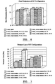
- CO 2 system performance in terms of both the coefficient of performance (COP), (defined as the ratio of cooling capacity to the power consumed for delivering the cooling effects) and cooling capacity, is critically sensitive to the refrigerant approach temperature at the gas cooler exit and pressure loss through the gas cooler.
- COP coefficient of performance
- the objective of a good gas cooler design is therefore to achieve the lowest approach temperature at possible minimum pressure loss, or the best combination of the two, to obtain the best system performance.
- a constraint of gas cooler design is that its physical dimension is usually limited by the under bonnet packaging space. Manufacturer requirements mean that the CO 2 gas cooler must be accommodated within the same packaging space as the condenser in prior art systems. In this spirit, many current gas cooler designs follow the current best condenser design practice of one-row, multipass parallel flow. This however does not take into account the significant difference between a conventional condenser and the gas cooler.
- the conventional refrigerant in a condenser flows mainly in two-phase state, and thus the refrigerant temperature over the majority of condenser is almost constant (changes very slightly due to a small pressure drop in the condenser).
- gas cooler In a gas cooler, the refrigerant flows in supercritical state without phase change and thus a significant temperature slide occurs over the refrigerant flow path. It follows that the optimal design for the gas cooler may be different from that of conventional condenser if this significant temperature slide is properly taken into account.
- the other disadvantage of gas cooler following a conventional one-row multipass condenser design is that it will result in very uneven air-off temperature from the gas cooler, which in extreme cases can lead to the heating up of part of the downstream vehicle radiator instead of cooling it, which could especially be a problem for unified gas cooler (condenser) and radiator.
- the present invention provides the designs that take into account of the particular characteristics of heat exchangers operating in supercritical state.
- the preferred design is a cross-counter flow, two tube length row, two pass heat exchanger 1.
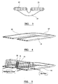
- the two rows 2, 3 of the tube lengths 4 are formed from a continuous single tube, turned and twisted back at a return portion 5 of the heat exchanger for the two rows of tube lengths to be parallel and in line.
- the return portion 5, as can be seen from the drawings, lies in the same plane, and has the same height (depth) dimension as the tube lengths as the tube lengths in rows 2, 3. This provides enhanced flow characteristics.
- the first row of tube length is connected to the collection header 6 and the second row connected to the distribution header 7.
- the two headers 6,7 are located on the same end of the heat exchanger and they are separated with a small gap (t) to prevent heat conduction between them.
- a non-conductive connection may be provided.
- a common airway 9 spanning the both tube rows is brazed to the two tube rows (as shown most clearly in Figure 5).
- the bridge region 10 of the airway falling between the regions of the two tube rows is cut with a region 11 of multiple narrow and long louvers or slits, which also promote local heat transfer to the air stream.
- the return portion of the tubes can be brazed to a plate.
- FIGS. 3 and 4 show a exemplary tube including forward and return lengths 12, 13 and tube return portion 15.
- a second embodiment of the present invention is a cross-counter flow, multiple row heat exchanger with headers (6, 7, 26, 27) at both ends.
- This design avoids the need to twist and turn the tubes and also provides flexibility of multiple pass arrangements in each individual row.
- headers (6, 7) that connect to each row of tubes separated from each other with a small gap (t).
- Common airways cut with narrow long louvers or slits between the bridge regions are brazed to the multiple rows of tubes as shown for the embodiment of Figures 1 and 5.
Landscapes
- Engineering & Computer Science (AREA)
- Physics & Mathematics (AREA)
- Thermal Sciences (AREA)
- Mechanical Engineering (AREA)
- General Engineering & Computer Science (AREA)
- Geometry (AREA)
- Heat-Exchange Devices With Radiators And Conduit Assemblies (AREA)
- Air-Conditioning For Vehicles (AREA)
Applications Claiming Priority (2)
| Application Number | Priority Date | Filing Date | Title |
|---|---|---|---|
| GB0306271 | 2003-03-19 | ||
| GB0306271A GB2400648A (en) | 2003-03-19 | 2003-03-19 | An automotive heat exchanger |
Publications (2)
| Publication Number | Publication Date |
|---|---|
| EP1460364A2 true EP1460364A2 (de) | 2004-09-22 |
| EP1460364A3 EP1460364A3 (de) | 2011-09-21 |
Family
ID=9955062
Family Applications (1)
| Application Number | Title | Priority Date | Filing Date |
|---|---|---|---|
| EP04251603A Withdrawn EP1460364A3 (de) | 2003-03-19 | 2004-03-19 | Wärmetauscher für ein Kraftfahrzeug |
Country Status (2)
| Country | Link |
|---|---|
| EP (1) | EP1460364A3 (de) |
| GB (1) | GB2400648A (de) |
Cited By (7)
| Publication number | Priority date | Publication date | Assignee | Title |
|---|---|---|---|---|
| DE10349150A1 (de) * | 2003-10-17 | 2005-05-19 | Behr Gmbh & Co. Kg | Wärmeübertrager, insbesondere für Kraftfahrzeuge |
| WO2007101817A1 (fr) * | 2006-03-07 | 2007-09-13 | Valeo Systemes Thermiques | Echangeur de chaleur, en particulier refroidisseur de gaz, comportant deux nappes de tubes reliées |
| WO2012041441A2 (fr) | 2010-09-30 | 2012-04-05 | Valeo Systems Thermiques | Echangeur de chaleur pour vehicule automobile. |
| WO2013001019A1 (fr) | 2011-06-28 | 2013-01-03 | Valeo Systemes Thermiques | Echangeur de chaleur, boitier et circuit de climatisation comprenant un tel echangeur |
| DE102015217031A1 (de) | 2015-09-04 | 2017-03-09 | BSH Hausgeräte GmbH | Kältegerät mit einem Kältemittelverdampfer |
| CN106524594A (zh) * | 2016-10-13 | 2017-03-22 | 杭州三花家电热管理系统有限公司 | 蛇形管式换热器 |
| WO2022137768A1 (ja) | 2020-12-25 | 2022-06-30 | 株式会社カネカ | 積層体およびその利用 |
Families Citing this family (1)
| Publication number | Priority date | Publication date | Assignee | Title |
|---|---|---|---|---|
| CN108630329B (zh) * | 2017-03-24 | 2024-05-31 | 国家电投集团科学技术研究院有限公司 | 安全壳内置换热器 |
Citations (5)
| Publication number | Priority date | Publication date | Assignee | Title |
|---|---|---|---|---|
| JPS58108394A (ja) * | 1981-12-21 | 1983-06-28 | Hitachi Ltd | 熱交換器 |
| EP0367078A1 (de) * | 1988-10-24 | 1990-05-09 | Sanden Corporation | Wärmeaustauscher |
| EP0431917A1 (de) * | 1989-12-07 | 1991-06-12 | Showa Aluminum Kabushiki Kaisha | Duplex-Wärmetauscher |
| JP2001248995A (ja) * | 2000-03-03 | 2001-09-14 | Zexel Valeo Climate Control Corp | 熱交換器 |
| JP2002181488A (ja) * | 2000-12-13 | 2002-06-26 | Japan Climate Systems Corp | 複合型熱交換器 |
Family Cites Families (11)
| Publication number | Priority date | Publication date | Assignee | Title |
|---|---|---|---|---|
| GB1481412A (en) * | 1974-07-26 | 1977-07-27 | Marston Radiators Ltd | Heat exchanger |
| US4770240A (en) * | 1985-05-13 | 1988-09-13 | Stark Manufacturing, Inc. | Manifold for a heat exchanger |
| JP3043050B2 (ja) * | 1990-11-22 | 2000-05-22 | 昭和アルミニウム株式会社 | 熱交換器 |
| US5314013A (en) * | 1991-03-15 | 1994-05-24 | Sanden Corporation | Heat exchanger |
| JP3305460B2 (ja) * | 1993-11-24 | 2002-07-22 | 昭和電工株式会社 | 熱交換器 |
| JP2000046441A (ja) * | 1998-07-28 | 2000-02-18 | Calsonic Corp | 炭酸ガス冷凍サイクル用熱交換器 |
| FR2793013B1 (fr) * | 1999-04-28 | 2001-07-27 | Valeo Thermique Moteur Sa | Echangeur de chaleur brase, en particulier pour vehicule automobile |
| DE19933913C2 (de) * | 1999-07-20 | 2003-07-17 | Valeo Klimatechnik Gmbh | Verdampfer einer Kraftfahrzeugklimaanlage |
| JPWO2003040640A1 (ja) * | 2001-11-08 | 2005-03-03 | 株式会社ゼクセルヴァレオクライメートコントロール | 熱交換器及び熱交換器用チューブ |
| US20030102113A1 (en) * | 2001-11-30 | 2003-06-05 | Stephen Memory | Heat exchanger for providing supercritical cooling of a working fluid in a transcritical cooling cycle |
| US20030106677A1 (en) * | 2001-12-12 | 2003-06-12 | Stephen Memory | Split fin for a heat exchanger |
-
2003
- 2003-03-19 GB GB0306271A patent/GB2400648A/en not_active Withdrawn
-
2004
- 2004-03-19 EP EP04251603A patent/EP1460364A3/de not_active Withdrawn
Patent Citations (5)
| Publication number | Priority date | Publication date | Assignee | Title |
|---|---|---|---|---|
| JPS58108394A (ja) * | 1981-12-21 | 1983-06-28 | Hitachi Ltd | 熱交換器 |
| EP0367078A1 (de) * | 1988-10-24 | 1990-05-09 | Sanden Corporation | Wärmeaustauscher |
| EP0431917A1 (de) * | 1989-12-07 | 1991-06-12 | Showa Aluminum Kabushiki Kaisha | Duplex-Wärmetauscher |
| JP2001248995A (ja) * | 2000-03-03 | 2001-09-14 | Zexel Valeo Climate Control Corp | 熱交換器 |
| JP2002181488A (ja) * | 2000-12-13 | 2002-06-26 | Japan Climate Systems Corp | 複合型熱交換器 |
Cited By (10)
| Publication number | Priority date | Publication date | Assignee | Title |
|---|---|---|---|---|
| DE10349150A1 (de) * | 2003-10-17 | 2005-05-19 | Behr Gmbh & Co. Kg | Wärmeübertrager, insbesondere für Kraftfahrzeuge |
| WO2007101817A1 (fr) * | 2006-03-07 | 2007-09-13 | Valeo Systemes Thermiques | Echangeur de chaleur, en particulier refroidisseur de gaz, comportant deux nappes de tubes reliées |
| FR2898405A1 (fr) * | 2006-03-07 | 2007-09-14 | Valeo Systemes Thermiques | Echangeur de chaleur, en particulier refroidisseur de gaz, comportant deux nappes de tubes reliees |
| WO2012041441A2 (fr) | 2010-09-30 | 2012-04-05 | Valeo Systems Thermiques | Echangeur de chaleur pour vehicule automobile. |
| WO2013001019A1 (fr) | 2011-06-28 | 2013-01-03 | Valeo Systemes Thermiques | Echangeur de chaleur, boitier et circuit de climatisation comprenant un tel echangeur |
| EP2726808B1 (de) | 2011-06-28 | 2016-07-06 | Valeo Systèmes Thermiques | Wärmetauscher, gehäuse und klimaanlagenkreis mit einem solchen wärmetauscher |
| US9958218B2 (en) | 2011-06-28 | 2018-05-01 | Valeo Systemes Thermiques | Heat exchanger, housing, and air-conditioning circuit comprising such an exchanger |
| DE102015217031A1 (de) | 2015-09-04 | 2017-03-09 | BSH Hausgeräte GmbH | Kältegerät mit einem Kältemittelverdampfer |
| CN106524594A (zh) * | 2016-10-13 | 2017-03-22 | 杭州三花家电热管理系统有限公司 | 蛇形管式换热器 |
| WO2022137768A1 (ja) | 2020-12-25 | 2022-06-30 | 株式会社カネカ | 積層体およびその利用 |
Also Published As
| Publication number | Publication date |
|---|---|
| GB2400648A (en) | 2004-10-20 |
| EP1460364A3 (de) | 2011-09-21 |
| GB0306271D0 (en) | 2003-04-23 |
Similar Documents
| Publication | Publication Date | Title |
|---|---|---|
| KR100638490B1 (ko) | 열교환기 | |
| CN100445687C (zh) | 用于热交换器的缝隙式散热片 | |
| US5086835A (en) | Heat exchanger | |
| EP2660550B1 (de) | Wärmetauscher und klimaanlage | |
| AU2002365762B2 (en) | Heat exchanger for providing supercritical cooling of a working fluid in a transcritical cooling cycle | |
| JP5585543B2 (ja) | 車両用冷却装置 | |
| CA2469733C (en) | Heat exchanger having non-perpendicularly aligned heat transfer elements | |
| JP2008503705A (ja) | 冷却システムで使用するための一体型の熱交換器 | |
| US20030183378A1 (en) | Heat exchanger and folded tube used therein | |
| EP1998133A1 (de) | Wärmetauscher und integrierter wärmetauscher | |
| US11656033B2 (en) | Combined core microchannel heat exchanger | |
| US20030041617A1 (en) | Cooling system for a vehicle | |
| CN114729793B (zh) | 传热管以及热交换器 | |
| EP1460364A2 (de) | Wärmetauscher für ein Kraftfahrzeug | |
| EP1479992A2 (de) | Wärmetauscher | |
| US20080184734A1 (en) | Flat Tube Single Serpentine Co2 Heat Exchanger | |
| US20070056718A1 (en) | Heat exchanger and duplex type heat exchanger | |
| CN113544458B (zh) | 气体集管、热交换器以及制冷循环装置 | |
| KR100638488B1 (ko) | 이산화탄소용 열교환기 | |
| EP4083555B1 (de) | Mikrokanalwärmetauscherabfluss | |
| US7650934B2 (en) | Heat exchanger | |
| JP2001165586A (ja) | 熱交換器および該熱交換器を備えた空調冷凍装置 | |
| US12305896B2 (en) | Heat exchanger and refrigeration cycle apparatus | |
| JP5238408B2 (ja) | 熱交換器 | |
| KR20050089497A (ko) | 열교환기 |
Legal Events
| Date | Code | Title | Description |
|---|---|---|---|
| PUAI | Public reference made under article 153(3) epc to a published international application that has entered the european phase |
Free format text: ORIGINAL CODE: 0009012 |
|
| AK | Designated contracting states |
Kind code of ref document: A2 Designated state(s): AT BE BG CH CY CZ DE DK EE ES FI FR GB GR HU IE IT LI LU MC NL PL PT RO SE SI SK TR |
|
| AX | Request for extension of the european patent |
Extension state: AL LT LV MK |
|
| PUAL | Search report despatched |
Free format text: ORIGINAL CODE: 0009013 |
|
| AK | Designated contracting states |
Kind code of ref document: A3 Designated state(s): AT BE BG CH CY CZ DE DK EE ES FI FR GB GR HU IE IT LI LU MC NL PL PT RO SE SI SK TR |
|
| AX | Request for extension of the european patent |
Extension state: AL LT LV MK |
|
| RIC1 | Information provided on ipc code assigned before grant |
Ipc: F28F 9/26 20060101ALI20110816BHEP Ipc: F28F 1/02 20060101ALI20110816BHEP Ipc: F28D 1/047 20060101AFI20110816BHEP |
|
| AKY | No designation fees paid | ||
| REG | Reference to a national code |
Ref country code: DE Ref legal event code: R108 |
|
| 17P | Request for examination filed |
Effective date: 20120323 |
|
| RBV | Designated contracting states (corrected) |
Designated state(s): AT BE BG CH CY LI |
|
| REG | Reference to a national code |
Ref country code: DE Ref legal event code: R108 Effective date: 20120530 |
|
| RBV | Designated contracting states (corrected) |
Designated state(s): AT BE BG CH CY CZ DE DK EE ES FI FR GB GR HU IE IT LI LU MC NL PL PT RO SE SI SK TR |
|
| 17Q | First examination report despatched |
Effective date: 20120816 |
|
| STAA | Information on the status of an ep patent application or granted ep patent |
Free format text: STATUS: THE APPLICATION IS DEEMED TO BE WITHDRAWN |
|
| 18D | Application deemed to be withdrawn |
Effective date: 20160127 |