EP1460377A2 - Procédé et dispositif pour traitement d'image dans un appareil de mesure géodésique - Google Patents
Procédé et dispositif pour traitement d'image dans un appareil de mesure géodésique Download PDFInfo
- Publication number
- EP1460377A2 EP1460377A2 EP03011908A EP03011908A EP1460377A2 EP 1460377 A2 EP1460377 A2 EP 1460377A2 EP 03011908 A EP03011908 A EP 03011908A EP 03011908 A EP03011908 A EP 03011908A EP 1460377 A2 EP1460377 A2 EP 1460377A2
- Authority
- EP
- European Patent Office
- Prior art keywords
- template
- image
- display
- recording
- image coordinate
- Prior art date
- Legal status (The legal status is an assumption and is not a legal conclusion. Google has not performed a legal analysis and makes no representation as to the accuracy of the status listed.)
- Withdrawn
Links
Images

Classifications
-
- G—PHYSICS
- G01—MEASURING; TESTING
- G01C—MEASURING DISTANCES, LEVELS OR BEARINGS; SURVEYING; NAVIGATION; GYROSCOPIC INSTRUMENTS; PHOTOGRAMMETRY OR VIDEOGRAMMETRY
- G01C11/00—Photogrammetry or videogrammetry, e.g. stereogrammetry; Photographic surveying
- G01C11/02—Picture taking arrangements specially adapted for photogrammetry or photographic surveying, e.g. controlling overlapping of pictures
-
- G—PHYSICS
- G01—MEASURING; TESTING
- G01C—MEASURING DISTANCES, LEVELS OR BEARINGS; SURVEYING; NAVIGATION; GYROSCOPIC INSTRUMENTS; PHOTOGRAMMETRY OR VIDEOGRAMMETRY
- G01C1/00—Measuring angles
- G01C1/02—Theodolites
- G01C1/04—Theodolites combined with cameras
-
- G—PHYSICS
- G01—MEASURING; TESTING
- G01C—MEASURING DISTANCES, LEVELS OR BEARINGS; SURVEYING; NAVIGATION; GYROSCOPIC INSTRUMENTS; PHOTOGRAMMETRY OR VIDEOGRAMMETRY
- G01C15/00—Surveying instruments or accessories not provided for in groups G01C1/00 - G01C13/00
- G01C15/02—Means for marking measuring points
Definitions
- the invention relates to a method and a device for geodetic measurement of an object with the aid of image processing using a geodetic measuring device.
- a large number of measuring devices have been known since ancient times for recording properties of defined points in a measurement environment, in particular data with spatial reference.
- the location of a measuring device along with any existing reference points, as well as direction, distance and angle to measuring points are recorded as spatial standard data. Improvements to date have mostly concerned the use of new technical processes with increased accuracy and speed.
- a geodetic device By combining a geodetic device with a screen that can be moved or moved independently of this device, advantages can be achieved in terms of ergonomics and measurement technology. It will Conventional eyepiece of the telescope replaced by electronic recording means, so that the previously necessary bond between the operator and the device, as well as the requirements or restrictions resulting from the use of the human eye can be removed.
- the device and the measurements to be carried out are controlled electronically via the display of the screen and a suitable input device for data and control commands. After alignment, the measurements can then be carried out using various methods, such as, for example, measuring the angular offset with additional distance measurement by triangulation or using a laser.
- the combination of a theodolite with a video camera is known from the patents JP 02130409 A and JP 03167412 A, with which fast and accurate three-dimensional measurements are to be made possible.
- Two theodolite video camera combinations are used to simultaneously record images by the respective camera and angle measurements using theodolites.
- the axes of the video camera and theodolite are parallel, so that the angle measurement of a theodolite is linked to the images recorded by the camera of this combination.
- the three-dimensional positions of the depicted objects can be derived from at least two images taken at different angles.
- the measuring device has a movable measuring head with a camera as target acquisition device and a distance measuring device, the target axes of which are precisely aligned with one another. On The target point is measured by capturing it with the camera and then aligning the camera axis with the target point. This also involves a precise alignment of the distance measuring device, so that its axis also points to the point to be measured.
- a geodetic device is known from the international PCT application WO 99/60335 which detects a target area with a camera and displays it on a screen. Within this range, targets can be selected and their distance can be measured by a range finder by aligning the range finder as a complete device with its axis to the selected target. In doing so Camera and rangefinder either moved together or independently by motors.
- a geodetic measuring device in which a movement of the beam required for the measurement is effected within the detection range of an optical system, without requiring an otherwise necessary movement of the entire optical system or larger components.
- optical components of the electronic recording means to emit the radiation beam.
- the radiation emitted via the optics of the recording means can be used to measure all of the targets that are detected and shown in the illustration without the optical axis of the recording means or another independent component of the measuring device having to be moved.
- the recording means relate to the devices for image generation that are used to determine the target point for a measuring point.
- the detectors required to carry out the measurement can also be installed in other measuring devices, so that, for example, a measuring device with such an electronic display and control device determines and illuminates a target with radiation, but the measurement is carried out by one or more further devices ,
- a further disadvantage is the necessity that each device must have its own directing means in order to align the axis of the measuring device or the measuring radiation with a target. Even if all of the targets for a special measurement task are always within the detection range of the recording device, point-by-point alignment or aiming and subsequent measurement must be carried out for each measurement process.
- the special design of target points to be measured e.g. by using reflectors as so-called cooperative goals
- an at least partially automated measurement can be achieved.
- this requires attaching the cooperative goals to be measured to the points to be measured, which is particularly reflected in increased effort.
- the use of cooperative goals is not possible under all circumstances, e.g. when measuring inaccessible places.
- the automated target search and alignment process also requires increased technical and time expenditure.
- One task is to enable semi-automated measurement of non-cooperative, but structured goals.
- Another object is to enable non-cooperative targets to be measured within a certain range without mechanical adjustment of a component of the measuring device.
- Another task is to simplify the construction of a generic geodetic measuring device.
- Another task is to reduce the time and energy expenditure when using a generic geodetic measuring device.
- the solution uses the electronic recording of a captured observation area.
- image data are used, which were recorded with a geodetic measuring device, for example a theodolite or tachymeter.
- the entire measuring device / image sensor system must be calibrated so that the image data can be used to measure the object.
- Such a video measuring device system can now be used to measure any structured objects.
- the surveyor is no longer dependent on an active or cooperative target to carry out a semi-automated point determination.
- an ideal link is achieved, on the one hand, between human control and, on the other hand, the reliability of algorithms.
- Templates in the form of templates that at least partially describe the object to be measured support the surveyor in selecting the target points of the objects to be measured. If necessary, the 3rd dimension of the object is determined by means of a reflectorless distance measurement.
- the term “geodetic measuring device” is always to be understood generally as a measuring instrument which has devices for measuring or checking data with spatial reference. In particular, this relates to the measurement of directions or angles and / or distances to a reference or measurement point.
- other devices e.g. Components for satellite-based location determination (e.g. GPS, GLONASS or GALILEO) are available, which can be used for additional measurements or data recordings.
- GPS Globalstar, GLONASS or GALILEO
- such a geodetic measuring device should be understood to mean theodolites, so-called total stations as tachymeters with electronic angle measurement and electro-optical range finders, and levels.
- the invention is suitable for use in specialized devices with similar functionality, e.g. in military directional circles or in industrial building or process monitoring. These systems are hereby also included under the term "geodetic measuring device”.
- the geodetic measuring device has electronic recording means, which record objects, especially an object to be measured, in the form of a recording image within a detection strip.
- the recording means include, for example, a CCD camera, a CMOS camera, a video camera, a residual light amplifier or a thermal imaging camera.
- the exact angular orientation of the detection strip is determined by preferably determining the orientation of the recording means and / or a lens of the recording means by means of angle encoders of the geodetic measuring device. A captured image or a partial area of this image is made visible in the form of a display image using display means.
- the means of representation have in particular an LC display, a cathode ray tube, a flat screen, an interface to communication networks and / or an electronic computer with a screen, preferably designed as a notebook or laptop.
- at least one display image coordinate is defined, for example by positioning a cursor on the display means. Positioning takes place in particular via input means, for example in the form of a keyboard field, a joy stick, a trackball, a computer mouse, a touch-sensitive input field, an interface to communication networks and / or via a unit combined with the display means, in particular a touch-sensitive screen or an electronic computer with an input device, preferably designed as a notebook, laptop or handheld PC, in particular a Palm PC.
- the specified display image coordinate is assigned directly or indirectly to a recorded image coordinate, which in turn is transformed into at least one geodetic measurement variable, in particular a solid angle, preferably a horizontal and a vertical angle.
- the transformation takes place taking into account the recording image coordinate, the angular orientation of the detection strip of the recording means, the focus position, the imaging scale, the optical errors and / or the temperature-dependent deposits.
- the geodetic measurement variable means, for example, on the one hand the coordinates or components of a point in any coordinate system, in particular a polar coordinate system, and on the other hand relative relationships between individual points, in particular distances or angles between object points.
- the recording image coordinate is preferably determined by the surveyor first calling up a template in the form of a template which at least partially models the object to be measured geodetically.
- the template is positioned approximately on the display image, e.g. by the surveyor defines at least one display image coordinate by positioning a cursor on the display means.
- the approximately positioned template is adapted to the recorded object to be geodetically measured, in particular using matching. If necessary after selecting a characteristic point of the adapted template, for example an end point, corner point, intersection point, center point, etc., the image coordinate is determined, after which the transformation mentioned above is carried out.
- the described method according to the invention is stored, for example, in the form of a computer program product, in particular as software or firmware, and is carried out by computing means, in particular a personal computer, a laptop, a notebook, a single-board computer or another electronic computing and control unit.
- computing means in particular a personal computer, a laptop, a notebook, a single-board computer or another electronic computing and control unit.
- the data and results of the measurement process can be displayed on the display means.
- This representation is in the form of an overlay font or in own display fields possible.
- the latter can be designed as separate parts of the screen, which, for example, represent enlarged image sections.
- a touch-sensitive flat screen also makes it possible to dispense with special input means, so that the display and input means can be made compact and modular.
- a further possibility of realizing the representation or input means consists in the connection to devices which can also be used for other applications.
- additional functionalities can be accessed via an interface for communication networks or the use of a standard computer, in particular a portable laptop or notebook.
- a standard computer in particular a portable laptop or notebook.
- additional, possibly universally applicable software can be used.
- recorded measurement data can be stored immediately in the available memories and, after disconnection from the geodetic measuring device, also used in other applications.
- a measuring device can also be placed in areas that were previously not usable, e.g. in corners or narrow passages.
- a connection to the geodesic Measuring device which now essentially only consists of a housing and the components of the lens with sensor elements together with the associated control components, can be produced by means of communication, for example wire or radio connections.
- wire connections should always be understood to mean all flexible communication connections which are used for the transmission of data, but in particular glass fiber and copper cables.
- This separation also allows the control of a large number of geodetic measuring devices as pure sensor units by means of a central control and evaluation unit.
- the latter can be protected from the weather e.g. be housed in a vehicle.
- the accommodation in a vehicle also allows the use of additional components that would prohibitively increase its weight when attached to the individual measuring device.
- the use of multiple sensor units allows simplified, simultaneous measurements on common or different points, an alignment of the geodetic measuring devices with each other or a rollover, in which only one part of the sensor units is always used for measurements, while the other part is moved to other locations.
- the display of the measuring ranges of sensor units used at the same time can be shown one after the other on the same screen or at the same time on a screen in separate display areas, e.g. using window or split-screen technology.
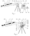
- the geodetic measuring device 2 has a pivotable axis 24 and a tiltable axis 25 Optics unit 19 with recording means 3, here designed as a CCD or CMOS camera arranged instead of an eyepiece.
- the geodetic measuring device 2 also has an external distance meter 20 for reflectorless distance measurement and / or for focusing the optical unit 19.
- the geodetic measuring device 2 is a so-called tachymeter.
- the recording means 3 record a scene 23 which has at least one object 1 to be measured geodetically, which is symbolized in FIG. 1 by the six trees.
- the detection strip 5 can be aligned by rotating or tilting the optical unit 19 including the receiving means 3 about the standing axis 24 and the tilting axis 25 and, if necessary, by changing the imaging scale of the Optics unit 19 variable in size.
- the alignment of the detection strip 5 thus results from the alignment of the optical unit 19 and is determined via angle encoders (not shown) which are integrated in the geodetic measuring device 2.
- the image 4 is forwarded to the electronic display and control device 31 by means of a signal via a wire connection 22.
- a radio connection or transmission via communication networks such as the Internet can be implemented.
- This electronic display and control device 31 comprises electronic calculation means 32, electronic representation means 33, input means 34 and a template memory 35.
- the recording image 4 a detail, an enlargement or a reduction of the recording image 4 is visualized in the form of a representation image 6 by the representation means 33 shown, which contains at least the recorded, to be geodetically measured object 1a, here the one tree.
- a coordinate on the display image 6, hereinafter referred to as the display image coordinate 8 can be determined via the input means 34, for example by positioning a cursor that can be moved using a joystick or a mouse.
- the input means 34 to provide data such as coordinates, zoom settings, alignment settings of the geodetic measuring device 2 and further data and commands, in particular for the selection of Selection aids in the form of templates to be entered in the calculation means 32.
- the calculation means 32 execute a program according to software and / or firmware and are formed, for example, by a CPU.
- the template memory 35 serves to store at least one template, for example in the form of a graphic template, the template at least partially modeling the object to be measured geodetically.
- the function of the template memory 35 is described in more detail below.
- a modified Leica tachymeter TCXA110x for the recording of the image.
- the eyepiece is replaced by a CCD camera as the recording means 3, a suitable imaging sensor being used for series production.
- Automatic focusing is made possible by installing a motor in the telescope which forms the optical unit 19. The focus can be applied both to the entire scene 23 and to defined sections. A possible system can also focus on certain objects. Alternatively or in the case of simple systems, the user can also focus by hand.
- FIG. 2 shows a possible, alternative embodiment of the system from FIG. 1, in which a geodetic measuring device 2 'and an electronic display and control device 31' are designed as a common integrated unit.
- the geodetic measuring device 2 ' has an optical unit 19' which can be aligned about a standing axis 24 and a tilting axis 25, with recording means 3 'for detecting a scene 23 an object 1 to be measured geodetically within a detection strip 5.
- the display and control device 31 ' is arranged directly on or within the same housing of the geodetic measuring device 2' and contains the calculation means 32 ', the display means 33', the input means 34 'and the template memory 35' in a single device.
- the display means 33 ' which reproduce at least a part of the scene within the detection strip 5 in the form of at least the depicted object 1a, are designed in this embodiment as a touch-sensitive TFT / LCD screen and thus also represent the input means 34' through which Touching the screen either manually or by means of a pen 36 can directly define a display coordinate 8 'in the display 6'.
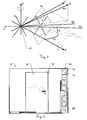
- Fig. 3 shows the transformation model for transforming a captured image coordinate of the captured image 4 into the polar angle of a captured object 1 with an object point Q.
- the polar angle of any object point Q within the detection strip 5 based on its position on the captured image 4, which is from the image sensor Recording means 3 is detected, and thus can be determined on the basis of its recording image coordinate, a mathematical description of the mapping of scene 23 onto the recording image 4 must be known.
- the transformation of points in the recorded image coordinate system x, y, z into the object coordinate system X, Y, Z will be described below with reference to FIG. 3.
- the axis Z points in the direction of the zenith and represents the piercing axis 24, the axis X is formed by the tilting axis 25.
- the optical axis 42 is defined as the axis through the optical unit 19 and thus essentially the axis that passes through the centers of the lenses.
- the theodolite axis 43 is defined as the axis with respect to which the angles of rotation about the standing axis 24 and the tilt axis 25 are measured. This means that the intersection of the theodolite axis 43 with the image sensor of the recording means 3 points exactly at the object point Q of the object 1 to be measured in a two-layer measurement. This corresponds to the target axis with respect to the crosshairs in optical theodolites.
- the calculations are limited to the mapping of an object point Q in a superordinate coordinate system, which is horizontal and whose origin lies in the projection center 41, into the image plane of the captured image 4.
- a transfer to any coordinate system can be carried out by means of displacement and rotation using the known Helmert transformation with a scale of one.
- the temperature calibration is described below.
- the temperature calibration of the entire system is carried out analogously to the calibration of an optical theodolite.
- the advantage of an image-supported system is that the object no longer has to be sighted manually in both positions, but that the system uses image analysis to determine the polar angle of the object.
- the geodetic measuring device can be aligned very precisely, in the range of a few cc, to the object.
- the offset between a crosshair defining the target axis and an object point on the image sensor of the recording means 3 is determined by means of the above-mentioned model. Uncertainties in the model parameters can be neglected because the stores are very small.
- the chamber constant of the system defined above For the conversion of the pixel deposits on the image 4 into the polar angle of the object 1 to be measured geodetically, it is necessary to know the chamber constant of the system defined above from the optical unit 19 and the recording means 3. For this purpose, the best focus position of the optical unit 19 is determined for a target within the detection strip 5 at different distances. Based on a mathematical model of the optical design, parameters are determined that make it possible to derive the chamber constant from any focus position.
- An online method makes it possible to determine the imaging scale of the optical image, which is directly coupled to the chamber constant, during a measurement. by virtue of the displacement of an object point within the detection strip 5 on the image sensor of the recording means 3 as a result of a movement of the optical unit 19 and the recording means 3, the imaging scale can be determined.
- the method is based on a very precise determination of the object in two or more images for different positions of the geodetic measuring device 2.
- the object determination is carried out by means of an image matching method.
- a stationary object is scanned with the geodetic measuring device 2.
- the geodetic measuring device 2 is positioned such that the object moves over the image sensor of the recording means 3.
- the images are taken in both positions of the optical unit, comparable to both theodolite telescope positions.
- the positions of the object on the image sensor of the recording means 3 are determined via image analysis.
- the template matching method is a suitable method.
- the transformation parameters are determined from the horizontal and vertical angles measured by means of the geodetic measuring device 2 and the corresponding object positions on the image sensor of the recording means 3.
- the axis errors are directly determined in this calibration with regard to the optical axis.
- the measuring process is largely automated by image processing, so that the user only has to aim at each target in the first position.
- the system learns the targets and then measures them automatically in both positions.
- the semi-automated measurement is based on a constant interaction between user and device. This means that the user defines what is to be measured and the measuring system carries out the actual measurement without necessarily moving mechanical parts.
- the measurement process is structured hierarchically. First, the user selects a template in the form of a template from a menu, which template describes the shape of the object to be measured. He now has the option to place the template approximately on the depicted object or to select from automatically found objects. By selecting the template, both the global and the local structure of the target can be defined.
- the measuring system performs a local matching in the range of a few pixels in order to determine the position and the direction of an object point in the image.
- the reflectorless distance meter 20 is used.
- the user can define the positioning of a laser of the distance meter 20 manually or automatically via the image evaluation. This should be illustrated using an example from FIGS. 4 to 8 become.
- the aim of this exemplary measurement is to determine a door frame or a corner of the door frame.
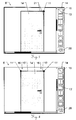
- the display image 6 ′′ shows a display image 6 ′′ shown on the display means 33 with a recorded object 1 a ′ to be measured in the form of a door.
- the display image 6 ′′ also shows a selection menu 14 which provides the user with a number of selectable menu items 15, which selection - Graph 13 in the form of different templates.
- the user defines a display image coordinate 8 "in the corner of the door 1a 'to be measured by placing a cursor by moving the cursor describing the display image coordinate 8" pixel by pixel on the display means 33 using the input means 34 ,
- the calculation means 32 determine, from the representation image coordinate 8 ′′ thus determined, a recording image coordinate 7 which results from the image section of the representation image 6 ′′ in relation to the recording image 4, in particular from the enlarged view and the section.
- this image coordinate 7 is transformed into a polar angle, in particular taking into account the angular orientation of the detection strip 5 of the recording means 3, the temperature and the optical errors, and the result of the transformation in the form of a display window 26 on the image 6 "
- a distance measurement is also carried out by the distance meter 20 measuring the distance to the object point with the determined polar angle, and the result of this distance measurement is also displayed in the display window 26.
- the object point to be measured is determined with the aid of at least one template 10 which at least partially models the recorded object 1 a 'to be measured - here the upper right corner of the door.
- the user selects a suitable selection template 13 from the menu items 15 of the selection menu 14, in this case a polyline. He then places the selected template 10 roughly on the object to be measured 1a ', that is to say on the upper right corner of the door, as shown in FIG. 5, by specifying a plurality of display image coordinates using the input means 34, for example with the aid of a cursor.
- Template 10 is used to determine the object in the image with sub-pixel accuracy. For this purpose, local matching is first carried out using the calculation means 32.
- the matching points are identified in FIG. 6 by matching points 17, the direction of the edge by direction vectors 18. Based on the local matching points, lines 21 are now fitted, as shown in FIG. 7.
- the intersection of the straight line 21 represents a characteristic point 11 of the template 10, which now has a sub-pixel accuracy of an image coordinate 7 and, according to the method described above, a polar coordinate of the object to be measured, here the top right corner of the door, possibly including the distance, is assigned.
- the user selects a template that at least partially models the object to be measured by selecting a selection template, whereupon the calculation means 32 search for structures in the captured image that match the template 10 ' are similar.
- the user selects a corner selection template as template 10 ' 13 ', whereupon the calculation means 32 automatically search for corner structures in the recorded object 1a' via matching.
- the template 10 ' is automatically placed on these structures 16 found by the calculation means.
- the characteristic points 11 ' are in each case the corner point of the template 10'. After the user has selected one of these characteristic points 11 ′, as described above, the polar angle and, if appropriate, the distance of the object point are determined after determining the corresponding image coordinate 7.
- characteristic points 11, 11' may be provided per template 10, 10 ', for example end points, corner points, center points and intersection points.
- the user has a certain range of selection templates 13, 13 'available. These different selection templates 13, 13 'are stored in a template memory 35.
- the user has three options for generating the template.
- Second, an artificially generated pixel image of an object can be used as a template 10, 10 ', a displacement of the template 10, 10' in the sub-pixel area being determined by interpolation.
- the third possibility is the mathematical description of the object, from which the template 10, 10 'can be calculated for any image position.
- Template memory 35 which can be embodied as a known data memory, takes place either as a pixel image, which can be reduced in scope by suitable compression methods, or as a mathematical description, whereby template 10, 10 'is calculated online using a suitable algorithm and is not permanent is saved.
- the described method can be stored as a program, in particular in the form of a computer program product which can be read and executed by the computing means 32 as software, for example on a floppy disk, CD or hard disk. It is also possible to save the program as firmware, for example on an EPROM, an electronically programmable read-only memory, of the calculation means 32.
- the advantages of the system and method according to the invention are, in particular, that the human being is involved in the measurement process and can control the system directly, as a result of which an ideal link between the control by the user and the reliability of algorithms is achieved.
- the system only measures the relevant points that are necessary to determine the object. Compared to a scanner that scans all points, an intelligent measurement is carried out, which also leads to a significant reduction in data. On the other hand, as many pixels as possible are used locally. This achieves redundancy in the description of the object.
- the system is also multifunctional in that both 3D points and three-dimensional objects such as straight lines can be measured using image evaluation. It is also possible to save image data for documentation purposes. There is also the option of viewing the images at a later date Use to determine the horizontal and vertical angles of other points. The 3D determination becomes possible if the plane in which the points lie is known.
- the invention is suitable for use in a wide variety of applications.
- the monitoring of certain objects can be largely automated with the system according to the invention without the need to place target marks or prisms in the area to be monitored.
- the user roughly aims at the object to be monitored so that it is visible on the image. A diopter or a laser pointer can be used for this. Then it focuses on what can be done manually or automatically.
- the object is saved as a template.
- the target can now be measured again and again without the user having to intervene. An alarm is triggered as soon as a deviation is found above a predetermined threshold.
- the advantage over known methods is the extensive automation without the use of artificial target marks.
- the measurement can be partially automated by interaction with the user.
- the user aims at the object with the geodetic measuring instrument in wide-angle mode and designates all points to be measured in the image. Identification can be done by placing templates. Parameters can be specified for the points, for example that some points lie in a plane or on a straight line. With this additional information it is possible to accelerate the measuring process. In addition to the 3D Information is then also given about possible deviations from the ideal position.
- target tracking of non-cooperative objects can also be realized.
- the object structure is saved again and then iteratively identified in the image and the position determined.
Landscapes
- Engineering & Computer Science (AREA)
- Physics & Mathematics (AREA)
- General Physics & Mathematics (AREA)
- Radar, Positioning & Navigation (AREA)
- Remote Sensing (AREA)
- Multimedia (AREA)
- Image Processing (AREA)
- Length Measuring Devices By Optical Means (AREA)
- Image Analysis (AREA)
- Studio Devices (AREA)
Priority Applications (7)
| Application Number | Priority Date | Filing Date | Title |
|---|---|---|---|
| AU2004221661A AU2004221661B2 (en) | 2003-03-21 | 2004-03-18 | Method and device for image processing in a geodesical measuring appliance |
| US10/548,887 US7633610B2 (en) | 2003-03-21 | 2004-03-18 | Method and device for image processing in a geodetic measuring instrument |
| EP04721531.4A EP1606581B8 (fr) | 2003-03-21 | 2004-03-18 | Procede et dispositif de traitement d'image d'un appareil de mesure geodesique |
| CN2004800076448A CN1761855B (zh) | 2003-03-21 | 2004-03-18 | 大地测量仪器中的图像处理方法和装置 |
| CA2519431A CA2519431C (fr) | 2003-03-21 | 2004-03-18 | Procede et dispositif de traitement d'image d'un appareil de mesure geodesique |
| PCT/EP2004/002800 WO2004083779A1 (fr) | 2003-03-21 | 2004-03-18 | Procede et dispositif de traitement d'image d'un appareil de mesure geodesique |
| JP2006504718A JP4607095B2 (ja) | 2003-03-21 | 2004-03-18 | 測量機器において画像処理を行う方法と装置 |
Applications Claiming Priority (2)
| Application Number | Priority Date | Filing Date | Title |
|---|---|---|---|
| US45637103P | 2003-03-21 | 2003-03-21 | |
| US456371P | 2003-03-21 |
Publications (2)
| Publication Number | Publication Date |
|---|---|
| EP1460377A2 true EP1460377A2 (fr) | 2004-09-22 |
| EP1460377A3 EP1460377A3 (fr) | 2004-09-29 |
Family
ID=32825463
Family Applications (2)
| Application Number | Title | Priority Date | Filing Date |
|---|---|---|---|
| EP03011908A Withdrawn EP1460377A3 (fr) | 2003-03-21 | 2003-05-27 | Procédé et dispositif pour traitement d'image dans un appareil de mesure géodésique |
| EP04721531.4A Expired - Lifetime EP1606581B8 (fr) | 2003-03-21 | 2004-03-18 | Procede et dispositif de traitement d'image d'un appareil de mesure geodesique |
Family Applications After (1)
| Application Number | Title | Priority Date | Filing Date |
|---|---|---|---|
| EP04721531.4A Expired - Lifetime EP1606581B8 (fr) | 2003-03-21 | 2004-03-18 | Procede et dispositif de traitement d'image d'un appareil de mesure geodesique |
Country Status (7)
| Country | Link |
|---|---|
| US (1) | US7633610B2 (fr) |
| EP (2) | EP1460377A3 (fr) |
| JP (1) | JP4607095B2 (fr) |
| CN (1) | CN1761855B (fr) |
| AU (1) | AU2004221661B2 (fr) |
| CA (1) | CA2519431C (fr) |
| WO (1) | WO2004083779A1 (fr) |
Cited By (4)
| Publication number | Priority date | Publication date | Assignee | Title |
|---|---|---|---|---|
| US7623224B2 (en) | 2003-12-16 | 2009-11-24 | Trimble Jena Gmbh | Calibration of a surveying instrument |
| CN101975570A (zh) * | 2010-09-30 | 2011-02-16 | 大连理工大学 | 一种冲刷地形的三维观测装置 |
| WO2011141447A1 (fr) | 2010-05-10 | 2011-11-17 | Leica Geosystems Ag | Procédé de télémétrie |
| WO2017005439A1 (fr) * | 2015-07-08 | 2017-01-12 | Robert Bosch Gmbh | Mesure de longueur sur un objet par relèvement de points de mesure au moyen d'un module de mesure laser |
Families Citing this family (59)
| Publication number | Priority date | Publication date | Assignee | Title |
|---|---|---|---|---|
| US7800758B1 (en) * | 1999-07-23 | 2010-09-21 | Faro Laser Trackers, Llc | Laser-based coordinate measuring device and laser-based method for measuring coordinates |
| EP1515152A1 (fr) * | 2003-09-12 | 2005-03-16 | Leica Geosystems AG | Procède pour la détermination de la direction d'un objet a mesurer |
| EP1681533A1 (fr) * | 2005-01-14 | 2006-07-19 | Leica Geosystems AG | Procédé et dispositif géodésique pour arpenter aux moins une cible |
| US7292319B1 (en) * | 2005-05-24 | 2007-11-06 | Lockheed Martin Corp. | Optical tracking device employing a three-axis gimbal |
| US7933001B2 (en) * | 2005-07-11 | 2011-04-26 | Kabushiki Kaisha Topcon | Geographic data collecting system |
| ATE459858T1 (de) * | 2005-09-12 | 2010-03-15 | Trimble Jena Gmbh | Vermessungsinstrument und verfahren zur bereitstellung von vermessungsdaten mithilfe des vermessungsinstruments |
| US8060344B2 (en) * | 2006-06-28 | 2011-11-15 | Sam Stathis | Method and system for automatically performing a study of a multidimensional space |
| JP2008014653A (ja) * | 2006-07-03 | 2008-01-24 | Pentax Industrial Instruments Co Ltd | 測量機 |
| JP5150307B2 (ja) * | 2008-03-03 | 2013-02-20 | 株式会社トプコン | 地理データ収集装置 |
| JP5150310B2 (ja) * | 2008-03-04 | 2013-02-20 | 株式会社トプコン | 地理データ収集装置 |
| EP2219011A1 (fr) | 2009-02-11 | 2010-08-18 | Leica Geosystems AG | Appareil de mesure géodésique |
| DE202010017889U1 (de) * | 2010-03-15 | 2013-02-26 | Ulrich Clauss | Anordnung zur Aufnahme geometrischer und photometrischer Objektdaten im Raum |
| US20120320193A1 (en) | 2010-05-12 | 2012-12-20 | Leica Geosystems Ag | Surveying instrument |
| US9041796B2 (en) | 2010-08-01 | 2015-05-26 | Francis Ruben Malka | Method, tool, and device for determining the coordinates of points on a surface by means of an accelerometer and a camera |
| JP5698480B2 (ja) | 2010-09-02 | 2015-04-08 | 株式会社トプコン | 測定方法及び測定装置 |
| GB2483721A (en) * | 2010-09-20 | 2012-03-21 | Witold Marian Gamski | Survey tool for assessing construction or maintenance jobs |
| US9239232B2 (en) * | 2011-01-10 | 2016-01-19 | Trimble Ab | Method and system for determining position and orientation of a measuring instrument |
| EP2474808A1 (fr) | 2011-01-10 | 2012-07-11 | Leica Geosystems AG | Appareil de mesure géodésique doté d'une caméra thermographique |
| CN102589523A (zh) * | 2011-01-11 | 2012-07-18 | 香港理工大学深圳研究院 | 远距离监测建筑物位移的方法和所用装备 |
| EP2474810A1 (fr) * | 2011-01-11 | 2012-07-11 | Leica Geosystems AG | Appareil de mesure doté d'une fonctionnalité de pointage dynamique |
| US8539685B2 (en) | 2011-01-20 | 2013-09-24 | Trimble Navigation Limited | Integrated surveying and leveling |
| US10965889B2 (en) * | 2011-06-20 | 2021-03-30 | Fluke Corporation | Thermal imager that analyzes temperature measurement calculation accuracy |
| EP2543960A1 (fr) * | 2011-07-05 | 2013-01-09 | Hexagon Technology Center GmbH | Procédé de préparation de candidats de points cible pour la sélection d'un point cible |
| EP2551636A1 (fr) * | 2011-07-25 | 2013-01-30 | Leica Geosystems AG | Dispositif de mesure pouvant être commandé sans contact et son procédé de commande |
| EP2557392A1 (fr) | 2011-08-11 | 2013-02-13 | Leica Geosystems AG | Dispositif de mesure et procédé doté d'une fonctionnalité de ciblage échelonnable et basée sur l'orientation d'une unité de télécommande |
| DE102011114115A1 (de) * | 2011-09-25 | 2013-03-28 | Zdenko Kurtovic | Verfahren und Anordnung zur Bestimmung der Lage eines Meßpunktes im geometrischen Raum |
| CN103827631B (zh) * | 2011-09-27 | 2016-11-16 | 莱卡地球系统公开股份有限公司 | 对坐标系中已知的目标点进行标记的测量系统和方法 |
| US9222771B2 (en) | 2011-10-17 | 2015-12-29 | Kla-Tencor Corp. | Acquisition of information for a construction site |
| US9001205B2 (en) * | 2011-10-20 | 2015-04-07 | Trimble Navigation Ltd. | System and methods for controlling a surveying device |
| EP2662705A1 (fr) | 2012-05-07 | 2013-11-13 | Hexagon Technology Center GmbH | Appareil de surveillance comportant une caméra de portée |
| US8937725B2 (en) * | 2012-06-14 | 2015-01-20 | Nikon Corporation | Measurement assembly including a metrology system and a pointer that directs the metrology system |
| DE102012217282B4 (de) * | 2012-09-25 | 2023-03-02 | Trimble Jena Gmbh | Verfahren und Vorrichtung zur Zuordnung von Messpunkten zu einem Satz von Festpunkten |
| US9057610B2 (en) * | 2012-11-03 | 2015-06-16 | Trimble A.B. | Robotic laser pointer apparatus and methods |
| US9560246B2 (en) * | 2012-12-14 | 2017-01-31 | The Trustees Of Columbia University In The City Of New York | Displacement monitoring system having vibration cancellation capabilities |
| DE102013016486A1 (de) * | 2013-09-13 | 2015-04-02 | Stephan Hörmann | Vermessungsverfahren für Gebäudeöffnungen und Gebäudeabschlussherstellverfahren sowie Vorrichtungen zur Durchführung derselben |
| US9074892B2 (en) | 2013-03-15 | 2015-07-07 | Ian Michael Fink | System and method of determining a position of a remote object |
| DE102013205593A1 (de) * | 2013-03-28 | 2014-10-02 | Hilti Aktiengesellschaft | Verfahren und Vorrichtung zur Anzeige von Objekten und Objektdaten eines Konstruktionsplans |
| EP2787323A1 (fr) * | 2013-04-05 | 2014-10-08 | Leica Geosystems AG | Appareil de mesure doté d'une fonction de calibrage d'une position d'image d'indication d'un réticule à croisillon électronique |
| EP2787321B1 (fr) * | 2013-04-05 | 2015-09-16 | Leica Geosystems AG | Détermination de surface d'objets à l'aide de la détermination d'un seul point précis géodésique et du balayage |
| CN103217143A (zh) * | 2013-04-09 | 2013-07-24 | 上海电机学院 | 雷达装置及目标物体跟踪方法 |
| US9355495B2 (en) | 2013-10-09 | 2016-05-31 | Trimble Navigation Limited | Method and system for 3D modeling using feature detection |
| CN104374538A (zh) * | 2014-12-19 | 2015-02-25 | 广州大学 | 一种多维振动测试系统 |
| CN106802146A (zh) * | 2016-12-07 | 2017-06-06 | 北京唐浩电力工程技术研究有限公司 | 一种风机位置选址方法 |
| EP3583385B1 (fr) | 2017-02-14 | 2021-04-21 | Trimble AB | Étude géodésique avec synchronisation temporelle |
| US10791275B2 (en) * | 2017-09-25 | 2020-09-29 | The Boeing Company | Methods for measuring and inspecting structures using cable-suspended platforms |
| JP6942594B2 (ja) | 2017-09-29 | 2021-09-29 | 株式会社トプコン | スキャン範囲設定方法およびそのための測量システム |
| KR101836926B1 (ko) * | 2017-12-05 | 2018-04-19 | 한국지질자원연구원 | 트렌치 단면 기준선 설정 장치 및 이를 이용한 트렌치 단면 분석 방법 |
| RU2677089C1 (ru) * | 2018-04-24 | 2019-01-15 | федеральное государственное бюджетное образовательное учреждение высшего образования "Санкт-Петербургский горный университет" | Способ горизонтальной соединительной съемки подэтажных горизонтов |
| US10769813B2 (en) * | 2018-08-28 | 2020-09-08 | Bendix Commercial Vehicle Systems, Llc | Apparatus and method for calibrating surround-view camera systems |
| EP3623843B1 (fr) | 2018-09-11 | 2021-01-13 | Leica Geosystems AG | Appareil de mesure de distance laser portatif |
| US10708507B1 (en) * | 2018-10-11 | 2020-07-07 | Zillow Group, Inc. | Automated control of image acquisition via use of acquisition device sensors |
| US12008679B2 (en) | 2018-12-13 | 2024-06-11 | Leica Geosystems Ag | Measurement method, measurement systems and auxiliary measurement instruments for displaying desired positions in a live image |
| WO2020119912A1 (fr) * | 2018-12-13 | 2020-06-18 | Leica Geosystems Ag | Dispositif de mesure, système de mesure et instruments d'aide à la mesure |
| CN113466233B (zh) * | 2020-03-31 | 2024-07-16 | 北京配天技术有限公司 | 视觉检测方法、视觉检测装置及计算机存储介质 |
| JP7591910B2 (ja) * | 2020-11-26 | 2024-11-29 | 株式会社トプコン | 測量装置及び測量方法及び測量プログラム |
| JP7695093B2 (ja) * | 2021-03-29 | 2025-06-18 | 株式会社トプコン | 測量システム及び点群データ取得方法及び点群データ取得プログラム |
| CN113470017B (zh) * | 2021-08-31 | 2021-11-16 | 海门裕隆光电科技有限公司 | 基于人工智能的输电线安全预警检测方法、装置及设备 |
| US12175557B2 (en) | 2022-04-29 | 2024-12-24 | Trimble Inc. | Correcting position of a mobile device using a mobile reference |
| CN116929311B (zh) * | 2023-09-19 | 2024-02-02 | 中铁第一勘察设计院集团有限公司 | 变焦成像的断面变形监测方法、装置、系统及存储介质 |
Family Cites Families (15)
| Publication number | Priority date | Publication date | Assignee | Title |
|---|---|---|---|---|
| JPH02130409A (ja) | 1988-11-11 | 1990-05-18 | Taisei Corp | テレビ経緯儀による三次元測定方法と装置 |
| JP2686664B2 (ja) | 1989-11-27 | 1997-12-08 | 大成建設株式会社 | 三次元測定方法と装置 |
| DE9007731U1 (de) | 1990-10-15 | 1994-11-10 | Ibp Pietzsch Gmbh, 76275 Ettlingen | Meßeinrichtung zur Positionsbestimmung opto-elektronisch darstellbarer Raumpunkte |
| DE4032657A1 (de) | 1990-10-15 | 1992-04-16 | Pietzsch Ibp Gmbh | Verfahren und messeinrichtung zur positionsbestimmung von raumpunkten |
| US5481619A (en) * | 1992-07-07 | 1996-01-02 | Schwartz; Nira | Inspection method using templates images, unique histogram analysis, and multiple gray levels correlated to addresses of template images |
| JPH0961121A (ja) * | 1995-08-25 | 1997-03-07 | Sumitomo Electric Ind Ltd | 寸法計測装置及び計測方法 |
| JPH09304053A (ja) * | 1996-05-13 | 1997-11-28 | Shimizu Corp | 自動測量方法 |
| FR2756399B1 (fr) * | 1996-11-28 | 1999-06-25 | Thomson Multimedia Sa | Procede et dispositif de compression video pour images de synthese |
| GB9810405D0 (en) | 1998-05-15 | 1998-07-15 | Measurement Devices Ltd | Survey apparatus |
| DE19922321C2 (de) * | 1999-05-14 | 2002-07-18 | Zsp Geodaetische Sys Gmbh | Verfahren und Anordnung zur Durchführung von geodätischen Messungen mittels Videotachymeter |
| JP3777922B2 (ja) * | 1999-12-09 | 2006-05-24 | コニカミノルタフォトイメージング株式会社 | デジタル撮像装置、それを備えた画像処理システム、画像処理装置、デジタル撮像方法および記録媒体 |
| JP2001317938A (ja) * | 2000-05-01 | 2001-11-16 | Asahi Optical Co Ltd | 光波距離計を有する測量機 |
| US6678404B1 (en) * | 2000-10-31 | 2004-01-13 | Shih-Jong J. Lee | Automatic referencing for computer vision applications |
| US7130466B2 (en) * | 2000-12-21 | 2006-10-31 | Cobion Ag | System and method for compiling images from a database and comparing the compiled images with known images |
| US7342650B2 (en) | 2002-10-12 | 2008-03-11 | Leica Geosystems Ag | Electronic display and control device for a measuring device |
-
2003
- 2003-05-27 EP EP03011908A patent/EP1460377A3/fr not_active Withdrawn
-
2004
- 2004-03-18 WO PCT/EP2004/002800 patent/WO2004083779A1/fr not_active Ceased
- 2004-03-18 CA CA2519431A patent/CA2519431C/fr not_active Expired - Fee Related
- 2004-03-18 CN CN2004800076448A patent/CN1761855B/zh not_active Expired - Lifetime
- 2004-03-18 AU AU2004221661A patent/AU2004221661B2/en not_active Ceased
- 2004-03-18 EP EP04721531.4A patent/EP1606581B8/fr not_active Expired - Lifetime
- 2004-03-18 JP JP2006504718A patent/JP4607095B2/ja not_active Expired - Fee Related
- 2004-03-18 US US10/548,887 patent/US7633610B2/en not_active Expired - Lifetime
Cited By (9)
| Publication number | Priority date | Publication date | Assignee | Title |
|---|---|---|---|---|
| US7623224B2 (en) | 2003-12-16 | 2009-11-24 | Trimble Jena Gmbh | Calibration of a surveying instrument |
| US7982866B2 (en) | 2003-12-16 | 2011-07-19 | Trimble Jena Gmbh | Calibration of a surveying instrument |
| WO2011141447A1 (fr) | 2010-05-10 | 2011-11-17 | Leica Geosystems Ag | Procédé de télémétrie |
| CN102834691A (zh) * | 2010-05-10 | 2012-12-19 | 莱卡地球系统公开股份有限公司 | 测绘方法 |
| US9109890B2 (en) | 2010-05-10 | 2015-08-18 | Leica Geosystems Ag | Surveying method |
| CN101975570A (zh) * | 2010-09-30 | 2011-02-16 | 大连理工大学 | 一种冲刷地形的三维观测装置 |
| CN101975570B (zh) * | 2010-09-30 | 2012-07-04 | 大连理工大学 | 一种冲刷地形的三维观测装置 |
| WO2017005439A1 (fr) * | 2015-07-08 | 2017-01-12 | Robert Bosch Gmbh | Mesure de longueur sur un objet par relèvement de points de mesure au moyen d'un module de mesure laser |
| US11029153B2 (en) | 2015-07-08 | 2021-06-08 | Robert Bosch Gmbh | Length measurement on an object by taking bearings on measuring points by means of a laser measuring module |
Also Published As
| Publication number | Publication date |
|---|---|
| WO2004083779B1 (fr) | 2005-01-06 |
| US7633610B2 (en) | 2009-12-15 |
| CA2519431C (fr) | 2013-12-03 |
| CN1761855A (zh) | 2006-04-19 |
| EP1460377A3 (fr) | 2004-09-29 |
| EP1606581B1 (fr) | 2014-11-05 |
| AU2004221661B2 (en) | 2008-09-25 |
| WO2004083779A1 (fr) | 2004-09-30 |
| JP2006520891A (ja) | 2006-09-14 |
| EP1606581B8 (fr) | 2015-01-21 |
| EP1606581A1 (fr) | 2005-12-21 |
| JP4607095B2 (ja) | 2011-01-05 |
| CN1761855B (zh) | 2012-01-25 |
| AU2004221661A1 (en) | 2004-09-30 |
| US20060192946A1 (en) | 2006-08-31 |
| CA2519431A1 (fr) | 2004-09-30 |
Similar Documents
| Publication | Publication Date | Title |
|---|---|---|
| EP1606581B1 (fr) | Procede et dispositif de traitement d'image d'un appareil de mesure geodesique | |
| EP1549909B1 (fr) | Dispositif d'affichage et de commande electronique destine a un appareil de mesure | |
| EP3660451B1 (fr) | Module de stationnement intelligent | |
| EP2981787B1 (fr) | Appareil de mesure doté d'une fonction de calibrage d'une position d'image d'indication d'un réticule à croisillon électronique | |
| EP1664674B1 (fr) | Méthode et système pour la détermination de la position actuelle d'un appareil de postionement portatif | |
| EP2669707B1 (fr) | Procédé et appareil de mesure de distance pouvant être tenu à la main destinés à la mesure d'éloignement indirecte au moyen d'une fonction de détermination d'angle assistée par image | |
| EP2707745B1 (fr) | Procédé de calibrage pour un appareil doté d'une fonctionnalité de balayage | |
| DE112007003293B4 (de) | Optisches Instrument und Verfahren zum Erhalten von Abstands- und Bildinformation | |
| DE10235888B4 (de) | Automatisch kollimierende Vermessungsvorrichtung mit Bildaufnahmevorrichtung | |
| EP2616770B1 (fr) | Système de mesure géodésique comportant un appareil de prise de vues intégré à une unité de télécommande | |
| EP3623843B1 (fr) | Appareil de mesure de distance laser portatif | |
| EP2918972B1 (fr) | Procédé et appareil de mesure d'éloignement portatif pour la génération d'un modèle spatial | |
| DE19528465C2 (de) | Verfahren und Vorrichtung zur schnellen Erfassung der Lage einer Zielmarke | |
| DE10308525A1 (de) | Vermessungssystem | |
| DE102005024525A1 (de) | Vermessungsinstrument | |
| DE10328828A1 (de) | Surveying System | |
| DE112007003284T5 (de) | Optisches Instrument und Verfahren zum Erhalten von Abstands- und Bildinformation | |
| CH695121A5 (de) | Verfahren und Anordnung zur Durchführung von geodätischen Messungen mittels Videotachymeter. | |
| EP2353028A1 (fr) | Dispositif de détermination d'une position, et système de mesure géodésique | |
| DE10329341B4 (de) | Vermessungssystem | |
| DE102016200877A1 (de) | System zum Messen einer dreidimensionalen Position | |
| DE102012111345A1 (de) | Mobiles Handgerät zur Ausrichtung eines Sensors | |
| DE112006003999T5 (de) | Korrektur von Kalibrierungsfehlern in einem optischen Instrument | |
| EP1314960A1 (fr) | Dispositif électronique d'affichage et de commande d'un appareil de mesure |
Legal Events
| Date | Code | Title | Description |
|---|---|---|---|
| PUAI | Public reference made under article 153(3) epc to a published international application that has entered the european phase |
Free format text: ORIGINAL CODE: 0009012 |
|
| PUAL | Search report despatched |
Free format text: ORIGINAL CODE: 0009013 |
|
| AK | Designated contracting states |
Kind code of ref document: A2 Designated state(s): AT BE BG CH CY CZ DE DK EE ES FI FR GB GR HU IE IT LI LU MC NL PT RO SE SI SK TR |
|
| AX | Request for extension of the european patent |
Extension state: AL LT LV MK |
|
| AK | Designated contracting states |
Kind code of ref document: A3 Designated state(s): AT BE BG CH CY CZ DE DK EE ES FI FR GB GR HU IE IT LI LU MC NL PT RO SE SI SK TR |
|
| AX | Request for extension of the european patent |
Extension state: AL LT LV MK |
|
| RIC1 | Information provided on ipc code assigned before grant |
Ipc: 7G 01C 11/02 B Ipc: 7G 01C 1/04 B Ipc: 7G 01C 15/00 A |
|
| AKX | Designation fees paid | ||
| REG | Reference to a national code |
Ref country code: DE Ref legal event code: 8566 |
|
| STAA | Information on the status of an ep patent application or granted ep patent |
Free format text: STATUS: THE APPLICATION IS DEEMED TO BE WITHDRAWN |
|
| 18D | Application deemed to be withdrawn |
Effective date: 20050330 |