EP1460488A2 - Procédé et dispositif pour l'impression améliorer avec un révélateur magnétique - Google Patents
Procédé et dispositif pour l'impression améliorer avec un révélateur magnétique Download PDFInfo
- Publication number
- EP1460488A2 EP1460488A2 EP04002993A EP04002993A EP1460488A2 EP 1460488 A2 EP1460488 A2 EP 1460488A2 EP 04002993 A EP04002993 A EP 04002993A EP 04002993 A EP04002993 A EP 04002993A EP 1460488 A2 EP1460488 A2 EP 1460488A2
- Authority
- EP
- European Patent Office
- Prior art keywords
- magnetic
- toner
- disposed
- development machine
- magnets
- Prior art date
- Legal status (The legal status is an assumption and is not a legal conclusion. Google has not performed a legal analysis and makes no representation as to the accuracy of the status listed.)
- Withdrawn
Links
Images


Classifications
-
- G—PHYSICS
- G03—PHOTOGRAPHY; CINEMATOGRAPHY; ANALOGOUS TECHNIQUES USING WAVES OTHER THAN OPTICAL WAVES; ELECTROGRAPHY; HOLOGRAPHY
- G03G—ELECTROGRAPHY; ELECTROPHOTOGRAPHY; MAGNETOGRAPHY
- G03G15/00—Apparatus for electrographic processes using a charge pattern
- G03G15/06—Apparatus for electrographic processes using a charge pattern for developing
- G03G15/08—Apparatus for electrographic processes using a charge pattern for developing using a solid developer, e.g. powder developer
- G03G15/09—Apparatus for electrographic processes using a charge pattern for developing using a solid developer, e.g. powder developer using magnetic brush
- G03G15/0921—Details concerning the magnetic brush roller structure, e.g. magnet configuration
- G03G15/0928—Details concerning the magnetic brush roller structure, e.g. magnet configuration relating to the shell, e.g. structure, composition
Definitions
- the present invention relates to electrographic development and/or printing apparatuses which use toner having magnetic content to develop electrostatic images carried on an insulating surface.
- the process of electrography involves forming an electrostatic charge image on a dielectric surface, typically the surface of a photoconductive recording element that is being drawn or otherwise conveyed through a developing station or toning zone.
- the image is developed by bringing a two-component developer into contact with the electrostatic image and/or the dielectric surface upon which the image is disposed.
- the developer includes a mixture of pigmented resinous particles generally referred to as toner and magnetically-attractable particles generally referred to as carrier.
- the nonmagnetic toner particles impinge upon the carrier particles and thereby acquire a triboelectric charge that is opposite the charge of the electrostatic image.
- the developer and the electrostatic image are brought into contact with each other in the toning zone, wherein the toner particles are stripped from the carrier particles and attracted to the image by the relatively strong electrostatic force thereof.
- the toner particles are deposited on the image.
- the magnetic carrier particles are drawn to the toning shell by the rotating magnets therein. This magnetic force generally does not affect the nonmagnetic toner particles.
- the toner particles are affected by forces other than the electrostatic force attracting the toner to the image and which may degrade image quality.
- forces include, for example, repulsion of toner from the portion of the dielectric surface or photoconductive element that corresponds to the background area of the image, electrical attraction of the toner particles to the carrier particles, repulsion of toner particles from other toner particles, and electrical attraction to or repulsion from the toning shell depending on the polarity of the film voltage in the developer nip area.
- Methods of compensating for and/or balancing the effect of these other forces on the nonmagnetic toner particles to prevent any significant adverse effect on image quality are well known in the art.
- the forces on toner particles having magnetic content are very different from the forces on nonmagnetic toner.
- toner having magnetic content is subjected to magnetic forces, such as, for example, magnetic attraction of the toner particles to the carrier particles, to other toner particles, and to the rotating core magnet. All of these magnetic forces are generally in a direction away from the film or electrostatic image carrier.
- the only force acting to draw the toner onto the electrostatic image carried by the film or dielectric carrier is the electric force.
- the magnetic forces tend to counteract the electric attraction of toner particles to the image.
- the strength of the electric force relative to the magnetic forces becomes stronger as the distance between the image and the core magnet increases. Therefore, the toner tends to be deposited on the trailing edge of the film or dielectric carrier.
- the result is an image having solids with heavy toning on the trailing edge of the image, and cross track lines (i.e., lines perpendicular to the direction of travel of the dielectric support member or film) that are wider than the corresponding in track lines (i.e., lines that are parallel to the direction of travel of the dielectric support member or film).
- cross track lines i.e., lines perpendicular to the direction of travel of the dielectric support member or film
- the present invention provides a method and apparatus for balancing the magnetic forces within an electrographic development using magnetic toner.
- the invention comprises, in one form thereof, an electrographic development machine including a dielectric film member for carrying an electrostatic image thereon.
- a toner roller is disposed upon a first side of the dielectric film member.
- the toner roller has a core and an outer shell.
- the core includes a plurality of radially-disposed toner roller magnets, each of which has a respective north and south pole.
- the toner roller magnets are disposed such that adjacent pairs thereof have poles of opposite polarity disposed proximate the shell.
- the toner roller provides the dielectric film member with a supply of developer material.
- the machine further includes means for balancing the magnetic forces acting on the magnetic toner particles.
- An advantage of the present invention is that the undesirable effects of magnetic forces upon the magnetic toner are substantially reduced.
- Development station 10 is configured as a magnetic brush type, and includes housing 12 that defines reservoir 14 within which developer material D is disposed.
- the developer material D is, for example, a two-component small particle developer material having magnetic carrier particles of from approximately 20 to approximately 40 microns in diameter intermixed with nonmagnetic pigmented toner particles.
- Dielectric support member 16 is conveyed or moved in direction P past opening 18 in the upper portion of housing 12.
- Toner roller 20 is disposed proximate opening 18. Generally, toner roller 20 applies toner to one or more latent images in the form of an electrostatic charge (neither of which are shown) formed on and carried by dielectric support member 16 as it moves or is conveyed in direction P past opening 18. Toner roller 20 includes a core 22 surrounded by a cylindrical shell 24. Core 22 includes a plurality of magnets 26 disposed around the outer surface thereof such that the poles at the outer portions of magnets 26 are arranged in alternating polarity as shown.
- Shell 24 is constructed of a nonmagnetic material, and may optionally have an axis (not referenced) that is offset from the axis (not referenced) of core 22 to thereby decrease the field strength of magnets 26 over the area of shell 24 that is furthest from magnets 26. Developer material D is less likely to adhere to shell 24 in the area of decreased magnetic field strength, i.e., the offset area, and is thus more likely to return to reservoir 14.
- core 22 and magnets 26 are rotating clockwise, and shell 24 is rotating counterclockwise.
- core 22 and shell 24 can be either fixed or rotatable, so long as developer material D is caused thereby to move in the field lines of magnets 26, through opening 18, and into contact with dielectric member 16.
- the latent image carried thereby in the form of an electrostatic charge attracts toner particles of developer material D from toner roller 20, through opening 18 and into adherence with the electrostatic charge on support member 16.
- the developed pattern is then typically transferred from support member 16 to a final substrate (not shown), such as, for example, a piece of paper.
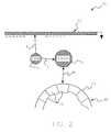
- Fig. 2 The electrical and magnetic forces acting on an exemplary nonmagnetic toner particle T 1 and an exemplary carrier particle C in conventional electrographic printing machine 10 are illustrated in Fig. 2.
- Carrier particle C is alternately attracted to and repulsed from toning roller 20 by magnetic force M 1 .
- the alternating nature or direction of force M 1 is due to the rotation of toning roller 20 and, thus, magnets 26.
- Nonmagnetic toner particle T 1 is attracted to carrier particle C by electrical force E 1 , which is the relatively weak electrostatic force that bonds toner particles to the carrier particles.
- Toner particle T 1 is attracted to support member 16 by force E 2 , i.e., the electrostatic image charge.
- force E 2 When the electrical forces are properly balanced, force E 2 will be sufficiently stronger than force E 1 to cause toner particle T 1 to be stripped from carrier particle C and lodge onto a portion of the electrostatic image charged carried by support member 16.
- the electrical forces are balanced by a development electrode layer (not shown), such as, for example, a layer of nickel, of dielectric support member 16 that is held at ground potential.
- the nonmagnetic toner particle T 1 is not significantly affected by magnetic force M 1 .
- Magnetic force M 1 continues to act on carrier particle C to alternately attract and repulse carrier particle C to and from toning roller 20.
- Electrical force E 1 acts on magnetic toner particle T 2 in a substantially identical manner as it acted on nonmagnetic toner particle T 1 , i.e., tending to bond magnetic toner particle T 2 to carrier particle C.
- Magnetic toner particle T 2 is, however, subjected to magnetic forces that did not significantly affect nonmagnetic toner particle T 1 .
- Magnetic toner particle T 2 is acted upon by magnetic forces M 2 , M 3 , and M 4 . More particularly, magnetic force M 2 exists between toner particle T 2 and carrier particle C, and tends to draw toner particle T 2 toward carrier particle C. Magnetic force M 3 exists between toner particle T 2 and toning roller 20, and tends to draw toner particle T 2 toward toning roller 20. Magnetic force M 4 exists between toner particle T 2 and a second magnetic toner particle T 3 , and tends to draw toner particle T 2 toward toner particle T 3 . None of magnetic forces M 2 , M 3 , and M 4 are directed toward dielectric support member or film 16.
- magnetic force M 3 is generally directed away from dielectric support member or film 16
- magnetic forces M 2 and M 4 are generally directed parallel to dielectric support member or film 16 and in opposing directions.
- magnetic forces M 2 , M 3 and M 4 tend to counteract or reduce the effective electrical force E 2 that attracts magnetic toner particle T 2 to the electrostatic image charge carried by support member 16, and thereby degrade overall image quality.
- Image quality is also degraded due to scavenging of toner particles from the electrostatic image carried on support member 16.
- This scavenging process occurs when a toner particle that has already been deposited on support member 16 is subsequently pulled back off the support member 16 by a subsequent carrier particle that is in close proximity to the toner particle.
- Scavenging is primarily responsible for the variation in the amount of toner deposited from the leading edge to the trailing edge of an image. Only as the image carried by support member 16 emerges from the developer nip area is the toner deposition relatively unaffected by the scavenging process, and thus heavier cross track lines and heavy trailing edges on other image shapes result.
- FIG. 4 one embodiment of an electrographic development or printing machine 30 in accordance with the present invention is shown, and the electrical and magnetic forces acting within electrographic development machine 30 upon an exemplary toner particle having magnetic content T 2 and exemplary carrier particle C are illustrated.
- Electrographic development machine 30 includes, in addition to toning roller 20 and dielectric support member or film 16, a magnetic keeper 34.
- Magnetic keeper 34 such as, for example, a wire or plate, disposed such that film or dielectric support member 16 is between keeper 34 and toner roller 20.
- Magnetic keeper 34 is constructed of a range of materials of varying ferromagnetic strength, such as, for example, a thin wire of slightly magnetic stainless steel having a relatively small amount of ferromagnetic material, such as, for example, 0.04 grams per centimeter of length, for very small ferromagnetic strength/effect to a cold rolled steel plate having a relatively large amount of ferromagnetic material, such as, for example, 16 grams per centimeter of length, for very strong ferromagnetic strength/effect.
- the amount of ferromagnetism and location of magnetic keeper 34 is dependent at least in part upon the desired effect on the toner deposition process.
- the relatively low magnetic reluctance of magnetic keeper 34 tends to draw or attract magnetic toner particle T 2 , thereby counteracting the magnetic forces M 2 , M 3 and M 4 which, as described above, tend to counteract or reduce the effective electrical force E 2 attracting magnetic toner particle T 2 to the electrostatic image charge carried by support member 16.
- magnetic forces M 2 , M 3 , and M 4 act on magnetic toner particle T 2 in a substantially identical manner as described above in regard to electrographic development machine 10, i.e., magnetic forces M 2 , M 3 , and M 4 remain directed generally away from dielectric support member 16 and tend to degrade image quality.
- an additional magnetic force M 5 acts on magnetic toner particle T 2 . More particularly, magnetic force M 5 exists between magnetic toner particle T 2 and magnetic keeper 34, and tends to draw magnetic toner particle T 2 toward keeper 34. Since keeper 34 is disposed between magnetic toner particle T 2 and dielectric support member 16, magnetic force M 5 is directed toward and tends to draw magnetic toner particle T 2 to dielectric support member 16.
- magnetic force M 5 is directed generally opposite to magnetic force M 3 and thereby counteracts or generally balances the magnetic forces acting on magnetic toner particle T 2 within development machine 30. With the magnetic forces generally balanced, the electrical forces acting on toner particle T 2 predominate and the above-described undesirable effects of the magnetic forces on the image are substantially reduced.
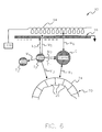
- FIG. 5 a second embodiment of an electrographic development or printing machine 60 in accordance with the present invention is shown, and the electrical and magnetic forces acting within electrographic machine 60 upon an exemplary toner particle having magnetic content T 2 and exemplary carrier particle C are illustrated.
- magnetic keeper 34 acts to straighten or balance magnetic field lines in a passive manner
- the following embodiments of printing machines employ active structures to straighten/balance the magnetic field lines.
- Electrographic development machine 60 includes, in addition to toning roller 20 and dielectric support member or film 16, a rotating magnet 64.
- Rotating magnet 64 is disposed generally opposite toner roller 20, and with dielectric support member 16 disposed between rotating magnet 64 and toner roller 20.
- Rotating magnet 64 includes a plurality of magnets 66 arranged such that the poles thereof are opposite to the poles of magnets 26 of toner roller 20.
- the magnetic forces M 3 and M 5 are directed generally opposite to each other and approximately equal in magnitude.
- the magnetic forces acting on magnetic toner particle T 2 within electrographic development or printing machine 60 are therefore generally balanced, and the electrical forces predominate thereby substantially reducing the above-described undesirable effects of the magnetic forces on the image.
- a magnetic keeper 34 and a rotating magnet 64 are utilized as means for counteracting and generally balancing the magnetic forces acting on the magnetic toner particles within electrographic development machines 30 and 60, respectively.
- the present invention can be alternately configured with various other means for balancing the magnetic forces within the electrographic development machines.
- Such means include various magnetic and/or electromagnetic structures, such as, for example, a wire coil electromagnet.
- electrographic development machine 90 utilizes a wire coil electromagnet 94 as the magnetic/electromagnetic structure to balance the magnetic forces within the development machine.
- Machine 90 also includes controller 100, such as, for example, a microprocessor that actively controls and drives electromagnet 94 to thereby manipulate the magnetic field characteristics on a real-time basis.
- controller 100 such as, for example, a microprocessor that actively controls and drives electromagnet 94 to thereby manipulate the magnetic field characteristics on a real-time basis.
- machine 90 is able to reduce the effects of developer pickup and/or carrier pickup on image quality.
- the magnetic or electromagnetic structure for balancing the magnetic forces within the development machine can range from the relative simplicity of the magnetic keeper 34 of electrographic machine 30 to the moderately complex rotating magnet 64 of machine 60 and beyond to structures that are substantially more complex and/or more powerful.
- the complexity or power required of the magnetic force balancing structure or means depends, at least in part, upon the configuration of particular development machine upon which the balancing structure is to be used including, such as, for example, the diameter or size of the toning roller, the number of magnets therein, and the magnetic forces in the nip area.
Landscapes
- Physics & Mathematics (AREA)
- General Physics & Mathematics (AREA)
- Dry Development In Electrophotography (AREA)
- Magnetic Brush Developing In Electrophotography (AREA)
Applications Claiming Priority (2)
| Application Number | Priority Date | Filing Date | Title |
|---|---|---|---|
| US45386803P | 2003-03-11 | 2003-03-11 | |
| US453868P | 2003-03-11 |
Publications (2)
| Publication Number | Publication Date |
|---|---|
| EP1460488A2 true EP1460488A2 (fr) | 2004-09-22 |
| EP1460488A3 EP1460488A3 (fr) | 2007-04-25 |
Family
ID=32825446
Family Applications (1)
| Application Number | Title | Priority Date | Filing Date |
|---|---|---|---|
| EP04002993A Withdrawn EP1460488A3 (fr) | 2003-03-11 | 2004-02-11 | Procédé et dispositif pour l'impression améliorer avec un révélateur magnétique |
Country Status (2)
| Country | Link |
|---|---|
| US (1) | US20040179867A1 (fr) |
| EP (1) | EP1460488A3 (fr) |
Family Cites Families (21)
| Publication number | Priority date | Publication date | Assignee | Title |
|---|---|---|---|---|
| US3557751A (en) * | 1967-05-20 | 1971-01-26 | Minolta Camera Kk | Device for dry development in electrophotography |
| JPS5581359A (en) * | 1978-12-14 | 1980-06-19 | Ricoh Co Ltd | Electrostatic latent image developing method and device thereof |
| US4357103A (en) * | 1981-03-27 | 1982-11-02 | Eastman Kodak Company | Electrographic apparatus and method featuring compressed-field, magnetic brush development |
| CH659530A5 (fr) * | 1982-11-08 | 1987-01-30 | Eastman Kodak Co | Revelateur electrographique et procede de developpement d'image electrostatique l'utilisant. |
| US4473029A (en) * | 1983-07-01 | 1984-09-25 | Eastman Kodak Company | Electrographic magnetic brush development method, apparatus and system |
| JPS6026378A (ja) * | 1983-07-21 | 1985-02-09 | Nec Kansai Ltd | 現像装置 |
| JPS62135862A (ja) * | 1985-12-10 | 1987-06-18 | Canon Inc | 現像装置 |
| JPH01180580A (ja) * | 1988-01-13 | 1989-07-18 | Nec Corp | 磁気ブラシ現像器 |
| US5080038A (en) * | 1991-06-24 | 1992-01-14 | Eastman Kodak Company | Extended NIP development apparatus having a transport assist magnet |
| US5235385A (en) * | 1992-04-15 | 1993-08-10 | Eastman Kodak Company | Method and apparatus for controlling toner image density |
| US5289242A (en) * | 1992-11-17 | 1994-02-22 | Hewlett-Packard | Method and system for identifying the type of toner print cartridges loaded into electrophotographic printers |
| JPH0867025A (ja) * | 1994-08-23 | 1996-03-12 | Eastman Kodak Co | 電子写真印刷方法及び装置 |
| US5729884A (en) * | 1996-04-29 | 1998-03-24 | Eastman Kodak Company | Method for assembling a print head for an electrographic printer |
| US5732311A (en) * | 1996-12-26 | 1998-03-24 | Eastman Kodak Company | Compliant electrographic recording member and method and apparatus for using same |
| US5818476A (en) * | 1997-03-06 | 1998-10-06 | Eastman Kodak Company | Electrographic printer with angled print head |
| US5889544A (en) * | 1997-04-10 | 1999-03-30 | Eastman Kodak Company | Electrographic printer with multiple transfer electrodes |
| US5956544A (en) * | 1997-11-14 | 1999-09-21 | Eastman Kodak Company | Electrostatographic reproduction apparatus with electrometer control and method of calibrating the electrometer |
| US5926676A (en) * | 1998-01-08 | 1999-07-20 | Xerox Corporation | Apparatus and method for non-interactive magnetic brush development |
| US6610451B2 (en) * | 2000-12-26 | 2003-08-26 | Heidelberger Druckmaschinen Ag | Development systems for magnetic toners having reduced magnetic loadings |
| US6990307B2 (en) * | 2002-07-02 | 2006-01-24 | Eastman Kodak Company | Device for transporting particles |
| US6909856B2 (en) * | 2002-10-01 | 2005-06-21 | Eastman Kodak Company | Functionality switching for MICR printing |
-
2004
- 2004-02-06 US US10/772,870 patent/US20040179867A1/en not_active Abandoned
- 2004-02-11 EP EP04002993A patent/EP1460488A3/fr not_active Withdrawn
Also Published As
| Publication number | Publication date |
|---|---|
| EP1460488A3 (fr) | 2007-04-25 |
| US20040179867A1 (en) | 2004-09-16 |
Similar Documents
| Publication | Publication Date | Title |
|---|---|---|
| US4030447A (en) | Developing device | |
| US5031570A (en) | Printing apparatus and toner/developer delivery system therefor | |
| EP0024110A1 (fr) | Appareil de développement à rouleaux multiples | |
| US4282303A (en) | Development method and apparatus | |
| US6526247B2 (en) | Electrostatic image developing process with optimized setpoints | |
| JPH0321909B2 (fr) | ||
| US4941019A (en) | Apparatus for developing electrostatic latent image | |
| EP1460488A2 (fr) | Procédé et dispositif pour l'impression améliorer avec un révélateur magnétique | |
| JPH11249441A (ja) | ノンインタラクティブ磁気ブラシ現像装置 | |
| CA1142996A (fr) | Methode et dispositif d'enregistrement par voie electrophotographique | |
| US5376997A (en) | Rotating sleeve-type magnetic brush cleaning device | |
| US7031645B2 (en) | Apparatus and method for non-interactive magnetic brush development | |
| US5589917A (en) | Donor rolls with magnetically coupled (Transformer) commutation | |
| US4929981A (en) | Developing apparatus | |
| JP2856342B2 (ja) | 画像形成装置 | |
| JPS5950471A (ja) | 電子写真現像方法及び装置 | |
| JPS5614264A (en) | Developing device | |
| JPH10509662A (ja) | プリンタユニットにおけるトナー粒子の供給方法及び装置 | |
| EP0160503B1 (fr) | Procédé de développement pour électrophotographie | |
| JPS58149076A (ja) | 乾式現像装置 | |
| US5745827A (en) | Bundled steel wire SED communicator secondary cores | |
| JPH0138601Y2 (fr) | ||
| JPH0132505B2 (fr) | ||
| JP2000098709A (ja) | 画像形成装置 | |
| JPS61219072A (ja) | 転写装置 |
Legal Events
| Date | Code | Title | Description |
|---|---|---|---|
| PUAI | Public reference made under article 153(3) epc to a published international application that has entered the european phase |
Free format text: ORIGINAL CODE: 0009012 |
|
| AK | Designated contracting states |
Kind code of ref document: A2 Designated state(s): AT BE BG CH CY CZ DE DK EE ES FI FR GB GR HU IE IT LI LU MC NL PT RO SE SI SK TR |
|
| AX | Request for extension of the european patent |
Extension state: AL LT LV MK |
|
| PUAL | Search report despatched |
Free format text: ORIGINAL CODE: 0009013 |
|
| AK | Designated contracting states |
Kind code of ref document: A3 Designated state(s): AT BE BG CH CY CZ DE DK EE ES FI FR GB GR HU IE IT LI LU MC NL PT RO SE SI SK TR |
|
| AX | Request for extension of the european patent |
Extension state: AL LT LV MK |
|
| 17P | Request for examination filed |
Effective date: 20070928 |
|
| AKX | Designation fees paid |
Designated state(s): AT BE BG CH CY CZ DE DK EE ES FI FR GB GR HU IE IT LI LU MC NL PT RO SE SI SK TR |
|
| STAA | Information on the status of an ep patent application or granted ep patent |
Free format text: STATUS: THE APPLICATION IS DEEMED TO BE WITHDRAWN |
|
| 18D | Application deemed to be withdrawn |
Effective date: 20090829 |