EP1460507A2 - Raumtemperaturregelsystem - Google Patents
Raumtemperaturregelsystem Download PDFInfo
- Publication number
- EP1460507A2 EP1460507A2 EP04002442A EP04002442A EP1460507A2 EP 1460507 A2 EP1460507 A2 EP 1460507A2 EP 04002442 A EP04002442 A EP 04002442A EP 04002442 A EP04002442 A EP 04002442A EP 1460507 A2 EP1460507 A2 EP 1460507A2
- Authority
- EP
- European Patent Office
- Prior art keywords
- control unit
- radiator
- signals
- demand
- room
- Prior art date
- Legal status (The legal status is an assumption and is not a legal conclusion. Google has not performed a legal analysis and makes no representation as to the accuracy of the status listed.)
- Granted
Links
Images
Classifications
-
- F—MECHANICAL ENGINEERING; LIGHTING; HEATING; WEAPONS; BLASTING
- F24—HEATING; RANGES; VENTILATING
- F24D—DOMESTIC- OR SPACE-HEATING SYSTEMS, e.g. CENTRAL HEATING SYSTEMS; DOMESTIC HOT-WATER SUPPLY SYSTEMS; ELEMENTS OR COMPONENTS THEREFOR
- F24D19/00—Details
- F24D19/10—Arrangement or mounting of control or safety devices
- F24D19/1006—Arrangement or mounting of control or safety devices for water heating systems
- F24D19/1009—Arrangement or mounting of control or safety devices for water heating systems for central heating
- F24D19/1015—Arrangement or mounting of control or safety devices for water heating systems for central heating using a valve or valves
- F24D19/1018—Radiator valves
-
- G—PHYSICS
- G05—CONTROLLING; REGULATING
- G05D—SYSTEMS FOR CONTROLLING OR REGULATING NON-ELECTRIC VARIABLES
- G05D23/00—Control of temperature
- G05D23/19—Control of temperature characterised by the use of electric means
- G05D23/1902—Control of temperature characterised by the use of electric means characterised by the use of a variable reference value
- G05D23/1905—Control of temperature characterised by the use of electric means characterised by the use of a variable reference value associated with tele control
Definitions
- the invention relates to a system for controlling the room temperature, preferably in a building with several spatial sections.
- control systems of this type include, for example, a boiler or burner for heating water, which is passed through pipes over radiators in the rooms to be heated.
- control of such a system is often carried out taking into account the room temperature of a single room of the building, and optionally taking into account the outside temperature.
- a central room unit can be provided, via which the entire heating system can be regulated.
- This room unit outputs setpoint signals to the different radiator controllers of the building.
- it supplies a demand information to a control unit for the burner or boiler of the heating systems, which takes into account the temperature in a plurality of rooms.
- the invention has for its object to provide a system for controlling the room temperature, which allows improved control of the room temperature without a correspondingly increased wiring costs.
- the proposed system for controlling the room temperature accordingly comprises a room unit for transmitting setpoint signals, a plurality of heater controllers for receiving the setpoint signals and for transmitting demand signals and a control unit for receiving the demand signals and adjusting the power supply to the system based on the received demand signals , where the room unit is registered with the radiator controllers and the control unit.
- radiator controllers use an identification signal of the room unit when sending their demand information, they can directly address the control unit, although they were never checked in at the control unit or the control unit with them.
- the demand signal also includes information regarding the quantity of the demand as well as a Identification signal of the sending radiator controller. This allows the control unit to more accurately control the power supply to the system.
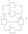
- 1 denotes a room unit
- 2 denotes a radiator controller
- 3 denotes a control unit
- the room unit 1 sends setpoint signals.
- the radiator controllers 2 send demand signals and receive setpoint signals.
- the control unit 3 receives demand signals and adjusts the power supply to a boiler, burner or water heater, not shown in the figure, which heats water supplied to the radiators controlled by the radiators.
- the proposed system uses only radio signals.
- the radio signals used in this case include identification signals and information signals.
- the information of the command value signals is the target value, and the information of the required signals is the demand information.
- the identification signal of the setpoint signal comprises at least the identification number of the room unit.
- the identification signal of the demand signal comprises the identification signal of the room unit and the identification signal of the sending radiator controller.
- This measure eliminates the expense of registering the radiator controller in the control unit.
- the room unit 1 comes with only one transmitting device and the control unit 3 only with a receiving device.
- the information included in the demand signal also includes information regarding the quantity of demand. This is represented by information regarding the degree of opening of the valve of the controlled radiator. For example, each radiator controller 2 sends such a signal repeatedly in fixed or variable time intervals. However, it is also intended a transmission when changing the need.
- This demand signal comprises an identification signal of the room unit 1, as well as an identification signal of the transmitting radiator controller 2.
- the demand signals of all radiator controller 2 are received.
- the control unit 3 makes a selection among the received demand signals, for example by using the four demand signals with the highest demand for further regulation of the energy supply.
- the control unit 3 stores the demand signals of all radiators and the source of these demand signals in order to then use them for further control of the energy supply can.
- the room unit 1 in the radiator controller 2 and the control unit 3 is checked.
- the room unit 1 is first checked at the control unit 3 and then at the radiator controllers 2.
- the Einbuchvorgang When Einbuchvorgang the Einbuchvorgang is first initiated at the radiator controller 2 or the control unit 3, for example by the operation of one or more corresponding keys. Then the booking process is initiated on the room unit 1, for example, again by pressing a special button. In this learning process, the control unit 3 and the radiator controller 2 get to know the identification signal of the room unit 1.
- the system according to the figure is preferably delivered in the form that it comprises a room unit 1, a control unit 3 and three radiator controller 2, wherein the room unit 1 are already factory-registered in the three radiator controls 2 and the control unit 3.
- the measures described above make it easy to add more components to this system.
- the room unit 1 can fulfill additional functions beyond the above-mentioned functions. With the help of a timer, it can, for example, the setpoint specification make weekday and time selective. In addition, it can cause a nighttime lowering in the individual rooms.
- the room unit 1 can perceive further control tasks by means of its own temperature sensor or by means of an interface enable remote control of the control system via a data network.
- the radiator controllers include a temperature sensor beyond the said elements in order to determine the temperature in the vicinity of the radiator and an adjusting device, in which an operator can vary the respective predetermined setpoint.
- control unit may also be equipped such that it carries out a regulation of the energy supply, for example by taking into account the flow temperature.
- This system comprises a room unit for sending setpoint signals, a plurality of heater controllers for receiving the setpoint signals and for transmitting demand signals, and a control unit for receiving the demand signals and adjusting the power supply to the system based on the received demand signals.
- the demand signals sent by the radiator controllers comprise the identification signal of the room unit.
Landscapes
- Engineering & Computer Science (AREA)
- Physics & Mathematics (AREA)
- Thermal Sciences (AREA)
- Chemical & Material Sciences (AREA)
- Combustion & Propulsion (AREA)
- Mechanical Engineering (AREA)
- General Engineering & Computer Science (AREA)
- General Physics & Mathematics (AREA)
- Automation & Control Theory (AREA)
- Steam Or Hot-Water Central Heating Systems (AREA)
- Control Of Temperature (AREA)
Abstract
Description
- Die Erfindung bezieht sich auf ein System zum Regeln der Raumtemperatur, vorzugsweise in einem Gebäude mit mehreren räumlichen Abschnitten.
- Es ist eine Vielzahl von Regelsystemen dieser Art bekannt. Diese umfassen beispielsweise einen Kessel oder Brenner zur Erwärmung von Wasser, das über Rohre über Heizkörper in den zu erwärmenden Räumen geführt wird.
- Die Regelung eines solchen Systems erfolgt dabei häufig unter Berücksichtigung der Raumtemperatur eines einzigen Raumes des Gebäudes, sowie gegebenenfalls unter Berücksichtigung der Außentemperatur.
- Die Qualität der Regelung und damit der Wohnkomfort könnte nun dadurch erhöht werden, dass die Temperatur in einer Mehrzahl von Räumen des Gebäudes berücksichtigt wird. Bei einem solchen System kann ein zentrales Raumgerät vorgesehen sein, über das sich die gesamte Heizungsanlage regeln lässt. Dieses Raumgerät gibt an die unterschiedlichen Heizkörperregler des Gebäudes Sollwertsignale ab. Darüber hinaus führt es einer Steuereinheit für den Brenner oder Kessel der Heizungsanlagen eine Bedarfsinformation zu, die die Temperatur in einer Mehrzahl von Räumen berücksichtigt.
- Systeme dieser Art ziehen jedoch einen erheblichen Verdrahtungsaufwand nach sich, der mit immensen Installationskosten verbunden ist.
- Der Erfindung liegt die Aufgabe zugrunde, ein System zum Regeln der Raumtemperatur anzugeben, das eine verbesserte Regelung der Raumtemperatur ohne einen entsprechend erhöhten Verdrahtungsaufwand ermöglicht.
- Diese Aufgabe wird durch ein System zum Regeln der Raumtemperatur mit den im Patentanspruch 1 angegebenen Mitteln gelöst.
- Das vorgeschlagene System zum Regeln der Raumtemperatur umfasst dementsprechend ein Raumgerät zum Senden von Sollwertsignalen, einer Mehrzahl von Heizkörperreglern zum Empfangen der Sollwertsignale und zum Senden von Bedarfssignalen und einer Steuereinheit zum Empfangen der Bedarfssignale und zum Einstellen der Energiezufuhr zu dem System auf der Grundlage der empfangenen Bedarfssignale, wobei das Raumgerät bei den Heizkörperreglern und der Steuereinheit eingebucht ist.
- Dadurch, dass die Heizkörperregler beim Versenden ihrer Bedarfsinformation ein Identifikationssignal des Raumgerätes verwenden, können diese die Steuereinheit direkt ansprechen, obwohl sie niemals bei der Steuereinheit eingebucht wurden oder die Steuereinheit bei ihnen.
- Durch diese Maßnahme ist das System einfach zu installieren und darüber hinaus auch einfach zu erweitern. Soll ein neuer Heizkörperregler hinzugefügt werden, wird das Raumgerät wiederum lediglich bei dem neuen Heizkörperregler eingebucht. Da er hierbei auch das Identifikationssignal des Raumgerätes kennen lernt, kann er dies dann auch verwenden, um die Steuereinheit direkt anzusprechen. Darüber hinaus führt diese Maßnahme zu einem verringerten Materialaufwand.
- Vorteilhafte Weiterbildungen der Erfindung sind Gegenstand der Unteransprüche.
- Das Bedarfssignal umfasst darüber hinaus auch noch eine Information bezüglich der Quantität des Bedarfes sowie ein Identifikationssignal des sendenden Heizkörperreglers. Dies erlaubt der Steuereinheit eine genauere Regelung der Energiezufuhr zu dem System.
- Ein bevorzugtes Ausführungsbeispiel der Erfindung wird nachfolgend anhand der Figur beschrieben.
- In der Figur 1 ist mit 1 ein Raumgerät, mit 2 ein Heizkörperregler und mit 3 eine Steuereinheit bezeichnet.
- Das Raumgerät 1 sendet Sollwertsignale. Die Heizkörperregler 2 senden Bedarfssignale und empfangen Sollwertsignale. Die Steuereinheit 3 empfängt Bedarfssignale und stellt die Energiezufuhr zu einem in der Figur nicht gezeigten Kessel, Brenner oder Durchlauferhitzer ein, der Wasser erwärmt, das den von den Heizköperreglern geregelten Heizkörpern zugeführt wird.
- Das vorgeschlagene System verwendet ausschließlich Funksignale. Die dabei verwendeten Funksignale umfassen Identifikationssignale und Informationssignale.
- Die Information der Sollwertsignale ist der Sollwert, und die Information der Bedarfssignale ist die Bedarfsinformation.
- Das Identifikationssignal des Sollwertsignals umfasst zumindest die Identifikationsnummer des Raumgerätes. Das Identifikationssignal des Bedarfssignals umfasst das Identifikationssignal des Raumgerätes sowie das Identifikationssignal des sendenden Heizkörperreglers.
- Hierdurch wird es ermöglicht, dass jeder Heizkörperregler 2 die Steuereinheit 3 direkt ansprechen kann.
- Durch diese Maßnahme entfällt Aufwand für das Einbuchen der Heizkörperregler bei der Steuereinheit.
- Darüber hinaus wird durch die gezeigte Vorgehensweise lediglich in den Heizkörperreglern 2 eine Sende- und Empfangseinrichtung benötigt. Dagegen kommt das Raumgerät 1 mit lediglich einer Sendeinrichtung und die Steuereinheit 3 lediglich mit einer Empfangseinrichtung aus.
- Dies verringert den schaltungstechnischen Aufwand und damit die Kosten des Gesamtsystems.
- Die in dem Bedarfssignal enthaltene Information umfasst auch eine Information bezüglich der Quantität des Bedarfs. Diese wird durch eine Information bezüglich des Grades der Öffnung des Ventils des geregelten Heizkörpers repräsentiert. Ein solches Signal sendet jeder Heizkörperregler 2 beispielsweise wiederholt in festen oder variablen Zeitabschnitten. Es ist aber darüber hinaus auch eine Übersendung bei Veränderung des Bedarfs vorgesehen. Dieses Bedarfssignal umfasst ein Identifikationssignal des Raumgerätes 1, sowie auch ein Identifikationssignal des sendenden Heizkörperreglers 2.
- In der Steuereinheit 3 werden die Bedarfssignale aller Heizkörperregler 2 empfangen. Die Steuereinheit 3 trifft unter den empfangenen Bedarfssignalen eine Auswahl, beispielsweise indem sie die vier Bedarfssignale mit dem höchsten Bedarf zur weiteren Regelung der Energiezufuhr heranzieht. Hierzu speichert die Steuereinheit 3 die Bedarfssignale aller Heizkörper sowie die Quelle dieser Bedarfssignale, um sie dann zur weiteren Regelung der Energiezufuhr heranziehen zu können.
- Bei dem gezeigten System ist das Raumgerät 1 bei dem Heizkörperregler 2 sowie bei der Steuereinheit 3 eingebucht. Zu diesem Zweck wird das Raumgerät 1 zunächst bei der Steuereinheit 3 und dann bei den Heizkörperreglern 2 eingebucht.
- Beim Einbuchvorgang wird zunächst der Einbuchvorgang bei dem Heizkörperregler 2 oder der Steuereinheit 3 eingeleitet, beispielsweise durch die Betätigung einer oder mehrerer entsprechender Tasten. Daraufhin wird der Einbuchvorgang am Raumgerät 1 eingeleitet, beispielsweise wiederum durch die Betätigung einer speziellen Taste. Bei diesem Einlernvorgang lernen die Steuereinheit 3 und die Heizkörperregler 2 das Identifikationssignal des Raumgerätes 1 kennen.
- Das System gemäß der Figur wird bevorzugt in der Form ausgeliefert, dass es ein Raumgerät 1, eine Steuereinheit 3 sowie drei Heizkörperregler 2 umfasst, wobei das Raumgerät 1 bereits werksseitig bei den drei Heizkörperreglern 2 sowie bei der Steuereinheit 3 eingebucht sind. Durch die oben beschriebenen Maßnahmen ist es aber leicht, diesem System weitere Komponenten hinzuzufügen.
- Darüber hinaus ist es durch die Verwendung des Identifikationssignals des Raumgerätes 1 durch die Heizkörperregler 2 möglich, dass die Heizkörperregler 2 mit der Steuereinheit 3 kommunizieren, ohne dass diese beiden Geräte beieinander eingebucht werden. Dies vereinfacht den gesamten Einbuchungsvorgang und erleichtert die Erweiterung des Systems. Darüber hinaus spart diese Maßnahme eine Empfangseinrichtung in dem Raumgerät 1.
- Das Raumgerät 1 kann über die oben genannten Funktionen hinaus noch weitere Funktionen erfüllen. Mit Hilfe einer Zeitschaltuhr kann es beispielsweise die Sollwertvorgabe wochentags- und uhrzeitselektiv vornehmen. Darüber hinaus kann es eine Nachtabsenkung in den einzelnen Räumen bewirken.
- Das Raumgerät 1 kann mittels eines eigenen Temperaturfühlers weitere Steuerungsaufgaben wahrnehmen oder mittels einer Schnittstelle eine Fernsteuerung des Regelsystems über ein Datennetz ermöglichen.
- Die Heizkörperregler umfassen über die genannten Elemente hinaus einen Temperaturfühler, um die Temperatur in der Nähe des Heizkörpers zu ermitteln und eine Einstelleinrichtung, bei der eine Bedienperson den jeweils vorgegebenen Sollwert variieren kann.
- Die Steuereinheit kann alternativ zu obiger Darstellungsweise auch derart ausgestattet sein, dass sie eine Regelung der Energiezufuhr durchführt, beispielsweise durch eine Berücksichtigung der Vorlauftemperatur.
- Vorgeschlagen wird ein System zum Regeln der Raumtemperatur in einem Gebäude mittels Heizkörpern. Dieses System weist ein Raumgerät zum Senden von Sollwertsignalen, eine Mehrzahl von Heizkörperreglern zum Empfangen der Sollwertsignale und zum Senden von Bedarfssignalen und eine Steuereinheit auf, die zum Empfangen der Bedarfssignale und zum Einstellen der Energiezufuhr zu dem System auf der Grundlage der empfangenen Bedarfssignale dient. Die von den Heizkörperreglern gesendeten Bedarfssignale umfassen das Identifikationssignal des Raumgerätes. Hierdurch wird eine vereinfachte Kommunikation zwischen den Geräten, eine vereinfachte Installation des Systems sowie ein verringerter Materialaufwand bei der Ausstattung des Systems erreicht.
Claims (11)
- System zum Regeln der Raumtemperatur mit
einer Mehrzahl von Heizkörperreglern (2) zum Empfangen von Sollwertsignalen und zum Senden von Bedarfssignalen,
einer Steuereinheit (3) zum Empfangen der Bedarfssignale und zum Einstellen der Energiezufuhr zu dem System auf der Grundlage der empfangenen Bedarfssignale, und
einem bei den Heizkörperreglern und der Steuereinheit einzubuchenden Raumgerät(1) zum Senden der Sollwertsignale,
wobei die von den Heizkörperreglern gesendeten Bedarfssignale ein Identifikationssignal des Raumgerätes umfassen. - System nach Anspruch 1, dadurch gekennzeichnet, dass die Bedarfssignale eine Information bezüglich der Quantität des Bedarfs sowie ein Identifikationssignal des sendenden Heizkörperreglers umfassen.
- System nach Anspruch 1, dadurch gekennzeichnet, dass das Sollwertsignal das Identifikationssignal des Raumgerätes sowie eine Information bezüglich des einzustellenden Sollwertes umfasst.
- System nach Anspruch 1, dadurch gekennzeichnet, dass beim Einbuchen des Raumgerätes bei der Steuereinheit der Einbuchvorgang zuerst bei der Steuereinheit eingeleitet wird, daraufhin der Einbuchvorgang bei dem Raumgerät eingeleitet wird, daraufhin das Raumgerät sein Identifikationssignal sendet und schließlich die Steuereinheit das empfangene Identifikationssignal speichert.
- System nach Anspruch 1, dadurch gekennzeichnet, dass beim Einbuchen des Raumgerätes bei einem Heizkörperregler der Einbuchvorgang zuerst bei dem Heizkörperregler eingeleitet wird, daraufhin der Einbuchvorgang bei dem Raumgerät eingeleitet wird, daraufhin das Raumgerät sein Identifikationssignal sendet und schließlich der Heizkörperreger die empfangenen Identifikationssignale speichert.
- System nach Anspruch 1, dadurch gekennzeichnet, dass die Heizkörperregler zu vorbestimmten Zeitpunkten, nach einem vorbestimmten Zeitintervall oder nach einer Veränderung des Bedarfs ein Bedarfssignal senden.
- System nach Anspruch 1, dadurch gekennzeichnet, dass die Steuereinheit die Energiezufuhr zu dem System anhand ausgewählter Bedarfsinformationen einstellt.
- System nach Anspruch 1, dadurch gekennzeichnet, dass das System eine Steuereinheit, drei Heizkörperregler und ein bei der Steuereinheit und den Heizkörperreglern eingebuchtes Raumgerät umfasst.
- Raumgerät für ein System nach einem der vorhergehenden Ansprüche.
- Steuereinheit für ein System nach einem der vorhergehenden Ansprüche.
- Heizkörperregler für ein System nach einem der vorhergehenden Ansprüche.
Applications Claiming Priority (2)
| Application Number | Priority Date | Filing Date | Title |
|---|---|---|---|
| DE10312668 | 2003-03-21 | ||
| DE10312668A DE10312668B3 (de) | 2003-03-21 | 2003-03-21 | Raumtemperaturregelsystem |
Publications (3)
| Publication Number | Publication Date |
|---|---|
| EP1460507A2 true EP1460507A2 (de) | 2004-09-22 |
| EP1460507A3 EP1460507A3 (de) | 2005-06-15 |
| EP1460507B1 EP1460507B1 (de) | 2016-12-07 |
Family
ID=32336656
Family Applications (1)
| Application Number | Title | Priority Date | Filing Date |
|---|---|---|---|
| EP04002442.4A Expired - Lifetime EP1460507B1 (de) | 2003-03-21 | 2004-03-01 | Raumtemperaturregelsystem |
Country Status (2)
| Country | Link |
|---|---|
| EP (1) | EP1460507B1 (de) |
| DE (1) | DE10312668B3 (de) |
Cited By (9)
| Publication number | Priority date | Publication date | Assignee | Title |
|---|---|---|---|---|
| GB2462143A (en) * | 2008-07-30 | 2010-02-03 | Ethos Systems Ltd | Heating system comprising wireless radiator control |
| US8182233B2 (en) | 2007-07-13 | 2012-05-22 | Rolls-Royce Plc | Component with a damping filler |
| US8241004B2 (en) | 2008-05-15 | 2012-08-14 | Rolls-Royce, Plc | Component structure |
| US8365388B2 (en) | 2009-01-28 | 2013-02-05 | Rolls-Royce Plc | Method of joining plates of material to form a structure |
| US8529720B2 (en) | 2008-07-24 | 2013-09-10 | Rolls-Royce, Plc | Aerofoil sub-assembly, an aerofoil and a method of making an aerofoil |
| US8701286B2 (en) | 2010-06-02 | 2014-04-22 | Rolls-Royce Plc | Rotationally balancing a rotating part |
| US8920893B2 (en) | 2009-01-27 | 2014-12-30 | Rolls-Royce Plc | Article with an internal structure |
| US8986490B2 (en) | 2010-11-26 | 2015-03-24 | Rolls-Royce Plc | Method of manufacturing a component |
| US9022299B2 (en) | 2007-04-13 | 2015-05-05 | Basic Device Limited | Radiators |
Family Cites Families (6)
| Publication number | Priority date | Publication date | Assignee | Title |
|---|---|---|---|---|
| GB2173920B (en) * | 1985-04-17 | 1989-06-28 | John David Statham | Improvements in and relating to heating systems |
| GB2202058A (en) * | 1987-03-07 | 1988-09-14 | Cambridge Instr Ltd | Temperature control systems |
| DE4221094C2 (de) * | 1992-06-26 | 1997-08-07 | Buderus Heiztechnik Gmbh | Verfahren zur Raumtemperaturregelung |
| DE19710645A1 (de) * | 1997-03-14 | 1998-09-24 | Bosch Gmbh Robert | Anordnung und Verfahren zur Anpassung der Leistung eines Heizgerätes |
| NL1006716C2 (nl) * | 1997-08-04 | 1999-02-08 | Gerd Kurt Nossing | Regelsysteem voor een centrale verwarmingsinstallatie alsmede centrale verwarmingsinstallatie voorzien van een dergelijk regelsysteem. |
| GB2387669B (en) * | 2002-04-16 | 2006-04-26 | Honeywell Control Syst | Improvements in temperature control systems |
-
2003
- 2003-03-21 DE DE10312668A patent/DE10312668B3/de not_active Expired - Lifetime
-
2004
- 2004-03-01 EP EP04002442.4A patent/EP1460507B1/de not_active Expired - Lifetime
Cited By (12)
| Publication number | Priority date | Publication date | Assignee | Title |
|---|---|---|---|---|
| US9022299B2 (en) | 2007-04-13 | 2015-05-05 | Basic Device Limited | Radiators |
| US8182233B2 (en) | 2007-07-13 | 2012-05-22 | Rolls-Royce Plc | Component with a damping filler |
| US8381398B2 (en) | 2007-07-13 | 2013-02-26 | Rolls-Royce Plc | Component with a damping filler and method |
| US8857054B2 (en) | 2007-07-13 | 2014-10-14 | Rolls-Royce Plc | Method of forming an aerofoil with a damping filler |
| US8241004B2 (en) | 2008-05-15 | 2012-08-14 | Rolls-Royce, Plc | Component structure |
| US8529720B2 (en) | 2008-07-24 | 2013-09-10 | Rolls-Royce, Plc | Aerofoil sub-assembly, an aerofoil and a method of making an aerofoil |
| GB2462143A (en) * | 2008-07-30 | 2010-02-03 | Ethos Systems Ltd | Heating system comprising wireless radiator control |
| GB2462143B (en) * | 2008-07-30 | 2013-03-13 | Advanced Design Innovations Uk Ltd | Heating system |
| US8920893B2 (en) | 2009-01-27 | 2014-12-30 | Rolls-Royce Plc | Article with an internal structure |
| US8365388B2 (en) | 2009-01-28 | 2013-02-05 | Rolls-Royce Plc | Method of joining plates of material to form a structure |
| US8701286B2 (en) | 2010-06-02 | 2014-04-22 | Rolls-Royce Plc | Rotationally balancing a rotating part |
| US8986490B2 (en) | 2010-11-26 | 2015-03-24 | Rolls-Royce Plc | Method of manufacturing a component |
Also Published As
| Publication number | Publication date |
|---|---|
| DE10312668B3 (de) | 2004-06-24 |
| EP1460507B1 (de) | 2016-12-07 |
| EP1460507A3 (de) | 2005-06-15 |
Similar Documents
| Publication | Publication Date | Title |
|---|---|---|
| DE69206825T2 (de) | Verfahren und vorrichtung zur überwachung des zustandes in einem raum | |
| DE69207210T2 (de) | Kommunikationsthermostat | |
| EP2151578B1 (de) | Umwälzpumpenaggregat | |
| DE974945T1 (de) | Universales Fernbedienungsystem und Verfahren mit Gerätaktivierter Einstellung | |
| EP1460507B1 (de) | Raumtemperaturregelsystem | |
| DE102009001224B4 (de) | System zur zentralen Regelung von Betriebseinrichtungen | |
| EP1129599B1 (de) | Verfahren zum betreiben von sende- und empfangseinrichtungen in einem leitsystem für einen oder mehrere räume eines gebäudes | |
| EP3584504B1 (de) | Heizungssystem zur kopplung einer einzelraumregelung mit einem heizgerät | |
| EP1783365A2 (de) | Verfahren zum Übertragen von Daten an eine Windenergieanlage und Windenergieanlage mit geigneter Auswerteeinrichtung | |
| DE202009002866U1 (de) | System zur zentralen Regelung von Heizeinrichtungen | |
| EP0805311A2 (de) | Regelungseinrichtung für eine Heizungsanlage | |
| DE19710853B4 (de) | Heizungsanlage | |
| DE202018001101U1 (de) | Perfektionierte Satellitengruppe der Wasserversorgung | |
| DE102023103643A1 (de) | Vorrichtung für ein Heizsystem sowie Heizsystem und Verfahren zu dessen Betrieb | |
| EP3709122B1 (de) | Vorrichtung zur temperaturregelung von räumen in einem gebäude und verfahren zur temperaturregelung | |
| EP1037124B1 (de) | Vorrichtung zur Steuerung beliebiger Funktionseinrichtungen im Haus | |
| DE102020114319A1 (de) | Steuersystem und ein Verfahren zum Abgleichen einer Heizungsanlage | |
| DE102016223726A1 (de) | Beheizungsanlage eines Gebäudes und Verfahren zum Betreiben der Anlage | |
| EP4027211A1 (de) | Verfahren zum optimieren einer heizkurve und heizungssystem | |
| EP4016237B1 (de) | Regelvorrichtung, system und verfahren zum regeln einer temperatur in einem raum und heizkörpervorrichtung | |
| EP3453979B1 (de) | Verfahren zur zuordnung eines dezentralen geräts eines regelungssystems zur verteilung der heiz- und/oder kühlleistung eines heiz- und/oder kühlsystems zu einem regelkanal einer zentralen regeleinheit | |
| EP2570743A1 (de) | Verfahren zur Zuordnung eines Kommunikationsweges zwischen zwei Komponenten eines klima- und raumlufttechnischen Anlagesystems zu einer, insbesondere erst noch zu bildenden, Kommunikationsgruppe | |
| EP3709121B1 (de) | Regelklemmleiste zur regelung von heiz- oder kühleinrichtungen in gebäuden | |
| DE102014210153B4 (de) | Verfahren zum Betrieb eines Steuergeräts einer Heizungsanlage | |
| EP1750187B1 (de) | Regelungstechnische Einrichtung |
Legal Events
| Date | Code | Title | Description |
|---|---|---|---|
| PUAI | Public reference made under article 153(3) epc to a published international application that has entered the european phase |
Free format text: ORIGINAL CODE: 0009012 |
|
| AK | Designated contracting states |
Kind code of ref document: A2 Designated state(s): AT BE BG CH CY CZ DE DK EE ES FI FR GB GR HU IE IT LI LU MC NL PT RO SE SI SK TR |
|
| AX | Request for extension of the european patent |
Extension state: AL LT LV MK |
|
| PUAL | Search report despatched |
Free format text: ORIGINAL CODE: 0009013 |
|
| AK | Designated contracting states |
Kind code of ref document: A3 Designated state(s): AT BE BG CH CY CZ DE DK EE ES FI FR GB GR HU IE IT LI LU MC NL PT RO SE SI SK TR |
|
| AX | Request for extension of the european patent |
Extension state: AL LT LV MK |
|
| 17P | Request for examination filed |
Effective date: 20051201 |
|
| AKX | Designation fees paid |
Designated state(s): AT BE BG CH CY CZ DE DK EE ES FI FR GB GR HU IE IT LI LU MC NL PT RO SE SI SK TR |
|
| GRAP | Despatch of communication of intention to grant a patent |
Free format text: ORIGINAL CODE: EPIDOSNIGR1 |
|
| RIC1 | Information provided on ipc code assigned before grant |
Ipc: G05D 23/19 20060101AFI20160526BHEP Ipc: F24D 19/10 20060101ALI20160526BHEP |
|
| INTG | Intention to grant announced |
Effective date: 20160622 |
|
| GRAS | Grant fee paid |
Free format text: ORIGINAL CODE: EPIDOSNIGR3 |
|
| GRAA | (expected) grant |
Free format text: ORIGINAL CODE: 0009210 |
|
| AK | Designated contracting states |
Kind code of ref document: B1 Designated state(s): AT BE BG CH CY CZ DE DK EE ES FI FR GB GR HU IE IT LI LU MC NL PT RO SE SI SK TR |
|
| REG | Reference to a national code |
Ref country code: DE Ref legal event code: R081 Ref document number: 502004015403 Country of ref document: DE Owner name: PITTWAY 3 GMBH, CH Free format text: FORMER OWNER: HONEYWELL AG HOME AND BUILDING CONTROL, 71101 SCHOENAICH, DE Ref country code: GB Ref legal event code: FG4D Free format text: NOT ENGLISH |
|
| REG | Reference to a national code |
Ref country code: CH Ref legal event code: EP Ref country code: AT Ref legal event code: REF Ref document number: 852262 Country of ref document: AT Kind code of ref document: T Effective date: 20161215 |
|
| REG | Reference to a national code |
Ref country code: IE Ref legal event code: FG4D Free format text: LANGUAGE OF EP DOCUMENT: GERMAN |
|
| REG | Reference to a national code |
Ref country code: DE Ref legal event code: R096 Ref document number: 502004015403 Country of ref document: DE |
|
| REG | Reference to a national code |
Ref country code: NL Ref legal event code: MP Effective date: 20161207 |
|
| PG25 | Lapsed in a contracting state [announced via postgrant information from national office to epo] |
Ref country code: GR Free format text: LAPSE BECAUSE OF FAILURE TO SUBMIT A TRANSLATION OF THE DESCRIPTION OR TO PAY THE FEE WITHIN THE PRESCRIBED TIME-LIMIT Effective date: 20170308 Ref country code: SE Free format text: LAPSE BECAUSE OF FAILURE TO SUBMIT A TRANSLATION OF THE DESCRIPTION OR TO PAY THE FEE WITHIN THE PRESCRIBED TIME-LIMIT Effective date: 20161207 |
|
| REG | Reference to a national code |
Ref country code: FR Ref legal event code: PLFP Year of fee payment: 14 |
|
| PG25 | Lapsed in a contracting state [announced via postgrant information from national office to epo] |
Ref country code: ES Free format text: LAPSE BECAUSE OF FAILURE TO SUBMIT A TRANSLATION OF THE DESCRIPTION OR TO PAY THE FEE WITHIN THE PRESCRIBED TIME-LIMIT Effective date: 20161207 Ref country code: FI Free format text: LAPSE BECAUSE OF FAILURE TO SUBMIT A TRANSLATION OF THE DESCRIPTION OR TO PAY THE FEE WITHIN THE PRESCRIBED TIME-LIMIT Effective date: 20161207 |
|
| PG25 | Lapsed in a contracting state [announced via postgrant information from national office to epo] |
Ref country code: NL Free format text: LAPSE BECAUSE OF FAILURE TO SUBMIT A TRANSLATION OF THE DESCRIPTION OR TO PAY THE FEE WITHIN THE PRESCRIBED TIME-LIMIT Effective date: 20161207 |
|
| PG25 | Lapsed in a contracting state [announced via postgrant information from national office to epo] |
Ref country code: EE Free format text: LAPSE BECAUSE OF FAILURE TO SUBMIT A TRANSLATION OF THE DESCRIPTION OR TO PAY THE FEE WITHIN THE PRESCRIBED TIME-LIMIT Effective date: 20161207 Ref country code: CZ Free format text: LAPSE BECAUSE OF FAILURE TO SUBMIT A TRANSLATION OF THE DESCRIPTION OR TO PAY THE FEE WITHIN THE PRESCRIBED TIME-LIMIT Effective date: 20161207 Ref country code: RO Free format text: LAPSE BECAUSE OF FAILURE TO SUBMIT A TRANSLATION OF THE DESCRIPTION OR TO PAY THE FEE WITHIN THE PRESCRIBED TIME-LIMIT Effective date: 20161207 Ref country code: SK Free format text: LAPSE BECAUSE OF FAILURE TO SUBMIT A TRANSLATION OF THE DESCRIPTION OR TO PAY THE FEE WITHIN THE PRESCRIBED TIME-LIMIT Effective date: 20161207 |
|
| PG25 | Lapsed in a contracting state [announced via postgrant information from national office to epo] |
Ref country code: BG Free format text: LAPSE BECAUSE OF FAILURE TO SUBMIT A TRANSLATION OF THE DESCRIPTION OR TO PAY THE FEE WITHIN THE PRESCRIBED TIME-LIMIT Effective date: 20170307 Ref country code: PT Free format text: LAPSE BECAUSE OF FAILURE TO SUBMIT A TRANSLATION OF THE DESCRIPTION OR TO PAY THE FEE WITHIN THE PRESCRIBED TIME-LIMIT Effective date: 20170407 Ref country code: IT Free format text: LAPSE BECAUSE OF FAILURE TO SUBMIT A TRANSLATION OF THE DESCRIPTION OR TO PAY THE FEE WITHIN THE PRESCRIBED TIME-LIMIT Effective date: 20161207 |
|
| REG | Reference to a national code |
Ref country code: DE Ref legal event code: R097 Ref document number: 502004015403 Country of ref document: DE |
|
| PLBE | No opposition filed within time limit |
Free format text: ORIGINAL CODE: 0009261 |
|
| STAA | Information on the status of an ep patent application or granted ep patent |
Free format text: STATUS: NO OPPOSITION FILED WITHIN TIME LIMIT |
|
| 26N | No opposition filed |
Effective date: 20170908 |
|
| PG25 | Lapsed in a contracting state [announced via postgrant information from national office to epo] |
Ref country code: SI Free format text: LAPSE BECAUSE OF FAILURE TO SUBMIT A TRANSLATION OF THE DESCRIPTION OR TO PAY THE FEE WITHIN THE PRESCRIBED TIME-LIMIT Effective date: 20161207 Ref country code: DK Free format text: LAPSE BECAUSE OF FAILURE TO SUBMIT A TRANSLATION OF THE DESCRIPTION OR TO PAY THE FEE WITHIN THE PRESCRIBED TIME-LIMIT Effective date: 20161207 Ref country code: MC Free format text: LAPSE BECAUSE OF FAILURE TO SUBMIT A TRANSLATION OF THE DESCRIPTION OR TO PAY THE FEE WITHIN THE PRESCRIBED TIME-LIMIT Effective date: 20161207 |
|
| REG | Reference to a national code |
Ref country code: IE Ref legal event code: MM4A |
|
| PG25 | Lapsed in a contracting state [announced via postgrant information from national office to epo] |
Ref country code: LU Free format text: LAPSE BECAUSE OF NON-PAYMENT OF DUE FEES Effective date: 20170301 |
|
| PG25 | Lapsed in a contracting state [announced via postgrant information from national office to epo] |
Ref country code: IE Free format text: LAPSE BECAUSE OF NON-PAYMENT OF DUE FEES Effective date: 20170301 |
|
| REG | Reference to a national code |
Ref country code: BE Ref legal event code: MM Effective date: 20170331 |
|
| REG | Reference to a national code |
Ref country code: FR Ref legal event code: PLFP Year of fee payment: 15 |
|
| PG25 | Lapsed in a contracting state [announced via postgrant information from national office to epo] |
Ref country code: BE Free format text: LAPSE BECAUSE OF NON-PAYMENT OF DUE FEES Effective date: 20170331 |
|
| PG25 | Lapsed in a contracting state [announced via postgrant information from national office to epo] |
Ref country code: HU Free format text: LAPSE BECAUSE OF FAILURE TO SUBMIT A TRANSLATION OF THE DESCRIPTION OR TO PAY THE FEE WITHIN THE PRESCRIBED TIME-LIMIT; INVALID AB INITIO Effective date: 20040301 |
|
| PG25 | Lapsed in a contracting state [announced via postgrant information from national office to epo] |
Ref country code: CY Free format text: LAPSE BECAUSE OF NON-PAYMENT OF DUE FEES Effective date: 20161207 |
|
| PG25 | Lapsed in a contracting state [announced via postgrant information from national office to epo] |
Ref country code: TR Free format text: LAPSE BECAUSE OF FAILURE TO SUBMIT A TRANSLATION OF THE DESCRIPTION OR TO PAY THE FEE WITHIN THE PRESCRIBED TIME-LIMIT Effective date: 20161207 |
|
| REG | Reference to a national code |
Ref country code: DE Ref legal event code: R081 Ref document number: 502004015403 Country of ref document: DE Owner name: PITTWAY 3 GMBH, CH Free format text: FORMER OWNER: HONEYWELL AG, HOME AND BUILDING CONTROL, 71101 SCHOENAICH, DE |
|
| REG | Reference to a national code |
Ref country code: GB Ref legal event code: 732E Free format text: REGISTERED BETWEEN 20211014 AND 20211020 |
|
| REG | Reference to a national code |
Ref country code: AT Ref legal event code: PC Ref document number: 852262 Country of ref document: AT Kind code of ref document: T Owner name: PITTWAY 3 GMBH, CH Effective date: 20220126 |
|
| PGFP | Annual fee paid to national office [announced via postgrant information from national office to epo] |
Ref country code: FR Payment date: 20230323 Year of fee payment: 20 Ref country code: AT Payment date: 20230320 Year of fee payment: 20 |
|
| PGFP | Annual fee paid to national office [announced via postgrant information from national office to epo] |
Ref country code: GB Payment date: 20230321 Year of fee payment: 20 |
|
| P01 | Opt-out of the competence of the unified patent court (upc) registered |
Effective date: 20230601 |
|
| PGFP | Annual fee paid to national office [announced via postgrant information from national office to epo] |
Ref country code: DE Payment date: 20230427 Year of fee payment: 20 Ref country code: CH Payment date: 20230402 Year of fee payment: 20 |
|
| REG | Reference to a national code |
Ref country code: DE Ref legal event code: R071 Ref document number: 502004015403 Country of ref document: DE |
|
| REG | Reference to a national code |
Ref country code: CH Ref legal event code: PL |
|
| REG | Reference to a national code |
Ref country code: GB Ref legal event code: PE20 Expiry date: 20240229 |
|
| REG | Reference to a national code |
Ref country code: AT Ref legal event code: MK07 Ref document number: 852262 Country of ref document: AT Kind code of ref document: T Effective date: 20240301 |
|
| PG25 | Lapsed in a contracting state [announced via postgrant information from national office to epo] |
Ref country code: GB Free format text: LAPSE BECAUSE OF EXPIRATION OF PROTECTION Effective date: 20240229 |