EP1460968B1 - Dispositif detachable dote d'un element de sensibilite electrique - Google Patents
Dispositif detachable dote d'un element de sensibilite electrique Download PDFInfo
- Publication number
- EP1460968B1 EP1460968B1 EP02805603A EP02805603A EP1460968B1 EP 1460968 B1 EP1460968 B1 EP 1460968B1 EP 02805603 A EP02805603 A EP 02805603A EP 02805603 A EP02805603 A EP 02805603A EP 1460968 B1 EP1460968 B1 EP 1460968B1
- Authority
- EP
- European Patent Office
- Prior art keywords
- assembly
- detachable
- thermo
- detachable device
- joint
- Prior art date
- Legal status (The legal status is an assumption and is not a legal conclusion. Google has not performed a legal analysis and makes no representation as to the accuracy of the status listed.)
- Expired - Lifetime
Links
Images


Classifications
-
- A—HUMAN NECESSITIES
- A61—MEDICAL OR VETERINARY SCIENCE; HYGIENE
- A61B—DIAGNOSIS; SURGERY; IDENTIFICATION
- A61B17/00—Surgical instruments, devices or methods
- A61B17/12—Surgical instruments, devices or methods for ligaturing or otherwise compressing tubular parts of the body, e.g. blood vessels or umbilical cord
- A61B17/12022—Occluding by internal devices, e.g. balloons or releasable wires
-
- A—HUMAN NECESSITIES
- A61—MEDICAL OR VETERINARY SCIENCE; HYGIENE
- A61B—DIAGNOSIS; SURGERY; IDENTIFICATION
- A61B17/00—Surgical instruments, devices or methods
- A61B17/12—Surgical instruments, devices or methods for ligaturing or otherwise compressing tubular parts of the body, e.g. blood vessels or umbilical cord
- A61B17/12022—Occluding by internal devices, e.g. balloons or releasable wires
- A61B17/12099—Occluding by internal devices, e.g. balloons or releasable wires characterised by the location of the occluder
- A61B17/12109—Occluding by internal devices, e.g. balloons or releasable wires characterised by the location of the occluder in a blood vessel
- A61B17/12113—Occluding by internal devices, e.g. balloons or releasable wires characterised by the location of the occluder in a blood vessel within an aneurysm
-
- A—HUMAN NECESSITIES
- A61—MEDICAL OR VETERINARY SCIENCE; HYGIENE
- A61B—DIAGNOSIS; SURGERY; IDENTIFICATION
- A61B17/00—Surgical instruments, devices or methods
- A61B17/12—Surgical instruments, devices or methods for ligaturing or otherwise compressing tubular parts of the body, e.g. blood vessels or umbilical cord
- A61B17/12022—Occluding by internal devices, e.g. balloons or releasable wires
- A61B17/12131—Occluding by internal devices, e.g. balloons or releasable wires characterised by the type of occluding device
- A61B17/12168—Occluding by internal devices, e.g. balloons or releasable wires characterised by the type of occluding device having a mesh structure
- A61B17/12172—Occluding by internal devices, e.g. balloons or releasable wires characterised by the type of occluding device having a mesh structure having a pre-set deployed three-dimensional shape
-
- A—HUMAN NECESSITIES
- A61—MEDICAL OR VETERINARY SCIENCE; HYGIENE
- A61B—DIAGNOSIS; SURGERY; IDENTIFICATION
- A61B17/00—Surgical instruments, devices or methods
- A61B17/12—Surgical instruments, devices or methods for ligaturing or otherwise compressing tubular parts of the body, e.g. blood vessels or umbilical cord
- A61B17/12022—Occluding by internal devices, e.g. balloons or releasable wires
- A61B2017/1205—Introduction devices
-
- A—HUMAN NECESSITIES
- A61—MEDICAL OR VETERINARY SCIENCE; HYGIENE
- A61B—DIAGNOSIS; SURGERY; IDENTIFICATION
- A61B17/00—Surgical instruments, devices or methods
- A61B17/12—Surgical instruments, devices or methods for ligaturing or otherwise compressing tubular parts of the body, e.g. blood vessels or umbilical cord
- A61B17/12022—Occluding by internal devices, e.g. balloons or releasable wires
- A61B2017/1205—Introduction devices
- A61B2017/12054—Details concerning the detachment of the occluding device from the introduction device
- A61B2017/12063—Details concerning the detachment of the occluding device from the introduction device electrolytically detachable
Definitions
- the invention relates generally to a detachable device including a thermo-resistive element, in particular, to an electrolytically or mechanically detachable endovascular device.
- the brain is composed of living cells that require a blood supply to provide oxygen and nutrients.
- a hemorrhage in a blood vessel in the brain or in the space closely surrounding the brain is a common cause of strokes. Hemorrhage refers to bleeding into the brain, usually because of a problem with a blood vessel, for example, an aneurysm.
- An aneurysm is an abnormal bulging and/or weakening of a blood vessel wall.
- the wall may smoothly bulge outwardly in all directions (a fusiform aneurysm) or it may form a sack arising from one wall (a saccular aneurysm). If the aneurysm ruptures, a hemorrhage occurs. This can compress and irritate the surrounding blood vessels, resulting in a reduced supply of oxygen and nutrients to the cells, possibly causing a stroke.
- Aneurysms can be treated from outside the blood vessel using surgical techniques or from inside the blood vessel using endovascular techniques. Endovascular treatment of an aneurysm is performed using a catheter. X-ray, magnetic resonance imaging (MRI) equipment, or other visualization equipment may be used to view the progress during a procedure.
- MRI magnetic resonance imaging
- Electrolytically detachable embolic devices have been proposed to fill aneurysms.
- a core wire or catheter may be used to introduce an embolic coil into an aneurysm.
- the embolic coil may be attached to the distal end of the core wire by an electrolytic sacrificial joint. Once the embolic coil is located in the targeted aneurysm, the coil may be detached from the core wire and deployed in the aneurysm by running an electric current through the electrolytic sacrificial joint.
- a thrombus may form in the aneurysm and, shortly thereafter, complemented with a collagenous material that significantly lessens the potential of the aneurysm rupturing.
- embolic devices may utilize shape-memory polymers or metals, polymer-coated coils fused together by heat, or other thermo-sensitive materials for thermally controlled expansion of the embolic devices in aneurysms.
- Warm saline injections may be used to deliver localized heat to these devices, but this method of heat delivery may be difficult to reproduce in a controllable manner.
- Further impediments to this concept may include differential mixing of saline with blood due to dissimilar thermodynamics, non-uniform heat distribution, heat transfer out of the catheter, and/or physician compliance in maintaining reasonable saline temperature and injection rates.
- the invention involves a detachable thermo-sensitive embolic device that utilizes thermo-resistive heating to cause more uniform heating of the embolic device and more consistent performance than using warm saline to control heating of an embolic device.
- This allows electrical heating of the detachable thermo-sensitive embolic device to expand the device in an aneurysm for embolization.
- the embolic device is connected to a delivery device by a detachable joint, thereby enabling the embolic device to be deployed within a target treatment region within a patient, e.g., within an aneurysm.
- the detachable joint may be an electrolytically erodible joint, allowing electrical heating to electrolytically detach the device to deploy the device into the aneurysm.
- the detachable joint may include one or more mechanical connectors to detachably connect the embolic device to the delivery device.
- the device receives a first current to activate the electrically responsive element. If the device includes an electrolytically erodible joint, a second current may be used to electrolytically detach and deploy the device. Alternatively, other detachable joints may be used.
- the electrically responsive element includes a thermo-resistive element or an expandable thermo-resistive element.
- a preferred aspect of the present invention involves a detachable endovascular device assembly for embolizing an aneurysm.
- the assembly includes a delivery member to deliver the assembly to the aneurysm for embolization, a detachable endovascular device including a thermo-resistive element to deliver heat to the device with passage of a first electrical current through the thermo-resistive element and the device adapted to take a predetermined shape as a result of the heating, and a detachable joint for separating the device from the delivery member.
- the joint may be an electrolytic sacrificial joint joining the device and the delivery member that may separate when a second electrical current is delivered therethrough to deploy the device into the aneurysm for embolization.
- the joint may be a mechanical or interference fit joint that may be released by mechanically moving one element of the joint or by applying a force to the joint, e.g., using fluid pressure.
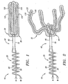
- an endovascular device assembly 10 that includes a delivery member 20 and a detachable, thermo-resistive, expandable, embolic device 30.
- the embolic device 30 is joined to the delivery member 20 by an electrolytic sacrificial joint 40.
- the device assembly 10 may be used for embolizing an aneurysm, although the device assembly 10 may also be adaptable for treating other conditions, such as endovascular occlusions in arteries, veins, vascular malformations, and arteriovenous fistulas.
- the device assembly 10 may also be used for forming an occlusion in other areas of a mammalian body, or for other purposes or applications.
- the delivery member 20 includes an insulated, conductive pusher wire 50 helically wrapped with an insulated, conductive return wire 60.
- the delivery member 20 may include a catheter (not shown) with delivery and return wires carried by the catheter.
- a delivery wire may be located along a longitudinal axis of the catheter and a return wire may be located in an outer sheath of the catheter.
- the electrolytic sacrificial joint 40 is preferably similar to the electrolytic sacrificial joint of the Guglielmi Detachable Coil (GDC) manufactured by Boston Scientific/Target of Fremont, California. Further, the assembly 10 could be powered by current generated from a standard Guglielmi Detachable Coil (GDC) power supply made by Boston Scientific/Target using a simple reusable electronic plug-in coupling.
- GDC Guglielmi Detachable Coil
- the electrolytic sacrificial joint 40 includes a bare conductive portion or detachment wire 70 of the push wire 50 and a bare conductive portion or detachment wire 80 of the return wire 60.
- the detachment wires 70, 80 form the sacrificial joint or corrosion junctions 40.
- the detachable, thermo-resistive, expandable, embolic device 30 may include an insulated hub 90 where the electrolytic sacrificial joint 40 joins the detachable device 30.
- the detachable device 30 may include multiple appendages 100 extending from the hub 90.
- Each appendage 100 may include a platinum-tungsten (PtW) alloy wire or thin film loop 110.
- PtW platinum-tungsten
- the wire or thin film loops 110 may be made of other materials, such as silver, silver-chloride, copper, platinum, chromium, aluminum, titanium, and nickel either in their pure form or as a combination thereof.
- Thin films can be applied to the device 30 by, for example, adhering cut sheet constructs of the films to the device 30, or by selectively masking the device 30 and vapor-depositing or sputter coating the conducting material onto the device 30.
- the wire or thin film loops 110 are also radio-opaque to allow for radiographic visualization.
- each wire loop 110 may be attached to the push wire 70 and a second, opposite end of each wire loop 110 may be attached to the return wire 80.
- the wire loops 110 form thermo-resistive heating elements that heat up with the passage of electrical current therethrough.
- the wire loops 110 may be encased in a thermo-sensitive, shape memory polymer 120 that expands ( FIG. 2 ) when heated by the wire loops 110.
- the detachable device 30 expands to a shape having a larger diameter or other cross-section than that before application of current/heat.
- Other thermo-sensitive materials may be used to cause the device 30 to expand when heated by electrical current.
- polymer-coated, pre-shaped memory coils may be fused together, and, upon application of heat, the polymer becomes flowable, allowing the pre-shaped memory coils to take their natural expanded shape.
- the detachable embolic device 30 may include other numbers of elements 110 (e.g., 1,2, 3, 5, 6, etc.).
- the endovascular device assembly 10 is delivered to a target aneurysm site via the delivery member 20, by insertion through the lumen of a micro-catheter, the distal end of the micro-catheter having been previously positioned at the aneurysm site.
- the detachable, thermo-resistive, expandable, embolic device 30 may be introduced into the aneurysm.
- the detachable embolic device 30 is electrically actuated and thermally expanded by supplying a first current through the thermo-resistive coils 110 of the detachable embolic device 30.
- the first current may pass through the push wire 50 and the exposed conductive wire 70, through the thermo-resistive coils 110, and returns through the exposed conductive wire 80 and the return wire 60.
- Electrical current through the thermo-resistive wire loops 110 causes the loops 110 and, hence, the thermo-sensitive shape memory polymer to be heated.
- the thermo-sensitive shape memory polymer expands into a configuration, such as that shown in FIG. 2 , causing it to be retained within the aneurysm.
- the detachable embolic device 30 is shown as having a hand-like configuration, the detachable embolic device 30 may have any expanded configuration.
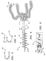
- FIG. 3 illustrates a simple electrical diagram of a power supply circuit 130 for supplying a first current to the assembly 10 in the manner described above.
- Points A, B of the circuit 130 may correspond to or otherwise may be coupled to points A, B of the assembly 10.
- the direction of DC current is shown in the electrical diagram of FIG. 3 .
- the first current may be AC current.
- the first current passes through the electrolytic sacrificial joint 40 without causing the joint 40 to separate because an overall resistance Rd of the thermo-resistive elements 110 (not shown in FIG. 6 for simplicity) of the device 30 is less than a resistance Rm of the electrolytic path or medium (e.g., blood) between the exposed, conductive wires 70, 80.
- Some current leakage from the wires 70, 80 may result in some corrosion of the wires 70, 80, but current leakage may be controlled by designing or adjusting the resistivity Rd of the device 30.
- Using AC current for the first current helps to inhibit accidental corrosion of the wires 70, 80.
- a second current in the same direction is supplied to the wires 50, 60 by a circuit 140 such as that shown in FIG. 5 .
- the second current returns to a ground or return electrode 150 on or in the patient.
- a bias between the two wires 70, 80 and the ground 150 causes the electrolytically sacrificial joint to corrode and separate, as shown in FIG. 4 .
- the second current is maintained until the device 30 has detached from the rest of the assembly 10.
- a thrombus forms in the aneurysm and is shortly thereafter complemented with thrombus and eventually, a collagenous material, which significantly lessens the potential for aneurysm rupture.
- the detachable thermo-sensitive embolic device assembly 10 may cause more uniform heating of the embolic device 30 and more consistent performance.
- the assembly 10 also overcomes other problems associated with saline heating, such as differential mixing of saline with blood due to dissimilar thermodynamics, non-uniform heat distribution, heat transfer out of the catheter, and physician compliance in maintaining reasonable saline temperature and injection rates.
- the detachable device assembly may include an electrolytically detachable device with one or more electrically responsive elements in addition to (a) thermo-electric element(s).
- electrically responsive elements include microelectromechanical systems electrically stimulated contractile elements, light emitting diodes, piezoelectric crystals, electromagnetic elements, or sensors.
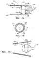
- an interference fit joint 240 may be provided that may simultaneously mechanically secure and electrically couple an embolic device or other electrically responsive element 230 to a delivery member 220 to provide a unitary assembly 210.
- the interference fit joint 240 may include a bulbous member or other connector 242 that extends from the electrically responsive element 230, for example, from the hub 90 of the embolic device 30 (not shown, see FIG. 2 ).
- the connector 242 includes contacts or other electrically conductive regions 244a, 244b thereon, e.g., extending around the bulbous member 242 and spaced apart axially from one another that are coupled to respective leads 245.
- the leads 245 may be coupled to an electrically responsive element (not shown), such as those described above.
- the delivery member 220 e.g., a catheter or other tubular member, includes mating connectors 222 including contacts or other electrically conductive regions 224a, 224b thereon and a lumen or other recess 226 defined by the connectors 222.
- Leads 225 may extend from the contacts 224, e.g., proximally within a wall of the delivery member 220, to a source of electrical energy (not shown).
- the connectors 222 on the delivery member 220 may be annular ribs that extend inwardly into the lumen 222 with the contacts 224a, 224b thereon.
- the bulbous member 242 may be a fluid-filled or solid body biased to expand to a size large than the lumen 222, yet sufficiently flexible to allow insertion into the lumen 222.
- the ribs 222 may grip or otherwise engage the bulbous member 242 when it is received in the lumen 226, thereby securing the bulbous member 242, and, consequently, the electrically responsive element 230 to the delivery member 220.
- the contacts 224, 244 may be coupled to one another, thereby electrically coupling the leads 225, 245 to one another, and, consequently, the electrically responsive element 230 to the source of electrical energy.
- the connectors 222' may be longitudinal gripping elements that are spaced apart about the circumference of the lumen 226, e.g., disposed opposite one another.
- contacts 244a', 244b' may be provided on the bulbous member 242' that may cooperate with the contacts 224' on the delivery member 220,' e.g., may be disposed opposite one another and extend axially along the bulbous member 242.'
- the leads 225', 245' may be coupled to one another, similar to the previous embodiment.
- the connector(s) 222 on the delivery member 220 may be disengaged from the bulbous member 242 to release the electrically responsive element 230 from the delivery member 220.
- the delivery member 220 may be expandable to direct the connectors 222 away from one another, thereby increasing the size of the lumen 226, as shown in FIG. 7C .
- the connectors 222 may be gripping elements (not shown) that may be mechanically actuated from a proximal end (not shown) of the delivery member 220 to release the electrically responsive element 230.
- the bulbous member 242 may be compressible inwardly to release the electrically responsive element 230 (not shown).
- the bulbous member 242 may be resiliently compressible such that it may be forced into the lumen 226 and held frictionally between the connectors 222.
- a fluid or pusher member (not shown) may be introduced into the lumen 226 with sufficient pressure to overcome the interference fit and push the bulbous member 242 out of the lumen 226.
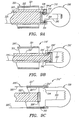
- FIG. 9A another embodiment of an assembly 310 is shown that includes a delivery device 320 and a detachable device 330, e.g., an electrically responsive device, as described above.
- the delivery device 320 generally includes a catheter or other tubular member 321 and a pusher member 322 slidably disposed within a lumen 323 of the catheter 321.
- the pusher member 322 includes a recess 326 within a distal end thereof for receiving a hub or other connector 342 extending from the detachable device 330.
- Leads 325, 345 in the catheter 321 and the pusher member 322 may be coupled to one another by cooperating contacts 324, 344 when the hub 342 is fully received within the recess 326.
- the hub 342 may be secured within the recess 326 by an interference fit, an electrolytic sacrificial joint, mechanical connector(s), and the like, similar to the embodiments described above.
- the contacts 324, 344 may include a relatively thin conductive wire connecting them that may be eroded upon application of a predetermined electrical current.
- the hub 342 may be slidably received within the recess 326, e.g., by friction, yet deployable by pushing the hub 342 out of the recess 326, e.g., using an internal or external pusher element (not shown) that may be advanced distally relative to the pusher member 322 against the hub 342.
- the detachable device 330 may be disposed within the lumen 323 of the catheter 321, and the catheter 321 may be advanced, e.g., endoluminally within a patient's vasculature, to a target site, e.g., an aneurysm within a cranial artery or other blood vessel (not shown).
- the catheter 321 may be advanced to the target site, e.g., over a guidewire (not shown), and then the pusher member 322 with the detachable device 330 thereon may be delivered through the lumen 323 of the catheter 321.
- the pusher member 322 may be advanced distally to expose the detachable device 330.
- Electrical energy from a power source may be delivered to the detachable device 330, via the leads 325, 345, e.g., to heat and/or expand the detachable device 330, similar to the embodiments described above.
- the detachable device 330 may then be deployed, i.e., released, from the pusher member 322, whereupon the catheter 312 and pusher member 322 may be withdrawn, leaving the detachable device 330 at the target site.
- a pusher member 322' may include a hub 326' and a detachable device 330' may include a recess 342.
- Leads 325,' 345' and contacts 324,' 344' may be provided, similar to the previous embodiment.
- the detachable device 330' may be releasably secured to the pusher member 322' and/or may be deployed similar to the previous embodiment.
- FIG. 9C yet another alternative embodiment of an assembly 310" is shown that includes a delivery device 320," including a catheter 321" and a pusher member 322" slidably disposed within a lumen 323" of the catheter 321, and a detachable device 330, similar to the previous embodiments.
- the catheter 321" includes contacts 324" and leads 325,” which may be coupled to an electrical power source (not shown).
- a hub 342" of the detachable device 330 may be received in the lumen 323" such that contacts 344 on the hub 342" contact the contacts 324" on the catheter 321,” thereby coupling the detachable device 330 to the power source.
- the pusher member 322" may include a distal end 326" that may abut the hub 342 such that, upon advancement of the pusher member 322," the hub 342 may be pushed out of the lumen 323" to deploy the detachable device 330.
- the distal end 326" of the pusher member 322" and/or the hub 342 may include one or more connectors (not shown) for releasably connecting the detachable device 330 to the pusher member 322.”
- FIGS. 10A-10C embodiments of detachable joints are shown that use induction current transfer to transfer electrical energy to an electrically responsive element, rather than physical contacts, as described above.
- an assembly 410 is shown that includes a delivery device 420, including a catheter 421 and a pusher member 422, and a detachable device 430.
- the pusher member 422 may include a recess 426 for receiving a hub 442 extending from the detachable device 430, similar to the previous embodiments.
- the pusher member 422 includes a coil 424 coupled to leads 425, and the hub 442 includes a coil 444 coupled to leads 445.
- the coil 424 on the pusher member 422 may surround the recess 426 such that the coil 424 may be inductively coupled to the coil 444 when the hub 442 is received in the recess 426.
- electrical energy e.g., from an RF generator (not shown) coupled to the leads 425, may be delivered to the detachable device 430 via the concentric coils 424, 444, as is known to those skilled in the art.
- the hub 442 may be secured within the recess 426 by an interference fit and/or cooperating connectors (not shown), similar to the previous embodiments, that allow the detachable device 430 to be deployed from the delivery device 420.
- the hub 442 may be secured within the recess 426 by an interference fit and/or one or more mechanical connectors.
- the pusher member 422' may include a hub 426' that may be received within a recess 442 within the detachable device 430.'
- the catheter 420" may include a coil 424" that may surround the coil 444 when the hub 442 is received in a lumen 423" of the catheter 421" to inductively couple the leads 425," 445 to one another.
- the pusher member 422" and/or the hub 442 may include cooperating connectors (not shown), e.g., on a distal end 426" of the pusher member 422” for detachably securing the detachable device 430 to the pusher member 422," similar to the embodiments described above. Delivery and/or deployment of the detachable device 430 may proceed similar to the previous embodiments, except that a direct electrical connection is not necessary.
Landscapes
- Health & Medical Sciences (AREA)
- Surgery (AREA)
- Life Sciences & Earth Sciences (AREA)
- Molecular Biology (AREA)
- General Health & Medical Sciences (AREA)
- Vascular Medicine (AREA)
- Engineering & Computer Science (AREA)
- Biomedical Technology (AREA)
- Heart & Thoracic Surgery (AREA)
- Medical Informatics (AREA)
- Reproductive Health (AREA)
- Animal Behavior & Ethology (AREA)
- Nuclear Medicine, Radiotherapy & Molecular Imaging (AREA)
- Public Health (AREA)
- Veterinary Medicine (AREA)
- Neurosurgery (AREA)
- Surgical Instruments (AREA)
- Heterocyclic Carbon Compounds Containing A Hetero Ring Having Oxygen Or Sulfur (AREA)
- Pharmaceuticals Containing Other Organic And Inorganic Compounds (AREA)
- Steroid Compounds (AREA)
- Media Introduction/Drainage Providing Device (AREA)
- Saccharide Compounds (AREA)
- Measurement Of The Respiration, Hearing Ability, Form, And Blood Characteristics Of Living Organisms (AREA)
Claims (16)
- Ensemble de dispositif détachable pour traiter un patient, comprenant :un dispositif détachable (30, 330, 430, 430') comprenant un élément de sensibilité électrique (100, 230) pouvant être activé en faisant passer un premier courant électrique à travers l'élément de sensibilité électrique ;un dispositif d'acheminement (20, 220, 220', 320, 420, 420', 420") pour acheminer le dispositif détachable (30, 330, 430, 430') à un emplacement ciblé dans un patient ; etun joint détachable (40, 240) reliant le dispositif détachable au dispositif d'acheminement et adapté pour déployer le dispositif détachable depuis le dispositif d' acheminement ;caractérisé en ce que l'élément de sensibilité électrique change de forme lorsque le premier courant électrique passe à travers l'élément de sensibilité électrique, l'élément de sensibilité électrique (100, 230) comprenant un élément thermorésistant (110) qui fournit de la chaleur au dispositif détachable (30, 330, 430, 430') au passage du premier courant électrique, le dispositif détachable étant configuré pour prendre une forme prédéfinie en réaction à la chaleur.
- Ensemble selon la revendication 1, dans lequel le dispositif d'acheminement comprend un cathéter (321, 321", 421, 421', 421 ").
- Ensemble selon la revendication 1, dans lequel le dispositif d'acheminement comprend un fil de poussée (50).
- Ensemble selon la revendication 1, dans lequel le dispositif détachable (30, 330, 430, 430') comprend un matériau à mémoire de forme thermosensible (120) qui prend une forme prédéfinie lorsqu'il est chauffé par l'élément thermorésistant (110).
- Ensemble selon la revendication 1, dans lequel le dispositif détachable (30, 330, 430, 430') comprend un élément à mémoire de forme thermorésistant, et un polymère (120), le polymère maintenant le dispositif détachable dans une configuration compacte, et étant adapté pour se déformer lorsqu'il est chauffé par l'élément à mémoire de forme thermorésistant.
- Ensemble selon la revendication 1, dans lequel l'élément thermorésistant (110) est réalisé à partir d'un alliage platine-tungstène (PtW).
- Ensemble selon la revendication 1, dans lequel l'élément thermorésistant (110) comprend un fil thermorésistant.
- Ensemble selon la revendication 1, dans lequel l'élément thermorésistant (110) comprend un film fin.
- Ensemble selon la revendication 1, dans lequel l'élément thermorésistant (110) est radio-opaque.
- Ensemble selon la revendication 1, dans lequel le joint (24, 240) comprend un joint sacrificiel électrolytique (24) reliant le dispositif détachable (30, 330, 430, 430') et le dispositif d'acheminement (20, 220, 220', 320, 420, 420', 420"), et adapté pour se détacher au passage d'un second courant électrique le traversant pour déployer le dispositif détachable vers l'emplacement ciblé.
- Ensemble selon la revendication 10, dans lequel le joint sacrificiel électrolytique (24) comprend un premier fil conducteur (70) et un second fil conducteur (80) avec un circuit électrolytique entre eux, le circuit électrolytique présentant une résistance électrique, et l'élément thermorésistant du dispositif détachable (30, 330, 430, 430') présentant une résistance électrique inférieure à la résistance électrique du circuit électrolytique.
- Ensemble selon la revendication 1, dans lequel le joint (24, 240) comprend un connecteur mécanique sur au moins l'un parmi le dispositif d'acheminement (20, 220, 220', 320, 420, 420', 420") et le dispositif détachable (30, 330, 430, 430').
- Ensemble selon la revendication 1, dans lequel le joint (24, 240) comprend un connecteur externe (222) sur l'un parmi le dispositif détachable (30, 330, 430, 430') et le dispositif d'acheminement (220, 220'), et un connecteur interne (242) sur l'autre du dispositif détachable et du dispositif d'acheminement, au moins l'un des connecteurs externe et interne étant configuré pour changer de forme pour libérer le dispositif détachable du dispositif d'acheminement.
- Ensemble selon la revendication 13, dans lequel un connecteur externe (222) peut être dilaté pour libérer le connecteur interne (242) du connecteur externe.
- Ensemble selon la revendication 14, dans lequel le connecteur interne (242) peut être comprimé pour libérer le connecteur interne du connecteur externe (222).
- Ensemble selon la revendication 1, dans lequel l'emplacement ciblé comprend un anévrisme.
Applications Claiming Priority (3)
| Application Number | Priority Date | Filing Date | Title |
|---|---|---|---|
| US29568 | 2001-12-20 | ||
| US10/029,568 US6953473B2 (en) | 2001-12-20 | 2001-12-20 | Detachable device with electrically responsive element |
| PCT/US2002/040270 WO2003053281A1 (fr) | 2001-12-20 | 2002-12-16 | Dispositif detachable dote d'un element de sensibilite electrique |
Publications (2)
| Publication Number | Publication Date |
|---|---|
| EP1460968A1 EP1460968A1 (fr) | 2004-09-29 |
| EP1460968B1 true EP1460968B1 (fr) | 2009-05-06 |
Family
ID=21849704
Family Applications (1)
| Application Number | Title | Priority Date | Filing Date |
|---|---|---|---|
| EP02805603A Expired - Lifetime EP1460968B1 (fr) | 2001-12-20 | 2002-12-16 | Dispositif detachable dote d'un element de sensibilite electrique |
Country Status (8)
| Country | Link |
|---|---|
| US (1) | US6953473B2 (fr) |
| EP (1) | EP1460968B1 (fr) |
| JP (1) | JP4334349B2 (fr) |
| AT (1) | ATE430531T1 (fr) |
| AU (1) | AU2002357276A1 (fr) |
| CA (1) | CA2468554A1 (fr) |
| DE (1) | DE60232272D1 (fr) |
| WO (1) | WO2003053281A1 (fr) |
Families Citing this family (96)
| Publication number | Priority date | Publication date | Assignee | Title |
|---|---|---|---|---|
| US6890303B2 (en) * | 2001-05-31 | 2005-05-10 | Matthew Joseph Fitz | Implantable device for monitoring aneurysm sac parameters |
| US8715312B2 (en) | 2001-07-20 | 2014-05-06 | Microvention, Inc. | Aneurysm treatment device and method of use |
| US8252040B2 (en) | 2001-07-20 | 2012-08-28 | Microvention, Inc. | Aneurysm treatment device and method of use |
| US7572288B2 (en) * | 2001-07-20 | 2009-08-11 | Microvention, Inc. | Aneurysm treatment device and method of use |
| US7207946B2 (en) * | 2002-05-09 | 2007-04-24 | Spiration, Inc. | Automated provision of information related to air evacuation from a chest cavity |
| US20040034405A1 (en) * | 2002-07-26 | 2004-02-19 | Dickson Andrew M. | Axially expanding polymer stent |
| US7308738B2 (en) * | 2002-10-19 | 2007-12-18 | General Motors Corporation | Releasable fastener systems and processes |
| US7013538B2 (en) | 2002-10-19 | 2006-03-21 | General Motors Corporation | Electroactive polymer releasable fastening system and method of use |
| US6983517B2 (en) * | 2002-10-19 | 2006-01-10 | General Motors Corporation | Releasable fastener system |
| US7032282B2 (en) | 2002-10-19 | 2006-04-25 | General Motors Corporation | Releasable fastener system |
| US7146690B2 (en) * | 2002-10-19 | 2006-12-12 | General Motors Corporation | Releasable fastener system |
| US7140081B2 (en) * | 2002-10-19 | 2006-11-28 | General Motors Corporation | Releasable fastener system |
| US6973701B2 (en) * | 2002-10-19 | 2005-12-13 | General Motors Corporation | Releasable fastening system based on ionic polymer metal composites and method of use |
| US7013536B2 (en) | 2002-10-19 | 2006-03-21 | General Motors Corporation | Releasable fastener systems and processes |
| US6944920B2 (en) * | 2002-10-19 | 2005-09-20 | General Motors Corporation | Electrostatically releasable fastening system and method of use |
| JP4015983B2 (ja) * | 2002-10-19 | 2007-11-28 | ゼネラル・モーターズ・コーポレーション | 解除可能な付属品用の磁気粘性ナノ複合エラストマー |
| US8123774B2 (en) * | 2003-03-20 | 2012-02-28 | Boston Scientific Scimed, Inc. | Piezoelectric vascular implant release device |
| AU2004241111B2 (en) | 2003-05-15 | 2010-05-27 | Dsm Ip Assets B.V | Manufacture and use of implantable reticulated elastomeric matrices |
| US7219113B2 (en) * | 2003-09-26 | 2007-05-15 | International Business Machines Corporation | Pseudo-random binary sequence checker with automatic synchronization |
| US20070135907A1 (en) * | 2003-10-02 | 2007-06-14 | The Regents Of The University Of California | Stent with expandable foam |
| US7763077B2 (en) | 2003-12-24 | 2010-07-27 | Biomerix Corporation | Repair of spinal annular defects and annulo-nucleoplasty regeneration |
| ATE448737T1 (de) | 2004-09-22 | 2009-12-15 | Dendron Gmbh | Vorrichtung zur implantation von mikrowendeln |
| US7879064B2 (en) | 2004-09-22 | 2011-02-01 | Micro Therapeutics, Inc. | Medical implant |
| US7455670B2 (en) * | 2005-01-14 | 2008-11-25 | Co-Repair, Inc. | System and method for the treatment of heart tissue |
| US8025668B2 (en) * | 2005-04-28 | 2011-09-27 | C. R. Bard, Inc. | Medical device removal system |
| US20060261109A1 (en) * | 2005-05-18 | 2006-11-23 | Browne Alan L | Cargo container including an active material based releasable fastener system |
| US20070100414A1 (en) * | 2005-11-02 | 2007-05-03 | Cardiomind, Inc. | Indirect-release electrolytic implant delivery systems |
| CA2649702C (fr) | 2006-04-17 | 2014-12-09 | Microtherapeutics, Inc. | Systeme et procede destines a positionner mecaniquement des implants intravasculaires |
| EP2124762B1 (fr) | 2007-03-13 | 2013-09-11 | Covidien LP | Implant comprenant une bobine et un élément résistant à l'étirement |
| AU2008254770A1 (en) | 2007-05-18 | 2008-11-27 | Stryker Corporation | Medical implant detachment systems |
| EP2157937B1 (fr) | 2007-06-04 | 2017-03-22 | Sequent Medical, Inc. | Dispositifs pour le traitement de défauts vasculaires |
| EP2162101B1 (fr) | 2007-06-25 | 2019-02-20 | MicroVention, Inc. | Prothèse auto-expansible |
| US20090099638A1 (en) * | 2007-10-11 | 2009-04-16 | Med Institute, Inc. | Motorized deployment system |
| WO2009073398A1 (fr) * | 2007-12-03 | 2009-06-11 | Boston Scientific Scimed, Inc. | Dispositif implantable avec une jonction détachable de façon électrolytique ayant de multiples câbles minces |
| EP2231030B1 (fr) | 2007-12-21 | 2019-02-27 | MicroVention, Inc. | Système et procédé permettant de localiser une zone de détachement d'un implant amovible |
| JP5367721B2 (ja) | 2007-12-21 | 2013-12-11 | マイクロベンション インコーポレイテッド | インプラント分離を検出するシステムおよび方法 |
| US11583289B2 (en) * | 2008-05-01 | 2023-02-21 | Aneuclose Llc | Aneurysm-occluding mesh ribbon with a series of loops or segments having distal-to-proximal variation in size, shape, and/or orientation |
| EP2279023B1 (fr) | 2008-05-02 | 2020-12-02 | Sequent Medical, Inc. | Dispositifs filamentaires pour le traitement de défauts vasculaires |
| US20100069948A1 (en) * | 2008-09-12 | 2010-03-18 | Micrus Endovascular Corporation | Self-expandable aneurysm filling device, system and method of placement |
| AU2009303677B2 (en) * | 2008-10-13 | 2014-04-24 | Stryker European Holdings I, Llc | Vaso-occlusive coil delivery system |
| EP2405830A2 (fr) * | 2009-03-13 | 2012-01-18 | Boston Scientific Scimed, Inc. | Contact électrique pour système de distribution de dispositif occlusif |
| US20100256666A1 (en) * | 2009-04-06 | 2010-10-07 | Boston Scientific Scimed, Inc. | Delivery wire for occlusive device delivery system |
| WO2010120694A1 (fr) * | 2009-04-16 | 2010-10-21 | Boston Scientific Scimed, Inc. | Contact électrique pour système de mise en place de dispositif d'occlusion |
| US20100268251A1 (en) * | 2009-04-16 | 2010-10-21 | Boston Scientific Scimed, Inc. | Delivery wire for occlusive device delivery system and method of manufacture |
| US9314250B2 (en) | 2009-04-16 | 2016-04-19 | Stryker Corporation | Electrical contact for occlusive device delivery system |
| WO2011057002A2 (fr) | 2009-11-05 | 2011-05-12 | Sequent Medical Inc. | Dispositifs filamentaires multicouches pour le traitement d'anomalies vasculaires |
| US20110118776A1 (en) * | 2009-11-18 | 2011-05-19 | Boston Scientific Scimed, Inc. | Delivery wire assembly for occlusive device delivery system |
| EP2531119A1 (fr) * | 2010-02-05 | 2012-12-12 | Stryker NV Operations Ltd | Appareil de traitement d'occlusion et de sténose à mode multiple et procédé d'utilisation |
| WO2012155093A1 (fr) | 2011-05-11 | 2012-11-15 | Microvention, Inc. | Dispositif permettant d'occlure une lumière |
| US8945171B2 (en) | 2011-09-29 | 2015-02-03 | Covidien Lp | Delivery system for implantable devices |
| US8795313B2 (en) | 2011-09-29 | 2014-08-05 | Covidien Lp | Device detachment systems with indicators |
| US9579104B2 (en) | 2011-11-30 | 2017-02-28 | Covidien Lp | Positioning and detaching implants |
| US9011480B2 (en) | 2012-01-20 | 2015-04-21 | Covidien Lp | Aneurysm treatment coils |
| US9687245B2 (en) | 2012-03-23 | 2017-06-27 | Covidien Lp | Occlusive devices and methods of use |
| US8920459B2 (en) * | 2012-03-30 | 2014-12-30 | DePuy Synthes Products, LLC | Embolic coil detachment mechanism with flexible distal member and resistive electrical heating element |
| US9808255B2 (en) * | 2012-03-30 | 2017-11-07 | DePuy Synthes Products, Inc. | Embolic coil detachment mechanism with flexible distal member, resistive electrical heating element and shape memory polymer element |
| US9980731B2 (en) * | 2012-03-30 | 2018-05-29 | DePuy Synthes Products, Inc. | Embolic coil detachment mechanism with flexible distal member and coupling union |
| US9326774B2 (en) | 2012-08-03 | 2016-05-03 | Covidien Lp | Device for implantation of medical devices |
| US8597323B1 (en) | 2012-11-16 | 2013-12-03 | Sequent Medical, Inc. | Delivery and detachment systems and methods for vascular implants |
| US9955976B2 (en) | 2013-08-16 | 2018-05-01 | Sequent Medical, Inc. | Filamentary devices for treatment of vascular defects |
| US9078658B2 (en) | 2013-08-16 | 2015-07-14 | Sequent Medical, Inc. | Filamentary devices for treatment of vascular defects |
| WO2015057735A1 (fr) | 2013-10-15 | 2015-04-23 | Cedars-Sinai Medical Center | Valvule mitrale transcathéter à auto-positionnement et à orientation anatomique |
| US10543078B2 (en) | 2013-10-16 | 2020-01-28 | Cedars-Sinai Medical Center | Modular dis-assembly of transcatheter valve replacement devices and uses thereof |
| EP3057522B1 (fr) | 2013-10-17 | 2019-10-09 | Cedars-Sinai Medical Center | Dispositif pour traiter par voie percutanée l'embolisation de valvule cardiaque |
| EP3079633B1 (fr) | 2013-12-11 | 2023-01-18 | Cedars-Sinai Medical Center | Dispositif de remplacement transcathéter de la valve mitrale dans une valve mitrale à deux orifices |
| US10507301B2 (en) | 2014-01-31 | 2019-12-17 | Cedars-Sinai Medical Center | Pigtail for optimal aortic valvular complex imaging and alignment |
| US9629635B2 (en) | 2014-04-14 | 2017-04-25 | Sequent Medical, Inc. | Devices for therapeutic vascular procedures |
| US9713475B2 (en) | 2014-04-18 | 2017-07-25 | Covidien Lp | Embolic medical devices |
| US9808256B2 (en) | 2014-08-08 | 2017-11-07 | Covidien Lp | Electrolytic detachment elements for implant delivery systems |
| US9814466B2 (en) | 2014-08-08 | 2017-11-14 | Covidien Lp | Electrolytic and mechanical detachment for implant delivery systems |
| US9782178B2 (en) | 2014-09-19 | 2017-10-10 | DePuy Synthes Products, Inc. | Vasculature occlusion device detachment system with tapered corewire and heater activated fiber detachment |
| US9855050B2 (en) | 2014-09-19 | 2018-01-02 | DePuy Synthes Products, Inc. | Vasculature occlusion device detachment system with tapered corewire and single loop fuse detachment |
| US10869756B2 (en) | 2015-03-12 | 2020-12-22 | Cedars-Sinai Medical Center | Devices, systems, and methods to optimize annular orientation of transcatheter valves |
| US9717503B2 (en) | 2015-05-11 | 2017-08-01 | Covidien Lp | Electrolytic detachment for implant delivery systems |
| US10245072B2 (en) | 2015-07-10 | 2019-04-02 | Medtronic, Inc. | Extravascular medical access tools having boring tip and methods of using such tools |
| US10758729B2 (en) | 2015-10-01 | 2020-09-01 | Medtronic, Inc. | Interventional medical systems, catheters, and methods |
| US9844664B2 (en) | 2015-10-12 | 2017-12-19 | Medtronic, Inc. | Interventional medical systems, catheters, and subassemblies |
| US10434283B2 (en) | 2015-10-29 | 2019-10-08 | Medtronic, Inc. | Interventional medical systems, associated assemblies and methods |
| US10080888B2 (en) | 2015-11-16 | 2018-09-25 | Medtronic, Inc. | Interventional medical systems and associated methods |
| US10828037B2 (en) | 2016-06-27 | 2020-11-10 | Covidien Lp | Electrolytic detachment with fluid electrical connection |
| US10828039B2 (en) | 2016-06-27 | 2020-11-10 | Covidien Lp | Electrolytic detachment for implantable devices |
| US11051822B2 (en) | 2016-06-28 | 2021-07-06 | Covidien Lp | Implant detachment with thermal activation |
| WO2018022954A1 (fr) * | 2016-07-29 | 2018-02-01 | The Texas A&M University System | Dispositif d'injection d'un cathéter endovasculaire chauffé |
| US10576099B2 (en) | 2016-10-21 | 2020-03-03 | Covidien Lp | Injectable scaffold for treatment of intracranial aneurysms and related technology |
| US11376039B2 (en) | 2017-03-30 | 2022-07-05 | Medtronic, Inc. | Interventional medical systems and associated assemblies |
| US10874402B2 (en) | 2017-10-10 | 2020-12-29 | Boston Scientific Scimed, Inc. | Detachable RF energized occlusive device |
| US12114863B2 (en) | 2018-12-05 | 2024-10-15 | Microvention, Inc. | Implant delivery system |
| CN113573650B (zh) | 2019-03-15 | 2024-05-28 | 后续医疗股份有限公司 | 用于治疗血管缺陷的具有柔性连接部的丝装置 |
| US11317921B2 (en) | 2019-03-15 | 2022-05-03 | Sequent Medical, Inc. | Filamentary devices for treatment of vascular defects |
| US11559309B2 (en) | 2019-03-15 | 2023-01-24 | Sequent Medical, Inc. | Filamentary devices for treatment of vascular defects |
| WO2021092619A1 (fr) | 2019-11-04 | 2021-05-14 | Covidien Lp | Systèmes et méthodes de traitement d'anévrismes |
| US20210282789A1 (en) | 2020-03-11 | 2021-09-16 | Microvention, Inc. | Multiple layer devices for treatment of vascular defects |
| US12070220B2 (en) | 2020-03-11 | 2024-08-27 | Microvention, Inc. | Devices having multiple permeable shells for treatment of vascular defects |
| US12023034B2 (en) | 2020-03-11 | 2024-07-02 | Microvention, Inc. | Devices for treatment of vascular defects |
| CN114431917B (zh) * | 2020-11-06 | 2025-06-06 | 微创优通医疗科技(嘉兴)有限公司 | 一种止血夹 |
| US12446891B2 (en) | 2021-08-30 | 2025-10-21 | Microvention, Inc. | Devices for treatment of vascular defects |
Family Cites Families (22)
| Publication number | Priority date | Publication date | Assignee | Title |
|---|---|---|---|---|
| US5851206A (en) * | 1990-03-13 | 1998-12-22 | The Regents Of The University Of California | Method and apparatus for endovascular thermal thrombosis and thermal cancer treatment |
| US6083220A (en) | 1990-03-13 | 2000-07-04 | The Regents Of The University Of California | Endovascular electrolytically detachable wire and tip for the formation of thrombus in arteries, veins, aneurysms, vascular malformations and arteriovenous fistulas |
| US5122136A (en) | 1990-03-13 | 1992-06-16 | The Regents Of The University Of California | Endovascular electrolytically detachable guidewire tip for the electroformation of thrombus in arteries, veins, aneurysms, vascular malformations and arteriovenous fistulas |
| US5354295A (en) | 1990-03-13 | 1994-10-11 | Target Therapeutics, Inc. | In an endovascular electrolytically detachable wire and tip for the formation of thrombus in arteries, veins, aneurysms, vascular malformations and arteriovenous fistulas |
| US5569245A (en) | 1990-03-13 | 1996-10-29 | The Regents Of The University Of California | Detachable endovascular occlusion device activated by alternating electric current |
| PT703761E (pt) * | 1993-03-11 | 2003-06-30 | Mark M Friedman | Extensor |
| IL105828A (en) * | 1993-05-28 | 1999-06-20 | Medinol Ltd | Medical stent |
| US5498227A (en) * | 1993-09-15 | 1996-03-12 | Mawad; Michel E. | Retrievable, shielded radiotherapy implant |
| US5423829A (en) | 1993-11-03 | 1995-06-13 | Target Therapeutics, Inc. | Electrolytically severable joint for endovascular embolic devices |
| US5669905A (en) | 1994-03-03 | 1997-09-23 | Target Therapeutics, Inc. | Endovascular embolic device detachment detection method and apparatus |
| US5578074A (en) * | 1994-12-22 | 1996-11-26 | Target Therapeutics, Inc. | Implant delivery method and assembly |
| US5749894A (en) * | 1996-01-18 | 1998-05-12 | Target Therapeutics, Inc. | Aneurysm closure method |
| US5964797A (en) * | 1996-08-30 | 1999-10-12 | Target Therapeutics, Inc. | Electrolytically deployable braided vaso-occlusion device |
| US5911737A (en) | 1997-02-28 | 1999-06-15 | The Regents Of The University Of California | Microfabricated therapeutic actuators |
| US6156061A (en) | 1997-08-29 | 2000-12-05 | Target Therapeutics, Inc. | Fast-detaching electrically insulated implant |
| JPH11197250A (ja) * | 1997-10-30 | 1999-07-27 | Kaneka Medics:Kk | 生体内留置部材配置用ワイヤー装置 |
| JPH11137694A (ja) * | 1997-11-13 | 1999-05-25 | Takiron Co Ltd | 生体内分解吸収性の形状記憶ステント |
| US6113622A (en) | 1998-03-10 | 2000-09-05 | Cordis Corporation | Embolic coil hydraulic deployment system |
| US6165194A (en) * | 1998-07-24 | 2000-12-26 | Micrus Corporation | Intravascular flow modifier and reinforcement device |
| US6478773B1 (en) * | 1998-12-21 | 2002-11-12 | Micrus Corporation | Apparatus for deployment of micro-coil using a catheter |
| US6296622B1 (en) | 1998-12-21 | 2001-10-02 | Micrus Corporation | Endoluminal device delivery system using axially recovering shape memory material |
| US6648911B1 (en) * | 2000-11-20 | 2003-11-18 | Avantec Vascular Corporation | Method and device for the treatment of vulnerable tissue site |
-
2001
- 2001-12-20 US US10/029,568 patent/US6953473B2/en not_active Expired - Fee Related
-
2002
- 2002-12-16 JP JP2003554042A patent/JP4334349B2/ja not_active Expired - Fee Related
- 2002-12-16 WO PCT/US2002/040270 patent/WO2003053281A1/fr not_active Ceased
- 2002-12-16 AU AU2002357276A patent/AU2002357276A1/en not_active Abandoned
- 2002-12-16 DE DE60232272T patent/DE60232272D1/de not_active Expired - Lifetime
- 2002-12-16 EP EP02805603A patent/EP1460968B1/fr not_active Expired - Lifetime
- 2002-12-16 CA CA002468554A patent/CA2468554A1/fr not_active Abandoned
- 2002-12-16 AT AT02805603T patent/ATE430531T1/de not_active IP Right Cessation
Also Published As
| Publication number | Publication date |
|---|---|
| JP2005512674A (ja) | 2005-05-12 |
| JP4334349B2 (ja) | 2009-09-30 |
| AU2002357276A1 (en) | 2003-07-09 |
| US6953473B2 (en) | 2005-10-11 |
| CA2468554A1 (fr) | 2003-07-03 |
| DE60232272D1 (de) | 2009-06-18 |
| ATE430531T1 (de) | 2009-05-15 |
| EP1460968A1 (fr) | 2004-09-29 |
| US20030120300A1 (en) | 2003-06-26 |
| WO2003053281A1 (fr) | 2003-07-03 |
Similar Documents
| Publication | Publication Date | Title |
|---|---|---|
| US6953473B2 (en) | Detachable device with electrically responsive element | |
| US6224610B1 (en) | Shape memory polymer intravascular delivery system with heat transfer medium | |
| US6500149B2 (en) | Apparatus for deployment of micro-coil using a catheter | |
| US7780680B2 (en) | Apparatus for deployment of micro-coil using a catheter | |
| US9808255B2 (en) | Embolic coil detachment mechanism with flexible distal member, resistive electrical heating element and shape memory polymer element | |
| JP2874850B2 (ja) | 電気分解的に離脱可能なインプラントのための送達カテーテル | |
| EP2644129B1 (fr) | Mécanisme de détachement de spirale embolique avec élément distale flexible et raccord de couplage | |
| US20050149108A1 (en) | Implant delivery and detachment system and method | |
| EP2752163A2 (fr) | Mécanisme de détachement de spirale embolique avec longe de polymère | |
| JPH07265431A (ja) | 生体内留置部材を有する医療用ワイヤー | |
| US20130023922A1 (en) | Apparatus and method for deployment of a therapeutic device using a catheter | |
| US20090270901A1 (en) | Degradable detachment mechanisms for implantable devices | |
| KR20160034221A (ko) | 테이퍼 형성된 코어와이어 및 단일 루프 융해 결합해제를 갖는 혈관구조 폐색 장치 결합해제 시스템 | |
| CA2441396C (fr) | Dispositif de mise en place d'un dicro-serpentin a l'aide d'un catheter |
Legal Events
| Date | Code | Title | Description |
|---|---|---|---|
| PUAI | Public reference made under article 153(3) epc to a published international application that has entered the european phase |
Free format text: ORIGINAL CODE: 0009012 |
|
| 17P | Request for examination filed |
Effective date: 20040611 |
|
| AK | Designated contracting states |
Kind code of ref document: A1 Designated state(s): AT BE BG CH CY CZ DE DK EE ES FI FR GB GR IE IT LI LU MC NL PT SE SI SK TR |
|
| AX | Request for extension of the european patent |
Extension state: AL LT LV MK RO |
|
| RAP1 | Party data changed (applicant data changed or rights of an application transferred) |
Owner name: BOSTON SCIENTIFIC LIMITED |
|
| GRAP | Despatch of communication of intention to grant a patent |
Free format text: ORIGINAL CODE: EPIDOSNIGR1 |
|
| GRAS | Grant fee paid |
Free format text: ORIGINAL CODE: EPIDOSNIGR3 |
|
| GRAA | (expected) grant |
Free format text: ORIGINAL CODE: 0009210 |
|
| AK | Designated contracting states |
Kind code of ref document: B1 Designated state(s): AT BE BG CH CY CZ DE DK EE ES FI FR GB GR IE IT LI LU MC NL PT SE SI SK TR |
|
| REG | Reference to a national code |
Ref country code: GB Ref legal event code: FG4D |
|
| REG | Reference to a national code |
Ref country code: CH Ref legal event code: EP |
|
| REG | Reference to a national code |
Ref country code: IE Ref legal event code: FG4D |
|
| REF | Corresponds to: |
Ref document number: 60232272 Country of ref document: DE Date of ref document: 20090618 Kind code of ref document: P |
|
| PG25 | Lapsed in a contracting state [announced via postgrant information from national office to epo] |
Ref country code: FI Free format text: LAPSE BECAUSE OF FAILURE TO SUBMIT A TRANSLATION OF THE DESCRIPTION OR TO PAY THE FEE WITHIN THE PRESCRIBED TIME-LIMIT Effective date: 20090506 Ref country code: PT Free format text: LAPSE BECAUSE OF FAILURE TO SUBMIT A TRANSLATION OF THE DESCRIPTION OR TO PAY THE FEE WITHIN THE PRESCRIBED TIME-LIMIT Effective date: 20090906 Ref country code: AT Free format text: LAPSE BECAUSE OF FAILURE TO SUBMIT A TRANSLATION OF THE DESCRIPTION OR TO PAY THE FEE WITHIN THE PRESCRIBED TIME-LIMIT Effective date: 20090506 Ref country code: ES Free format text: LAPSE BECAUSE OF FAILURE TO SUBMIT A TRANSLATION OF THE DESCRIPTION OR TO PAY THE FEE WITHIN THE PRESCRIBED TIME-LIMIT Effective date: 20090817 |
|
| NLV1 | Nl: lapsed or annulled due to failure to fulfill the requirements of art. 29p and 29m of the patents act | ||
| PG25 | Lapsed in a contracting state [announced via postgrant information from national office to epo] |
Ref country code: SI Free format text: LAPSE BECAUSE OF FAILURE TO SUBMIT A TRANSLATION OF THE DESCRIPTION OR TO PAY THE FEE WITHIN THE PRESCRIBED TIME-LIMIT Effective date: 20090506 Ref country code: SE Free format text: LAPSE BECAUSE OF FAILURE TO SUBMIT A TRANSLATION OF THE DESCRIPTION OR TO PAY THE FEE WITHIN THE PRESCRIBED TIME-LIMIT Effective date: 20090806 Ref country code: NL Free format text: LAPSE BECAUSE OF FAILURE TO SUBMIT A TRANSLATION OF THE DESCRIPTION OR TO PAY THE FEE WITHIN THE PRESCRIBED TIME-LIMIT Effective date: 20090506 |
|
| PG25 | Lapsed in a contracting state [announced via postgrant information from national office to epo] |
Ref country code: DK Free format text: LAPSE BECAUSE OF FAILURE TO SUBMIT A TRANSLATION OF THE DESCRIPTION OR TO PAY THE FEE WITHIN THE PRESCRIBED TIME-LIMIT Effective date: 20090506 Ref country code: EE Free format text: LAPSE BECAUSE OF FAILURE TO SUBMIT A TRANSLATION OF THE DESCRIPTION OR TO PAY THE FEE WITHIN THE PRESCRIBED TIME-LIMIT Effective date: 20090506 Ref country code: CZ Free format text: LAPSE BECAUSE OF FAILURE TO SUBMIT A TRANSLATION OF THE DESCRIPTION OR TO PAY THE FEE WITHIN THE PRESCRIBED TIME-LIMIT Effective date: 20090506 |
|
| PG25 | Lapsed in a contracting state [announced via postgrant information from national office to epo] |
Ref country code: BE Free format text: LAPSE BECAUSE OF FAILURE TO SUBMIT A TRANSLATION OF THE DESCRIPTION OR TO PAY THE FEE WITHIN THE PRESCRIBED TIME-LIMIT Effective date: 20090506 Ref country code: SK Free format text: LAPSE BECAUSE OF FAILURE TO SUBMIT A TRANSLATION OF THE DESCRIPTION OR TO PAY THE FEE WITHIN THE PRESCRIBED TIME-LIMIT Effective date: 20090506 |
|
| PLBE | No opposition filed within time limit |
Free format text: ORIGINAL CODE: 0009261 |
|
| STAA | Information on the status of an ep patent application or granted ep patent |
Free format text: STATUS: NO OPPOSITION FILED WITHIN TIME LIMIT |
|
| PG25 | Lapsed in a contracting state [announced via postgrant information from national office to epo] |
Ref country code: BG Free format text: LAPSE BECAUSE OF FAILURE TO SUBMIT A TRANSLATION OF THE DESCRIPTION OR TO PAY THE FEE WITHIN THE PRESCRIBED TIME-LIMIT Effective date: 20090806 |
|
| 26N | No opposition filed |
Effective date: 20100209 |
|
| PG25 | Lapsed in a contracting state [announced via postgrant information from national office to epo] |
Ref country code: MC Free format text: LAPSE BECAUSE OF NON-PAYMENT OF DUE FEES Effective date: 20100701 |
|
| REG | Reference to a national code |
Ref country code: CH Ref legal event code: PL |
|
| GBPC | Gb: european patent ceased through non-payment of renewal fee |
Effective date: 20091216 |
|
| REG | Reference to a national code |
Ref country code: FR Ref legal event code: ST Effective date: 20100831 |
|
| PG25 | Lapsed in a contracting state [announced via postgrant information from national office to epo] |
Ref country code: LI Free format text: LAPSE BECAUSE OF NON-PAYMENT OF DUE FEES Effective date: 20091231 Ref country code: GR Free format text: LAPSE BECAUSE OF FAILURE TO SUBMIT A TRANSLATION OF THE DESCRIPTION OR TO PAY THE FEE WITHIN THE PRESCRIBED TIME-LIMIT Effective date: 20090807 Ref country code: FR Free format text: LAPSE BECAUSE OF NON-PAYMENT OF DUE FEES Effective date: 20091231 Ref country code: CH Free format text: LAPSE BECAUSE OF NON-PAYMENT OF DUE FEES Effective date: 20091231 |
|
| PG25 | Lapsed in a contracting state [announced via postgrant information from national office to epo] |
Ref country code: GB Free format text: LAPSE BECAUSE OF NON-PAYMENT OF DUE FEES Effective date: 20091216 |
|
| PGFP | Annual fee paid to national office [announced via postgrant information from national office to epo] |
Ref country code: IE Payment date: 20101126 Year of fee payment: 9 |
|
| PGFP | Annual fee paid to national office [announced via postgrant information from national office to epo] |
Ref country code: IT Payment date: 20101213 Year of fee payment: 9 |
|
| PG25 | Lapsed in a contracting state [announced via postgrant information from national office to epo] |
Ref country code: LU Free format text: LAPSE BECAUSE OF NON-PAYMENT OF DUE FEES Effective date: 20091216 |
|
| PGFP | Annual fee paid to national office [announced via postgrant information from national office to epo] |
Ref country code: DE Payment date: 20101230 Year of fee payment: 9 |
|
| PG25 | Lapsed in a contracting state [announced via postgrant information from national office to epo] |
Ref country code: TR Free format text: LAPSE BECAUSE OF FAILURE TO SUBMIT A TRANSLATION OF THE DESCRIPTION OR TO PAY THE FEE WITHIN THE PRESCRIBED TIME-LIMIT Effective date: 20090506 |
|
| PG25 | Lapsed in a contracting state [announced via postgrant information from national office to epo] |
Ref country code: CY Free format text: LAPSE BECAUSE OF FAILURE TO SUBMIT A TRANSLATION OF THE DESCRIPTION OR TO PAY THE FEE WITHIN THE PRESCRIBED TIME-LIMIT Effective date: 20090506 |
|
| REG | Reference to a national code |
Ref country code: IE Ref legal event code: MM4A |
|
| REG | Reference to a national code |
Ref country code: DE Ref legal event code: R119 Ref document number: 60232272 Country of ref document: DE Effective date: 20120703 |
|
| PG25 | Lapsed in a contracting state [announced via postgrant information from national office to epo] |
Ref country code: IE Free format text: LAPSE BECAUSE OF NON-PAYMENT OF DUE FEES Effective date: 20111216 Ref country code: DE Free format text: LAPSE BECAUSE OF NON-PAYMENT OF DUE FEES Effective date: 20120703 |
|
| PG25 | Lapsed in a contracting state [announced via postgrant information from national office to epo] |
Ref country code: IT Free format text: LAPSE BECAUSE OF NON-PAYMENT OF DUE FEES Effective date: 20111216 |