EP1460993B1 - Adaptateur discret utilise avec un catheter medical - Google Patents
Adaptateur discret utilise avec un catheter medical Download PDFInfo
- Publication number
- EP1460993B1 EP1460993B1 EP02799072A EP02799072A EP1460993B1 EP 1460993 B1 EP1460993 B1 EP 1460993B1 EP 02799072 A EP02799072 A EP 02799072A EP 02799072 A EP02799072 A EP 02799072A EP 1460993 B1 EP1460993 B1 EP 1460993B1
- Authority
- EP
- European Patent Office
- Prior art keywords
- adaptor
- stem
- channel
- shaped
- tube
- Prior art date
- Legal status (The legal status is an assumption and is not a legal conclusion. Google has not performed a legal analysis and makes no representation as to the accuracy of the status listed.)
- Expired - Lifetime
Links
Images


Classifications
-
- A—HUMAN NECESSITIES
- A61—MEDICAL OR VETERINARY SCIENCE; HYGIENE
- A61J—CONTAINERS SPECIALLY ADAPTED FOR MEDICAL OR PHARMACEUTICAL PURPOSES; DEVICES OR METHODS SPECIALLY ADAPTED FOR BRINGING PHARMACEUTICAL PRODUCTS INTO PARTICULAR PHYSICAL OR ADMINISTERING FORMS; DEVICES FOR ADMINISTERING FOOD OR MEDICINES ORALLY; BABY COMFORTERS; DEVICES FOR RECEIVING SPITTLE
- A61J15/00—Feeding-tubes for therapeutic purposes
- A61J15/0015—Gastrostomy feeding-tubes
-
- A—HUMAN NECESSITIES
- A61—MEDICAL OR VETERINARY SCIENCE; HYGIENE
- A61J—CONTAINERS SPECIALLY ADAPTED FOR MEDICAL OR PHARMACEUTICAL PURPOSES; DEVICES OR METHODS SPECIALLY ADAPTED FOR BRINGING PHARMACEUTICAL PRODUCTS INTO PARTICULAR PHYSICAL OR ADMINISTERING FORMS; DEVICES FOR ADMINISTERING FOOD OR MEDICINES ORALLY; BABY COMFORTERS; DEVICES FOR RECEIVING SPITTLE
- A61J15/00—Feeding-tubes for therapeutic purposes
- A61J15/0026—Parts, details or accessories for feeding-tubes
- A61J15/0053—Means for fixing the tube outside of the body, e.g. by a special shape, by fixing it to the skin
- A61J15/0057—Means for fixing the tube outside of the body, e.g. by a special shape, by fixing it to the skin fixing a tube end, i.e. tube not protruding the fixing means
-
- A—HUMAN NECESSITIES
- A61—MEDICAL OR VETERINARY SCIENCE; HYGIENE
- A61M—DEVICES FOR INTRODUCING MEDIA INTO, OR ONTO, THE BODY; DEVICES FOR TRANSDUCING BODY MEDIA OR FOR TAKING MEDIA FROM THE BODY; DEVICES FOR PRODUCING OR ENDING SLEEP OR STUPOR
- A61M39/00—Tubes, tube connectors, tube couplings, valves, access sites or the like, specially adapted for medical use
- A61M39/22—Valves or arrangement of valves
- A61M39/26—Valves closing automatically on disconnecting the line and opening on reconnection thereof
-
- A—HUMAN NECESSITIES
- A61—MEDICAL OR VETERINARY SCIENCE; HYGIENE
- A61J—CONTAINERS SPECIALLY ADAPTED FOR MEDICAL OR PHARMACEUTICAL PURPOSES; DEVICES OR METHODS SPECIALLY ADAPTED FOR BRINGING PHARMACEUTICAL PRODUCTS INTO PARTICULAR PHYSICAL OR ADMINISTERING FORMS; DEVICES FOR ADMINISTERING FOOD OR MEDICINES ORALLY; BABY COMFORTERS; DEVICES FOR RECEIVING SPITTLE
- A61J15/00—Feeding-tubes for therapeutic purposes
- A61J15/0026—Parts, details or accessories for feeding-tubes
-
- A—HUMAN NECESSITIES
- A61—MEDICAL OR VETERINARY SCIENCE; HYGIENE
- A61J—CONTAINERS SPECIALLY ADAPTED FOR MEDICAL OR PHARMACEUTICAL PURPOSES; DEVICES OR METHODS SPECIALLY ADAPTED FOR BRINGING PHARMACEUTICAL PRODUCTS INTO PARTICULAR PHYSICAL OR ADMINISTERING FORMS; DEVICES FOR ADMINISTERING FOOD OR MEDICINES ORALLY; BABY COMFORTERS; DEVICES FOR RECEIVING SPITTLE
- A61J2205/00—General identification or selection means
- A61J2205/30—Printed labels
-
- A—HUMAN NECESSITIES
- A61—MEDICAL OR VETERINARY SCIENCE; HYGIENE
- A61M—DEVICES FOR INTRODUCING MEDIA INTO, OR ONTO, THE BODY; DEVICES FOR TRANSDUCING BODY MEDIA OR FOR TAKING MEDIA FROM THE BODY; DEVICES FOR PRODUCING OR ENDING SLEEP OR STUPOR
- A61M39/00—Tubes, tube connectors, tube couplings, valves, access sites or the like, specially adapted for medical use
- A61M39/10—Tube connectors; Tube couplings
- A61M39/1011—Locking means for securing connection; Additional tamper safeties
-
- A—HUMAN NECESSITIES
- A61—MEDICAL OR VETERINARY SCIENCE; HYGIENE
- A61M—DEVICES FOR INTRODUCING MEDIA INTO, OR ONTO, THE BODY; DEVICES FOR TRANSDUCING BODY MEDIA OR FOR TAKING MEDIA FROM THE BODY; DEVICES FOR PRODUCING OR ENDING SLEEP OR STUPOR
- A61M39/00—Tubes, tube connectors, tube couplings, valves, access sites or the like, specially adapted for medical use
- A61M39/10—Tube connectors; Tube couplings
- A61M39/12—Tube connectors; Tube couplings for joining a flexible tube to a rigid attachment
-
- A—HUMAN NECESSITIES
- A61—MEDICAL OR VETERINARY SCIENCE; HYGIENE
- A61M—DEVICES FOR INTRODUCING MEDIA INTO, OR ONTO, THE BODY; DEVICES FOR TRANSDUCING BODY MEDIA OR FOR TAKING MEDIA FROM THE BODY; DEVICES FOR PRODUCING OR ENDING SLEEP OR STUPOR
- A61M39/00—Tubes, tube connectors, tube couplings, valves, access sites or the like, specially adapted for medical use
- A61M39/22—Valves or arrangement of valves
-
- Y—GENERAL TAGGING OF NEW TECHNOLOGICAL DEVELOPMENTS; GENERAL TAGGING OF CROSS-SECTIONAL TECHNOLOGIES SPANNING OVER SEVERAL SECTIONS OF THE IPC; TECHNICAL SUBJECTS COVERED BY FORMER USPC CROSS-REFERENCE ART COLLECTIONS [XRACs] AND DIGESTS
- Y10—TECHNICAL SUBJECTS COVERED BY FORMER USPC
- Y10S—TECHNICAL SUBJECTS COVERED BY FORMER USPC CROSS-REFERENCE ART COLLECTIONS [XRACs] AND DIGESTS
- Y10S128/00—Surgery
- Y10S128/912—Connections and closures for tubes delivering fluids to or from the body
-
- Y—GENERAL TAGGING OF NEW TECHNOLOGICAL DEVELOPMENTS; GENERAL TAGGING OF CROSS-SECTIONAL TECHNOLOGIES SPANNING OVER SEVERAL SECTIONS OF THE IPC; TECHNICAL SUBJECTS COVERED BY FORMER USPC CROSS-REFERENCE ART COLLECTIONS [XRACs] AND DIGESTS
- Y10—TECHNICAL SUBJECTS COVERED BY FORMER USPC
- Y10S—TECHNICAL SUBJECTS COVERED BY FORMER USPC CROSS-REFERENCE ART COLLECTIONS [XRACs] AND DIGESTS
- Y10S604/00—Surgery
- Y10S604/905—Aseptic connectors or couplings, e.g. frangible, piercable
Definitions
- the present invention relates generally to medical catheters, such as gastrostomy feeding tubes, and relates more particularly to low profile adaptors well-suited for use with medical catheters.
- Certain patients are unable to take food transorally due to an inability to swallow. Such an inability to swallow may be due to a variety of reasons, such as esophageal cancer, neurological impairment and the like.
- the intravenous administration of food to such patients may be a viable short-term approach, it is not well-suited for the long-term. Accordingly, the most common approach to the long-term feeding of such patients involves gastrostomy, i.e., the creation of a feeding tract or stoma between the stomach and the upper abdominal wall.
- Feeding is then typically performed by administering food through a feeding tube that has been inserted into the feeding tract, with the distal end of the feeding tube extending into the stomach and being retained therein by an internal anchor or bolster and the proximal end of the feeding tube extending through the abdominal wall.
- the endoscopic snare loop is then used to grasp the wire, the cannula is released, and the endoscope and wire are withdrawn through the esophagus and mouth of the patient.
- a silicone gastrostomy feeding tube the distal end of which is attached to a silicone, dome-shaped internal bolster, is then secured to the wire and is pulled from its proximal end through the esophagus and into the stomach until the internal bolster engages the stomach wall and the feeding tube extends through the stomach and abdominal walls, with the proximal end of the feeding tube extending approximately one foot beyond the abdominal wall.
- an external bolster is typically secured to the feeding tube to engage the abdomen so as to prevent longitudinal movement of the feeding tube within the stoma tract.
- a "Y-port" adapter is typically attached to the proximal end of the feeding tube, the Y-port adapter being adapted to receive a pair of connector tips through which food and/or medications may be dispensed.
- a detachable locking clip is typically secured to the feeding tube at a point between the external bolster and the Y-port adapter to prevent gastric fluids from escaping through the proximal end of the feeding tube when the feeding tube is not in use.
- the low-profile replacement PEG device of said patent comprises a deformable, conical tip portion having at least one side aperture therethrough, a tube portion which extends rearwardly from the tip portion, a fitting portion on the rear end of the tube portion, a removable valve portion in the fitting portion and a flange portion which extends outwardly from the fitting portion.
- the device is adapted to be installed in a patient so that the tube portion extends through a preestablished stoma with the tip portion located in the patient's stomach and with the fitting portion and the flange portion engaging the skin of the patient adjacent the stoma.
- the deformable tip portion of the above-described low-profile replacement PEG device functions as an internal bolster to anchor its associated tube portion in a patient's stomach.
- an obturator or similar device is typically inserted through the tube portion and is used to elongate or otherwise deform the tip portion in such a way as to permit the tip portion to fit through the stoma. Removal of the obturator from the tip portion then permits the tip portion to expand to its original shape for anchoring.
- Another type of low-profile replacement PEG device uses an inflatable balloon, instead of a deformable tip portion, as an internal bolster to retain the distal end of its associated tube within a patient's stomach.
- the inflatable balloon is deflated, the distal end of the tube portion is inserted through the stoma, and the balloon is then inflated.
- the balloon is deflated and the tube is then withdrawn from the stoma.
- low-profile replacement PEG devices are less awkward and bulky than initially-implanted gastrostomy tube assemblies
- the use of such low-profile replacement PEG devices suffers from its own set of shortcomings.
- One such shortcoming is that the implantation of a low-profile replacement PEG device must be preceded by the removal of an intially-implanted gastrostomy tube. Such removal typically involves pulling on the proximal end of the gastrostomy tube until the internal bolster fails and is drawn through the stoma.
- Such a procedure can be quite painful to the patient and can result in damage to the stoma, thereby delaying when the replacement device can be implanted.
- the adaptor is said to comprise an anti-reflux valve assembly having a stem which can be plugged into the open end of the feeding tube.
- the valve assembly is said to contain a seal which functions as a one-way valve to prevent reflux of gastric contents but which permits the introduction of feeding solution into the feeding tube.
- a clamp is placed around the feeding tube and the valve stem and is locked into place to secure the valve assembly to the feeding tube at a location flush with the patient's skin.
- a silicone cover is placed around the clamp to protect the patient from skin irritation caused by the clamp and also to protect the clamp and valve assembly from contaminants.
- valve assembly of the subject adaptor relies upon the use of a silicone gasket having a Y-shaped slot through which a cannula is typically inserted to deliver food and/or medications.
- a silicone gasket having a Y-shaped slot through which a cannula is typically inserted to deliver food and/or medications.
- such a silicone gasket after repeated insertions of the cannula therethrough, has a tendency to tear or to otherwise fail to act reliably as a one-way valve. Consequently, because the adaptor cannot easily be disconnected from the gastrostomy feeding tube once connected thereto, replacement of a worn adaptor requires the removal and replacement of the gastrostomy tube as well.
- Still another shortcoming with the aforementioned adaptor is that the clamp of said adaptor has a tendency to pinch the proximal end of the gastrostomy tube at those points where the male and female sections of the clamp are joined. Such pinching, over time, has a tendency to cause the tube to tear.
- an adaptor well-suited for use with a medical catheter such as gastrostomy feeding tube
- said adaptor comprising (a) a body, said body being provided with a first channel and a second channel, said first channel and said second channel being in fluid communication with one another, said first channel being adapted for fluid communication with a medical catheter; and (b) a stem, said stem having a front end, a rear end, a side wall, a cavity extending rearwardly from said front end, and a hole in said side wall in fluid communication with said cavity, said stem being mounted within said second channel of said body and being rotatable between an open position in which said stem and said first channel are in fluid communication with one another via said hole and a closed position in which said stem and said first channel are not in fluid communication with one another.
- the adaptor comprises a body having a lower portion and an upper portion.
- a first channel is provided in the lower portion, and a second channel is provided in the upper portion, the first and second channels being perpendicular to and in fluid communication with one another.
- a generally cylindrical stem is coaxially positioned within the second channel, the stem being rotatably mounted about its longitudinal axis.
- the stem is hollow and has an open front end, a closed rear end and a hole in its side wall, the hole being rotatably alignable with the first channel.
- a stop is formed on the exterior of the stem, the stop being engageable with a surface positioned within the second channel.
- the front end of the stem is recessed relative to the front end of the second channel to prevent unwanted rotation of the stem.
- An external thread is formed on the front end of the stem. Rotation of the stem from a closed position to an open position is achieved by screwing onto the front end of the stem an internally threaded member that matingly engages the external thread on the front end of the stem.
- the proximal end of the gastrostomy feeding tube is inserted over the lower portion of the body and is secured thereto with a nut.
- the adaptors discussed above are described as being low profile adaptors, such adaptors are also suitable for use with medical catheters, such as gastrostomy feeding tubes, that extend externally for several inches. Accordingly, the adaptors of the present invention are not limited to being low profile adaptors.
- the present invention is also directed to a PEG device comprising a gastrostomy feeding tube having a proximal end and a distal end, an internal bolster secured to the distal end of the gastrostomy feeding tube, and an adaptor of the type described above secured to the proximal end of the gastrostomy feeding tube.
- a low profile adaptor constructed according to the teachings of the present invention for use with a medical catheter, such as a gastrostomy feeding tube, said low profile adaptor being represented generally by reference numeral 11.
- Body 13 which is preferably made of molded medical grade plastic, is a unitary member shaped to include a lower portion 15 and an upper portion 17, lower portion 15 extending generally vertically and upper portion 17 extending generally horizontally and being positioned over lower portion 15.
- a lumen 25 having a circular cross-section extends longitudinally through support 19 and steps 21 and 23 and continues for a short distance into upper portion 17 for reasons to become apparent below.
- tube support 19 and step 21 are appropriately dimensioned so that a gastrostomy feeding tube GT may be inserted thereover.
- step 23 is provided with external threads 27.
- Upper portion 17 which, when viewed from above, has an hourglass shape to facilitate its being grasped with the thumb and forefinger of an operator, is provided with a channel that extends rearwardly from the front end 33 of upper portion 17 to a point prior to the rear end 35 of upper portion 17, said channel being shaped to include a front portion 37, an intermediate portion 39 and a rear portion 41.
- Front portion 37 is rectangular in transverse cross-section and is centered within front end 33 of upper portion 17 so that a rectangular shield 43 is formed bounding front portion 37 on all four sides thereof.
- Intermediate portion 39 which is smaller in overall transverse cross-sectional area than front portion 37, is equidistantly spaced between the left and right sides 43-1 and 43-2, respectively, of shield 43 and is shaped to define a left side 45, a right side 47, a bottom and an open top, said open top extending through the top 51 of upper portion 17 and serving as a window 53 for reasons to become apparent below.
- Said bottom of intermediate portion 39 is shaped to include a semi-circular groove 49 flanked on opposite sides by stop surfaces 55 and 57, the functions of groove 49 and stop surfaces 55 and 57 also to become apparent below.
- Rear portion 41 of the channel of upper portion 17 is generally cylindrical in shape, the bottom half of rear portion 41 being aligned with and sized to match groove 49.
- a groove 59 of increased transverse cross-sectional area is formed within rear portion 41 proximate to the front end thereof, the function of groove 59 to be discussed below.
- Rear portion 41 is in fluid communication with lumen 25 for reasons to become apparent below, with the rear end 61 of rear portion 41 extending just beyond lumen 25.
- Adaptor 11 also comprises an elongated tube or stem 71 (shown separately in Fig. 6 ), stem 71 being rotatably mounted about its longitudinal axis within the aforementioned channel of upper portion 17.
- Stem 71 which is preferably made of molded medical grade plastic, is a generally cylindrical unitary member shaped to include a front end 73, a rear end 75 and a side wall 77.
- Stem 71 is sized so that front end 73 is spaced rearwardly relative to front end 33 of upper portion 17, with rear end 75 flush against rear end 61 of upper portion 17.
- Front end 73 is shaped to define a radially outwardly extending collar. Threads 79 are formed on the exterior perimeter of front end 73 for reasons to become apparent below.
- a channel is formed in stem 71, said channel comprising a front portion 81 and a rear portion 83.
- Front portion 81 extends rearwardly from front end 73 a short distance and is inwardly tapered from front end 73 to matingly receive a medical luer.
- Rear portion 83 which is generally cylindrical in shape, extends rearwardly from front portion 81 to a point just before rear end 75.
- a hole 85 is formed in side wall 77 for accessing rear portion 83, hole 85 being alignable, depending upon the rotational position of stem 71, with lumen 25.
- a stop block 87 is formed on the outside surface of side wall 77 for engaging stop surfaces 55 and 57, thereby delimiting the rotation of stem 71.
- An annular snap seal 89 is formed on the outside surface of side wall 77, snap seal 89 fitting into groove 59 so to keep stem 71 in place longitudinally within upper portion 17.
- Adaptor 11 further comprises a ring-shaped member or nut 91, nut 91 serving as an external bolster for a gastrostomy feeding tube and being used to secure the gastrostomy feeding tube to body 13.
- Nut 91 which is preferably made of molded medical grade plastic, is a generally annular unitary member comprising a top surface 93, a bottom surface 95, an outer surface 97 and a central bore. The central bore is shaped to include a lower portion 99, an intermediate portion 101 and an upper portion 103. Lower portion 99 is appropriately dimensioned to securely receive tube support 19 and a gastrostomy feeding tube GT inserted thereover. Intermediate portion 101 is appropriately dimensioned to securely receive step 21 and the proximal end of the gastrostomy feeding tube GT.
- Upper portion 103 is appropriately dimensioned to securely receive step 23, upper portion 103 being provided with internal threads 105 for mating with external threads 27 of step 23.
- a gastrostomy feeding tube is implanted in a patient by a physician in the manner described above so that the distal end of the tube is positioned in the patient's stomach and retained therein using an internal bolster, with the proximal end of the tube extending externally for a distance of several inches (2,54cm).
- the physician or other medical care giver
- the physician then cuts the implanted gastrostomy feeding tube to a desired length.
- Nut 91 is then inserted over the proximal end of the gastrostomy feeding tube and is moved distally across the gastrostomy feeding tube until it is positioned against the patient's skin.
- a conventional syringe or tube of the type having at one end a medical luer surrounded by an internally threaded sleeve is shown in Fig. 7 , which depicts a syringe 111 having a front end shaped to include a medical luer 113 surrounded by a sleeve 115, sleeve 115 being provided with an internal thread 117.
- luer 113 is inserted into front portion 81 of the channel of stem 71, and sleeve 115 is rotated clockwise.
- Initial rotation of sleeve 115 causes threads 117 to engage threads 79 of stem 71 and results in the rotation of stem 71 from its closed position wherein stop block 87 is positioned on top of stop surface 57 and hole 85 is turned approximately 180 degrees away from lumen 25 to its open position wherein stop block 87 is positioned on top of stop surface 55 and hole is aligned with lumen 25.
- sleeve 115 is visible through window 53, and printed indicators on top 51 of upper portion 17 proximate to window 53 may be used to assist an operator in identifying whether stop block 87 is in an open or closed position.
- sleeve 115 will tighten the engagement of sleeve 115 to stem 71 but will not result in further rotation of stem 71 due to stop surface 55.
- food and/or medications may be dispensed from syringe 111 through adaptor 11.
- sleeve 115 is rotated counterclockwise, causing stop block 87 to be moved from its open position on top of stop surface 55 to its closed position engaged with stop surface 57.
- sleeve 115 will disengage sleeve 115 and luer 113 from stem 71, without further rotation of stem 71 due to stop surface 57.
- adaptor 11 as compared to existing valve-type adaptors of the type described above, is that its lumen size, in the open position, is not restricted. Another advantage is that adaptor 11 cannot easily be moved from a closed position to an open position, unless a device like syringe 111 is attached thereto. Still another advantage is that a device like syringe 111 cannot easily be pulled out of adaptor 11 when adaptor 11 is in its open position. Still yet another advantage is that adaptor 11, when in its open position, is connected to the delivery system in such a way as to prevent leakage of the fluids being administered to the patient and, when in its closed position, does not permit bodily fluids from the patient to escape therethrough.
- low-profile adaptor 11 could alternatively be attached to the proximal end of a jejunostomy feeding tube or could be used as a low-profile replacement enteral feeding device.
- adaptor 11 could also be used for fluid drainage, for example, by being attached to a urine or blood drainage catheter.
- body 13 is constructed in the present embodiment so that lumen 25 and the channel formed in upper portion 17 are perpendicular, one could adjust the angle therebetween, for example, enlarging the angle therebetween to facilitate alignment of a syringe with stem 71.
- a low profile adaptor constructed according to the teachings of the present invention for use with a medical catheter, such as a gastrostomy feeding tube, said low profile adaptor being represented generally by reference numeral 151.
- Adaptor 151 is similar in most respects to adaptor 11, one difference between the two adaptors being that adaptor 151 comprises an upper portion 153 that, when viewed from above, is oval-shaped, as opposed to being hour-glass-shaped. Another difference is that the front end 155 of upper portion 153 is shaped to shield stem 71 from the top and bottom, but not from the sides. Still another difference is that adaptor 151 comprises a nut 157 whose outer surface 159 includes a beveled region 161. Referring now to Figs.
- FIG. 10 and 11 there are shown top and section views of a third embodiment of a low profile adaptor constructed according to the teachings of the present invention for use with a medical catheter, such as a gastrostomy feeding tube, said low profile adaptor being represented generally by reference numeral 201.
- Adaptor 201 is similar in most respects to adaptor 11, one difference between the two adaptors being that adaptor 201 comprises an upper portion 203 that, when viewed from above, is generally rectangular with rounded ends, as opposed to being hourglass-shaped. Another difference is that adaptor 201 comprises a nut 205 having an outwardly extending flange 207. Still another difference is that adaptor 201 comprises a stem 209 having an open rear end 211.
- Fig. 12 there is shown a perspective view of a fourth embodiment of a low profile adaptor constructed according to the teachings of the present invention for use with a gastrostomy feeding tube, said low profile adaptor being represented generally by reference numeral 251.
- Adaptor 251 is similar in many respects to adaptor 11, one difference between the two adaptors being that adaptor 251 has an upper portion 253 that is generally cylindrical in shape, as opposed to being hourglass-shaped. Another difference is that adaptor 251 does not include a nut that serves as an external bolster. Instead, adaptor 251 has a lower portion 255 that is shaped to include an outwardly extending circumferential flange 257, flange 257 serving as an external bolster.
- the bottom of lower portion 255 is shaped to include a circumferential ridge 259, ridge 259 being appropriately dimensioned so that the proximal end of a gastrostomy feeding tube may be inserted over ridge 259 and secured thereto by some securing mechanism, such as a ratchet-type clamp (not shown).
- some securing mechanism such as a ratchet-type clamp (not shown).
- the bottom of lower portion 255 could simply be barb-shaped, with no additional mechanism being used to secure a gastrostomy feeding tube thereto.
- a fifth embodiment of a low profile adaptor constructed according to the teachings of the present invention for use with a gastrostomy feeding tube said low profile adaptor being represented generally by reference numeral 301.
- Adaptor 301 is similar in many respects to adaptor 11, one difference between the two adaptors being that, whereas adaptor 11 has a body 13 that is hourglass-shaped when viewed from above, adaptor 301 has a body 303 that, when viewed from above, includes a generally rectangular front portion 305 and a generally circular rear portion 307.
- adaptor 301 includes a nut 311, nut 311 being identical to nut 91, except that nut 311 is provided with a cylindrical cavity 313 extending radially inwardly from its outer surface 315 to a point prior to its inner bore.
- Adaptor 301 further includes a rod 317, rod 317 being insertable into cavity 313 to facilitate the tightening of nut 311 around a gastrostomy feeding tube and body 303.
- adaptor 301 includes a stem 321, stem 321 being identical to stem 71, except that stem 321 has a front end 323 shaped to define a semi-annular tongue, instead of front end 73, which is provided with threads. Front end 323 is set back relative to front 306 of front portion 305.
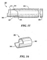
- Fig. 15 there is shown a side view, broken away in part, of a tube assembly suitable for use with adaptor 301, said tube assembly being represented generally by reference numeral 351.
- Assembly 351 includes a delivery tube 353 for use in conveying food and/or medications to a patient, delivery tube 353 having a proximal end 355 and a distal end 357.
- Assembly 351 also includes a hollow connector 361 (shown separately in Fig. 16 ), connector 361 having a proximal end 363 and a distal end 365. Proximal end 363 is inserted into distal end 357 of tube 353 and is retained therein by glue or a friction fit.
- Distal end 365 of connector 361 is shaped to define a semi-annular tongue dimensioned complemetarily to front end 323 of stem 321 so that distal end 365 of connector 361 can be fitted together with front end 323 of stem 321 and, thereafter, can be used to rotate stem 321.
- An O-ring 371 is securely mounted over connector 361, O-ring 371 being positioned on connector 361 so as to be received in groove 309 when connector 361 and stem 321 are fitted together. In this manner, engagement of connector 361 against stem 321 may be maintained.
- distal end 365 of connector 361 and front end 323 of stem 321 in the present embodiment are illustrative only; other mating or otherwise engageable arrangements for connector 361 and stem 321 could also be used.
- assembly 351 could alternatively be used for draining fluids from a patient.
Landscapes
- Health & Medical Sciences (AREA)
- Veterinary Medicine (AREA)
- Life Sciences & Earth Sciences (AREA)
- Animal Behavior & Ethology (AREA)
- General Health & Medical Sciences (AREA)
- Public Health (AREA)
- Pulmonology (AREA)
- Heart & Thoracic Surgery (AREA)
- Gastroenterology & Hepatology (AREA)
- Engineering & Computer Science (AREA)
- Anesthesiology (AREA)
- Biomedical Technology (AREA)
- Hematology (AREA)
- Infusion, Injection, And Reservoir Apparatuses (AREA)
- Medical Preparation Storing Or Oral Administration Devices (AREA)
Claims (31)
- Un adaptateur (11, 151, 201, 251, 301) bien approprié à une utilisation avec un cathéter médical, ledit adaptateur (11, 151, 201, 251, 301) comprenant:un corps (13, 303), ledit corps étant pourvu d'un premier canal (25) et d'un second canal, ledit premier canal (25) et ledit second canal étant en communication de fluide l'un avec l'autre, ledit premier canal (25) étant apte à une communication de fluide avec le cathéter médical ; etune tige (71, 209, 321), ladite tige (71, 209, 321) possédant une extrémité avant (73, 323), un arrière (75, 211), une paroi latérale (77), une cavité (81) s'étendant vers l'arrière à partir de ladite extrémité avant (73, 323), et un orifice (85) dans ladite paroi latérale (77) en communication de fluide avec ladite cavité (81), ladite tige (71, 209, 321) étant montée à l'intérieur dudit second canal dudit corps (13, 303) et pouvant tourner entre une position ouverte dans laquelle ladite tige (71, 209, 321) et ledit premier canal (25) sont en communication de fluide l'un avec l'autre via ledit orifice (85) et une position fermée dans laquelle ladite tige (71, 209, 321) et ledit premier canal (25) ne sont pas en communication de fluide l'un avec l'autre ;ledit adaptateur (11, 151, 201, 251, 301) étant caractérisé en ce que ledit second canal possède une extrémité avant et en ce que ladite extrémité avant (73, 323) de ladite tige (71, 209, 321) est espacée vers l'arrière par rapport à ladite extrémité avant dudit second canal.
- L'adaptateur (11, 151, 201, 251, 301) de la revendication 1, dans lequel ledit corps (13, 303) est conformé de manière à inclure une partie supérieure (17, 153, 203, 253) et une partie inférieure (15, 255), ladite partie supérieure (17, 153, 203, 253) étant disposée par-dessus ladite partie inférieure (15, 255).
- L'adaptateur (11, 151, 201, 251, 301) de la revendication 2, dans lequel ladite partie inférieure (15, 255) est généralement cylindrique et est conformée pour inclure un tube support (19, 259), ledit tube support (19, 259) pouvant être inséré à l'intérieur de l'extrémité proximale du cathéter médical, ledit tube support (19, 259) entourant au moins une partie dudit premier canal (25).
- L'adaptateur (11, 151, 201, 251, 301) de la revendication 3, dans lequel ledit second canal est disposé à l'intérieur de ladite partie supérieure (17, 153, 203, 253), ledit second canal étant accessible à partir de l'avant (33, 155, 306) de ladite partie supérieure (17, 153, 203, 253).
- L'adaptateur (11, 151, 201, 251, 301) de la revendication 4, dans lequel ledit premier canal (25) et ledit second canal sont globalement perpendiculaires l'un à l'autre.
- L'adaptateur (11, 151, 201, 301) de la revendication 3, comprenant en outre des moyens pour assujettir le cathéter médical à ladite partie inférieure (15).
- L'adaptateur (11, 151, 201, 301) de la revendication 6, dans lequel lesdits moyens de solidarisation comprennent un organe de forme annulaire (91, 157, 205, 311), ledit organe de forme annulaire (91, 157, 205, 311) pouvant être inséré au-dessus du cathéter médical et de ladite partie inférieure (15).
- L'adaptateur (301) de la revendication 7, dans lequel ledit organe de forme annulaire (311) est pourvu d'un évidement (313) s'étendant radialement vers l'intérieur à partir de sa surface extérieure (315), ledit adaptateur (301) comprenant en outre une tige (317) pouvant être insérée dans ledit évidement (313).
- L'adaptateur (11, 151, 201, 301) de la revendication 3, dans lequel ladite partie inférieure (15) est en outre conformée pour inclure au moins un degré avec un diamètre extérieur croissant (21, 23) par-dessus ledit tube support (19).
- L'adaptateur (11, 151, 201, 301) de la revendication 3, dans lequel ladite portion inférieure (15) est en outre conformée pour inclure des degrés supérieur et inférieur avec un diamètre extérieur croissant (21, 23) par-dessus ledit tube support (19), ledit degré inférieur (21) pouvant être inséré dans l'extrémité proximale du cathéter médical, ledit degré supérieur (23) étant fileté extérieurement.
- L'adaptateur (11, 151, 201, 301) de la revendication 10, comprenant en outre un écrou (91, 157, 205, 311) pouvant être inséré sur l'extrémité proximale du cathéter médical et pouvant venir en prise avec ledit degré supérieur (23) pour solidariser le cathéter médical à ladite partie inférieure (15), ledit écrou (91, 157, 205, 311) possédant un alésage de forme complémentaire dudit degré supérieur (23), dudit degré inférieur (21) et d'au moins une partie dudit tube support (19).
- L'adaptateur de la revendication 3, dans lequel ladite partie inférieure est conformée pour inclure un support de tube entourant au moins une partie dudit premier canal, ledit support de tube pouvant être inséré dans l'extrémité proximale du cathéter médical et possédant une barbe à son extrémité de fond.
- L'adaptateur (11) de la revendication 2, dans lequel ladite partie supérieure (17) possède une surface supérieure (51), ladite surface supérieure (51) ayant une forme de sablier.
- L'adaptateur (151, 201) de la revendication 1, dans lequel moins de la totalité de la périphérie de ladite extrémité avant (73) de ladite tige (71, 209) est protégée par une partie supérieure (153, 203) du corps (13).
- L'adaptateur (11, 251, 301) de la revendication 1, dans lequel la totalité de la périphérie de ladite extrémité avant (73, 323) de ladite tige (71, 321) est protégée par une partie supérieure (17, 253) du corps (13, 303).
- L'adaptateur (11, 151, 201, 251) de la revendication 1, dans lequel ladite extrémité avant (73) de ladite tige (71, 209) est filetée extérieurement pour venir en prise avec un manchon taraudé complémentaire (115).
- L'adaptateur (11, 151, 201, 251) de la revendication 16, dans lequel ladite extrémité avant de ladite tige (71, 209) est filetée extérieurement pour venir en prise avec un manchon taraudé complémentaire (115) entourant un luer médical (113), ledit luer médical (113) pouvant être inséré dans ladite cavité (81) de ladite tige (71, 209).
- L'adaptateur (11, 151, 201, 251) de la revendication 1, dans lequel ladite cavité (81) de ladite tige (71, 209) est conformée pour recevoir un luer médical (113).
- L'adaptateur (11, 151, 201, 251, 301) de la revendication 1, dans lequel l'extérieur de ladite paroi latérale (77) de ladite tige (71, 209, 321) est conformé pour inclure une butée d'arrêt (87) et dans lequel ledit second canal est conformé pour inclure une paire de surfaces d'arrêt (55, 57), ladite butée d'arrêt (87) pouvant venir en prise avec lesdites surfaces d'arrêt (55, 57) d'une manière telle qu'elle puisse limiter la plage de rotation de ladite tige (71, 209, 321) entre lesdites positions ouverte et fermée.
- L'adaptateur (11, 151, 251, 301) de la revendication 19, dans lequel ledit corps (13) est pourvu d'une fenêtre (53) pour permettre de voir ladite butée d'arrêt (87) dans lesdites positions ouverte et fermée.
- L'adaptateur (11, 151, 201) de la revendication 20, dans lequel des indicateurs sont disposés sur ledit corps (13) à proximité de ladite fenêtre (53) pour corréler la position de ladite butée d'arrêt (87) avec lesdites positions ouvertes et fermées.
- L'adaptateur (11, 151, 201, 251, 301) de la revendication 1, dans lequel l'extérieur de ladite paroi latérale (77) de ladite tige (71, 209, 321) est conformé pour inclure un joint d'encliquetage (89) et dans lequel ledit second canal est conformé pour inclure une gorge (59), ladite gorge (59) étant conformée pour recevoir ledit joint d'encliquetage (89) de manière à maintenir ladite tige (71, 209, 321) en place longitudinalement à l'intérieur dudit second canal.
- L'adaptateur (11, 151, 251, 301) de la revendication 1, dans lequel ledit arrière (75) de ladite tige (71, 321) est fermé.
- L'adaptateur (201) de la revendication 1, dans lequel ledit arrière (211) de ladite tige est ouvert.
- La combinaison d'un adaptateur (301) selon la revendication 1 et d'un ensemble tubulaire (351), ledit ensemble tubulaire (351) comprenant un tube (353) et un connecteur (361), ledit connecteur (361) étant creux et possédant une extrémité proximale (363) et une extrémité distale (365), ladite extrémité proximale (363) étant couplée audit tube (353) pour une communication de fluide entre eux, ladite extrémité distale (365) pouvant venir en prise conjuguée avec ladite extrémité avant (323) de ladite tige (321) pour une communication de fluide entre eux.
- La combinaison de la revendication 25, dans laquelle ladite extrémité distale (365) dudit connecteur (361) est conformée pour définir une languette semi-annulaire, et dans laquelle ladite extrémité avant (323) de ladite tige (321) est conformée pour définir une languette semi-annulaire complémentaire.
- La combinaison de la revendication 25, dans laquelle ledit ensemble tubulaire (351) comprend en outre un joint torique (371) assujetti autour dudit connecteur (361) et dans laquelle ledit second canal est conformé pour inclure une gorge (309), ladite gorge (309) étant dimensionnée pour recevoir ledit joint torique (371) pour maintenir ladite tige (321) en prise avec ledit connecteur (361).
- La combinaison d'un adaptateur (11, 151, 201, 251) selon la revendication 1 et d'une seringue (111), ladite seringue (111) possédant une canule intérieure (113) et un manchon extérieur taraudé à l'intérieur (115) à son extrémité distale, ladite extrémité avant (73) de ladite tige (71, 209) étant filetée à l'extérieur pour venir en prise avec ledit manchon extérieur taraudé à l'intérieur (115) et dans laquelle ladite cavité (81) de ladite tige (71, 209) est conformée pour recevoir ladite canule intérieure (113).
- La combinaison de la revendication 28, dans laquelle ladite canule intérieure (113) est un luer médical.
- Un dispositif PEG comprenant un tube d'alimentation de gastrostomie (GT) possédant une extrémité proximale et une extrémité distale, une semelle interne assujettie à l'extrémité distale du tube d'alimentation de gastrostomie (GT), et un adaptateur (11, 151, 201, 251, 301) selon la revendication 1 solidarisé à l'extrémité proximale du tube d'alimentation de gastrostomie (GT).
- La combinaison d'un adaptateur (11, 151, 201, 251, 301) selon la revendication 1 et d'un cathéter de drainage, ledit cathéter de drainage étant couplé audit corps (13, 303) de manière à être en communication de fluide avec ledit premier canal (25).
Applications Claiming Priority (3)
| Application Number | Priority Date | Filing Date | Title |
|---|---|---|---|
| US10/037,807 US6979322B2 (en) | 2001-12-26 | 2001-12-26 | Low profile adaptor for use with a medical catheter |
| US37807 | 2001-12-26 | ||
| PCT/EP2002/014754 WO2003055436A1 (fr) | 2001-12-26 | 2002-12-23 | Adaptateur discret utilise avec un catheter medical |
Publications (2)
| Publication Number | Publication Date |
|---|---|
| EP1460993A1 EP1460993A1 (fr) | 2004-09-29 |
| EP1460993B1 true EP1460993B1 (fr) | 2011-08-03 |
Family
ID=21896452
Family Applications (1)
| Application Number | Title | Priority Date | Filing Date |
|---|---|---|---|
| EP02799072A Expired - Lifetime EP1460993B1 (fr) | 2001-12-26 | 2002-12-23 | Adaptateur discret utilise avec un catheter medical |
Country Status (7)
| Country | Link |
|---|---|
| US (2) | US6979322B2 (fr) |
| EP (1) | EP1460993B1 (fr) |
| JP (1) | JP4413619B2 (fr) |
| AT (1) | ATE518515T1 (fr) |
| AU (1) | AU2002364299B2 (fr) |
| CA (1) | CA2442202C (fr) |
| WO (1) | WO2003055436A1 (fr) |
Families Citing this family (44)
| Publication number | Priority date | Publication date | Assignee | Title |
|---|---|---|---|---|
| GB9927900D0 (en) * | 1999-11-25 | 2000-01-26 | Ssl Int Plc | Medical device |
| PT1642614E (pt) * | 2002-03-11 | 2010-02-15 | Fresenius Medical Care De Gmbh | Recipiente com um conector e um dispositivo de preparação de fluido de diálise associado |
| US6976980B2 (en) * | 2002-05-09 | 2005-12-20 | Scimed Life Systems, Inc. | Low profile adaptor for use with a medical catheter |
| US9055995B2 (en) * | 2002-11-04 | 2015-06-16 | Aspire Bariatrics, Inc. | Method for treating obesity by extracting food |
| US7815629B2 (en) | 2002-11-04 | 2010-10-19 | Deka Products Limited Partnership | Apparatus for treating obesity by extracting food |
| US7390028B2 (en) | 2004-05-12 | 2008-06-24 | Blazek Larry M | Medical tubing quick disconnect apparatus |
| WO2006004943A2 (fr) * | 2004-06-29 | 2006-01-12 | C. R. Bard, Inc. | Procedes et systemes assurant une communication par voie fluide avec un tube de gastrostomie |
| FR2894790B1 (fr) * | 2005-12-15 | 2008-02-15 | Oreal | Dispositif de conditionnement et de distribution, notamment pour reservoir a faible contenance |
| WO2007124167A2 (fr) | 2006-04-21 | 2007-11-01 | C. R. Bard, Inc. | Dispositif d'alimentation à bourdonnet et son procédé de fabrication |
| US20080091146A1 (en) * | 2006-07-05 | 2008-04-17 | Aspiration Medical Technology, Llc | Shunt apparatus for treating obesity by extracting food |
| US8632513B2 (en) * | 2006-08-03 | 2014-01-21 | Aspire Bariatrics, Inc. | Systems and methods for removing ingested material from a stomach |
| US7648479B2 (en) | 2006-08-03 | 2010-01-19 | Deka Products Limited Partnership | Systems and methods for removing ingested material from a stomach |
| DE102006050212A1 (de) * | 2006-10-25 | 2008-04-30 | Fresenius Kabi Deutschland Gmbh | Verbindungsstück für ein enterales Überleitsystem und enterales Überleitsystem mit einem derartigen Verbindungsstück sowie eine Anordnung aus einem derartigen Überleitsystem und einer enteralen Ernährungssonde |
| DE102006053857B3 (de) * | 2006-11-14 | 2007-08-16 | Dräger Medical AG & Co. KG | Atemschlauch-Anschlussvorrichtung und deren Verwendung |
| USD582845S1 (en) | 2007-10-15 | 2008-12-16 | Black & Decker Inc. | Inverter |
| USD581967S1 (en) | 2008-02-28 | 2008-12-02 | Black & Decker Inc. | Inflator |
| JP2009225998A (ja) * | 2008-03-24 | 2009-10-08 | Sumitomo Bakelite Co Ltd | 接続器具 |
| PT2140905E (pt) * | 2008-06-30 | 2011-11-28 | Tyco Healthcare | Adaptador selectivo de ponta oral |
| WO2010075032A2 (fr) * | 2008-12-22 | 2010-07-01 | Cook Incorporated | Accessoire externe d'encombrement réduit |
| US9259564B2 (en) * | 2009-01-22 | 2016-02-16 | Avent, Inc. | Enteral feeding assembly with lock assembly |
| US8556869B2 (en) * | 2009-02-03 | 2013-10-15 | Michael G. Simon | IV flow rate regulator |
| EP2251061B1 (fr) * | 2009-05-11 | 2018-04-18 | Kpr U.S., Llc | Système de discrimination de connexion de fluide |
| WO2011005847A1 (fr) | 2009-07-07 | 2011-01-13 | C. R. Bard, Inc. | Traverse interne extensible pour un dispositif médical |
| US8377013B2 (en) * | 2009-08-05 | 2013-02-19 | The University Of Toledo | Needle for directional control of the injection of bone cement into a vertebral compression fracture |
| US8449528B2 (en) | 2010-07-30 | 2013-05-28 | Kimberly-Clark Worldwide Inc. | Enteral feeding extension set connector |
| WO2012027436A1 (fr) | 2010-08-24 | 2012-03-01 | Wilson-Cook Medical Inc. | Traverse externe |
| US9220883B2 (en) | 2010-09-14 | 2015-12-29 | Cedic S.R.L. | Medical connector |
| JP5767021B2 (ja) | 2011-05-26 | 2015-08-19 | 株式会社ナカニシ | 歯科用ハンドピースの流体回路接続構造 |
| EP3181179B8 (fr) * | 2011-08-23 | 2019-07-10 | Aspire Bariatrics, Inc. | Raccord amélioré d'orifice de peau |
| EP2666455B1 (fr) * | 2012-05-25 | 2017-02-01 | Cook Medical Technologies LLC | Tubes de gastrostomie à profil bas |
| US9364652B2 (en) | 2012-11-30 | 2016-06-14 | Avent, Inc. | Medical connector with lift tabs |
| US9381338B2 (en) | 2012-11-30 | 2016-07-05 | Avent, Inc. | Medical connector with a reversibly deformable lobe |
| CA2901896C (fr) | 2013-02-23 | 2021-03-30 | Steven E. Wojcik | Appareil et procede pour evacuer une matiere d'un estomac |
| US9604184B2 (en) | 2013-03-06 | 2017-03-28 | Orthovita, Inc. | Mixing system and valve assembly |
| EP2842590A1 (fr) * | 2013-09-03 | 2015-03-04 | Coloplast A/S | Gaine d'accès |
| KR102315224B1 (ko) | 2013-12-11 | 2021-10-20 | 가부시끼가이샤 제이엠에스 | 수형 커넥터 |
| WO2015168710A1 (fr) * | 2014-05-05 | 2015-11-12 | Schwarz Verena | Sonde d'alimentation |
| CN103919685B (zh) * | 2014-05-07 | 2016-01-13 | 张治� | 右胸上腹二切口法食管癌根治术中置入的空肠营养管 |
| EP3200845B1 (fr) | 2014-09-30 | 2021-04-28 | Boston Scientific Scimed, Inc. | Conception de ballonnet à deux couches, et son procédé de fabrication |
| FR3060305B1 (fr) | 2016-12-16 | 2019-05-24 | Virbac Sa | Dispositif de prelevement d'un liquide contenu dans un recipient, recipient lie et utilisation de ce recipient. |
| JP7081173B2 (ja) * | 2018-01-24 | 2022-06-07 | 株式会社ジェイ・エム・エス | バルーン型胃ろうカテーテル |
| CN108853691A (zh) * | 2018-05-15 | 2018-11-23 | 因诺唯特(武汉)科技有限公司 | 一种中心静脉导管 |
| WO2022074414A1 (fr) * | 2020-10-06 | 2022-04-14 | Biocorp Production S.A. | Ensemble capuchon pour récipient de fluide |
| USD1017031S1 (en) * | 2021-09-10 | 2024-03-05 | Aegis Spine, Inc. | Medical device adapter |
Family Cites Families (50)
| Publication number | Priority date | Publication date | Assignee | Title |
|---|---|---|---|---|
| US3926187A (en) | 1974-12-19 | 1975-12-16 | Jose J Iglesias | Urological bladder evacuator |
| US4156540A (en) * | 1977-08-30 | 1979-05-29 | Parker-Hannifin Corporation | Sealant for hose fittings |
| CA1139176A (fr) | 1980-07-11 | 1983-01-11 | Micheal Ivan | Canule a deux voies |
| DE3048223C2 (de) | 1980-12-20 | 1984-10-31 | Erich Prof.Dr.med. 8520 Erlangen Rügheimer | Konnektions-System für Gas-Leitungen mit ineinandersteckbaren Verbindungselementen für Beatmungs- bzw. Anästhesie-Geräte |
| US4390017A (en) | 1981-08-07 | 1983-06-28 | Harrison Eugene O | Enteral feeding system |
| US4417890A (en) | 1981-08-17 | 1983-11-29 | Baxter Travenol Laboratories, Inc. | Antibacterial closure |
| US4424833A (en) | 1981-10-02 | 1984-01-10 | C. R. Bard, Inc. | Self sealing gasket assembly |
| US4473369A (en) | 1982-01-11 | 1984-09-25 | Baxter Travenol Laboratories, Inc. | Continuous ambulatory peritoneal dialysis clamping system |
| US4436125A (en) * | 1982-03-17 | 1984-03-13 | Colder Products Company | Quick connect coupling |
| NL8301342A (nl) | 1982-04-28 | 1983-11-16 | Wallace Ltd H G | Verbindingsorgaan voor het gebruik bij een medisch toestel. |
| GB2163235A (en) * | 1984-08-15 | 1986-02-19 | Craig Med Prod Ltd | Tap or valve |
| US4863438A (en) | 1985-11-29 | 1989-09-05 | Applied Medical Technology, Inc. | Low profile gastrostomy device |
| US4826477A (en) | 1986-09-19 | 1989-05-02 | Abiomed Cardiovascular, Inc. | Connector for blood handling systems |
| US4774944A (en) | 1986-12-22 | 1988-10-04 | Mischinski Matthew M | Holder for an endotracheal tube |
| US4834712A (en) | 1988-01-15 | 1989-05-30 | Corpak, Inc. | Tube fixation device |
| US5100394A (en) | 1988-01-25 | 1992-03-31 | Baxter International Inc. | Pre-slit injection site |
| US4844408A (en) * | 1988-04-11 | 1989-07-04 | Great Plains Industries, Inc. | Coupling device |
| US5004013A (en) * | 1988-04-11 | 1991-04-02 | Great Plains Industries, Inc. | Dripless coupling device |
| US4944732A (en) | 1988-08-15 | 1990-07-31 | Sandoz Nutrition Corporation | Gastrostomy feeding port |
| US5169385A (en) * | 1989-01-26 | 1992-12-08 | Turnbull Christopher J | Safety I. V. drug introducer set |
| GB8902459D0 (en) | 1989-02-03 | 1989-03-22 | Smiths Industries Plc | Adjustable fitments for medical tubes |
| US5071405A (en) | 1989-06-02 | 1991-12-10 | Abbott Laboratories | Gastrostomy tube |
| US5007900A (en) | 1989-10-31 | 1991-04-16 | Applied Medical Technology, Inc. | Percutaneous endoscopic gastrostomy device |
| US5167627A (en) | 1990-09-13 | 1992-12-01 | Abbott Laboratories | Stoma creator gastrostomy device and method for placement of a feeding tube |
| US5158569A (en) | 1990-12-21 | 1992-10-27 | Ballard Medical Products | Catheter placement locking and sealing device |
| US5112310A (en) | 1991-02-06 | 1992-05-12 | Grobe James L | Apparatus and methods for percutaneous endoscopic gastrostomy |
| US5290250A (en) | 1991-04-22 | 1994-03-01 | Bommarito Alexander A | Feeding tube adapter |
| US5259399A (en) | 1992-03-02 | 1993-11-09 | Alan Brown | Device and method of causing weight loss using removable variable volume intragastric bladder |
| US5267983A (en) | 1992-04-22 | 1993-12-07 | Clintec Nutrition Co. | Enteral adapter and tip protector |
| US5358488A (en) | 1993-11-16 | 1994-10-25 | Chinda Suriyapa | Device to control gastrostomy leakage |
| US5720734A (en) | 1994-02-28 | 1998-02-24 | Wilson-Cook Medical, Inc. | Gastrostomy feeding ports |
| US5716347A (en) * | 1994-02-28 | 1998-02-10 | Wilson-Cook Medical Inc. | Gastrostomy feeding ports with positively sealing entrance valves |
| US5549657A (en) | 1994-05-12 | 1996-08-27 | C.R. Bard, Inc. | Low profile adaptor for gastrostomy feeding tube |
| US5944697A (en) * | 1994-05-31 | 1999-08-31 | Universal Medical Instrument Corp. | Percutaneous catheter introducer |
| US5569222A (en) * | 1994-06-21 | 1996-10-29 | Clintec Nutrition Company | Adapter for a variety of tubes having various diameters and a method of using the adapter |
| US5488949A (en) | 1994-11-07 | 1996-02-06 | Kreifels; Kelly E. | Dual suction device |
| DE19511469C1 (de) * | 1995-03-29 | 1996-10-17 | Primed Medizintechnik Gmbh | Patientenkonnektor |
| JP3655353B2 (ja) * | 1995-05-12 | 2005-06-02 | イハラサイエンス株式会社 | バルブの開閉表示装置 |
| US5833213A (en) * | 1995-12-29 | 1998-11-10 | Rymed Technologies, Inc. | Multiple dose drug vial adapter for use with a vial having a pierceable septum and a needleless syringe |
| US6019746A (en) | 1996-05-17 | 2000-02-01 | Applied Medical Technology, Inc. | Low profile balloon feeding device |
| US5836924A (en) | 1997-01-02 | 1998-11-17 | Mri Manufacturing And Research, Inc. | Feeding tube apparatus with rotational on/off valve |
| US5947954A (en) * | 1997-11-19 | 1999-09-07 | Creative Plastic Technology, Llc | Needle-less luer actuated medical connector |
| JP2907202B1 (ja) * | 1998-02-20 | 1999-06-21 | 住友電気工業株式会社 | 光モジュールの製造方法 |
| US6095997A (en) | 1998-03-04 | 2000-08-01 | Corvascular, Inc. | Intraluminal shunt and methods of use |
| FR2781380B1 (fr) | 1998-07-27 | 2000-09-15 | Braun Celsa Sa | Bague pour lier un tube souple deformable et une tige resistante a l'ecrasement, et ensemble medical muni d'une telle bague |
| US6217550B1 (en) * | 1998-07-29 | 2001-04-17 | Becton, Dickinson And Company | Single-use syringe |
| US6569145B1 (en) * | 1999-03-25 | 2003-05-27 | Transvascular, Inc. | Pressure-controlled continuous coronary sinus occlusion device and methods of use |
| US6419699B1 (en) | 1999-04-14 | 2002-07-16 | Mcghan Medical Corporation | Universal implant fill connector |
| CA2417921C (fr) | 2000-08-15 | 2009-03-24 | Hammerhead Design And Development, Inc. | Port d'acces gastrique |
| US6582395B1 (en) * | 2000-12-14 | 2003-06-24 | J & R Medical Devices, Inc. | Feeding tube device and method |
-
2001
- 2001-12-26 US US10/037,807 patent/US6979322B2/en not_active Expired - Fee Related
-
2002
- 2002-12-23 EP EP02799072A patent/EP1460993B1/fr not_active Expired - Lifetime
- 2002-12-23 AU AU2002364299A patent/AU2002364299B2/en not_active Ceased
- 2002-12-23 WO PCT/EP2002/014754 patent/WO2003055436A1/fr not_active Ceased
- 2002-12-23 JP JP2003556015A patent/JP4413619B2/ja not_active Expired - Fee Related
- 2002-12-23 CA CA002442202A patent/CA2442202C/fr not_active Expired - Fee Related
- 2002-12-23 AT AT02799072T patent/ATE518515T1/de not_active IP Right Cessation
-
2005
- 2005-12-23 US US11/317,617 patent/US7828780B2/en not_active Expired - Fee Related
Also Published As
| Publication number | Publication date |
|---|---|
| JP2005512733A (ja) | 2005-05-12 |
| US20030120260A1 (en) | 2003-06-26 |
| JP4413619B2 (ja) | 2010-02-10 |
| US7828780B2 (en) | 2010-11-09 |
| US6979322B2 (en) | 2005-12-27 |
| CA2442202C (fr) | 2009-04-07 |
| ATE518515T1 (de) | 2011-08-15 |
| CA2442202A1 (fr) | 2003-07-10 |
| WO2003055436A1 (fr) | 2003-07-10 |
| AU2002364299A1 (en) | 2003-07-15 |
| US20060135914A1 (en) | 2006-06-22 |
| AU2002364299B2 (en) | 2005-03-24 |
| EP1460993A1 (fr) | 2004-09-29 |
Similar Documents
| Publication | Publication Date | Title |
|---|---|---|
| EP1460993B1 (fr) | Adaptateur discret utilise avec un catheter medical | |
| US8221389B2 (en) | Low profile adaptor for use with a medical catheter | |
| US8187253B2 (en) | Low profile adaptor for use with a medical catheter | |
| US7041083B2 (en) | Medical catheter assembly including a removable inner sleeve and method of using the same | |
| US6666853B2 (en) | Low profile adaptor for use with a medical catheter | |
| US8029462B2 (en) | Medical catheter assembly and method of using the same | |
| US7582072B2 (en) | Artificial stoma and method of use | |
| US7628775B2 (en) | Safety Y-port adaptor and medical catheter assembly including the same | |
| US8043260B2 (en) | Gastric access port | |
| EP0615740A1 (fr) | Embout pour sonde d'alimentation avec pointe élastiquement réglable |
Legal Events
| Date | Code | Title | Description |
|---|---|---|---|
| PUAI | Public reference made under article 153(3) epc to a published international application that has entered the european phase |
Free format text: ORIGINAL CODE: 0009012 |
|
| 17P | Request for examination filed |
Effective date: 20030826 |
|
| AK | Designated contracting states |
Kind code of ref document: A1 Designated state(s): AT BE BG CH CY CZ DE DK EE ES FI FR GB GR IE IT LI LU MC NL PT SE SI SK TR |
|
| AX | Request for extension of the european patent |
Extension state: AL LT LV MK RO |
|
| RIN1 | Information on inventor provided before grant (corrected) |
Inventor name: CHU, MICHAEL, S. H. Inventor name: BOUPHAVICHITH, LADDVANH |
|
| 17Q | First examination report despatched |
Effective date: 20090506 |
|
| GRAP | Despatch of communication of intention to grant a patent |
Free format text: ORIGINAL CODE: EPIDOSNIGR1 |
|
| GRAS | Grant fee paid |
Free format text: ORIGINAL CODE: EPIDOSNIGR3 |
|
| GRAA | (expected) grant |
Free format text: ORIGINAL CODE: 0009210 |
|
| AK | Designated contracting states |
Kind code of ref document: B1 Designated state(s): AT BE BG CH CY CZ DE DK EE ES FI FR GB GR IE IT LI LU MC NL PT SE SI SK TR |
|
| REG | Reference to a national code |
Ref country code: GB Ref legal event code: FG4D |
|
| REG | Reference to a national code |
Ref country code: CH Ref legal event code: EP |
|
| REG | Reference to a national code |
Ref country code: IE Ref legal event code: FG4D |
|
| REG | Reference to a national code |
Ref country code: DE Ref legal event code: R096 Ref document number: 60240705 Country of ref document: DE Effective date: 20110929 |
|
| REG | Reference to a national code |
Ref country code: NL Ref legal event code: VDEP Effective date: 20110803 |
|
| PG25 | Lapsed in a contracting state [announced via postgrant information from national office to epo] |
Ref country code: SE Free format text: LAPSE BECAUSE OF FAILURE TO SUBMIT A TRANSLATION OF THE DESCRIPTION OR TO PAY THE FEE WITHIN THE PRESCRIBED TIME-LIMIT Effective date: 20110803 Ref country code: PT Free format text: LAPSE BECAUSE OF FAILURE TO SUBMIT A TRANSLATION OF THE DESCRIPTION OR TO PAY THE FEE WITHIN THE PRESCRIBED TIME-LIMIT Effective date: 20111205 Ref country code: NL Free format text: LAPSE BECAUSE OF FAILURE TO SUBMIT A TRANSLATION OF THE DESCRIPTION OR TO PAY THE FEE WITHIN THE PRESCRIBED TIME-LIMIT Effective date: 20110803 Ref country code: FI Free format text: LAPSE BECAUSE OF FAILURE TO SUBMIT A TRANSLATION OF THE DESCRIPTION OR TO PAY THE FEE WITHIN THE PRESCRIBED TIME-LIMIT Effective date: 20110803 |
|
| REG | Reference to a national code |
Ref country code: AT Ref legal event code: MK05 Ref document number: 518515 Country of ref document: AT Kind code of ref document: T Effective date: 20110803 |
|
| PG25 | Lapsed in a contracting state [announced via postgrant information from national office to epo] |
Ref country code: SI Free format text: LAPSE BECAUSE OF FAILURE TO SUBMIT A TRANSLATION OF THE DESCRIPTION OR TO PAY THE FEE WITHIN THE PRESCRIBED TIME-LIMIT Effective date: 20110803 Ref country code: CY Free format text: LAPSE BECAUSE OF FAILURE TO SUBMIT A TRANSLATION OF THE DESCRIPTION OR TO PAY THE FEE WITHIN THE PRESCRIBED TIME-LIMIT Effective date: 20110803 Ref country code: GR Free format text: LAPSE BECAUSE OF FAILURE TO SUBMIT A TRANSLATION OF THE DESCRIPTION OR TO PAY THE FEE WITHIN THE PRESCRIBED TIME-LIMIT Effective date: 20111104 Ref country code: AT Free format text: LAPSE BECAUSE OF FAILURE TO SUBMIT A TRANSLATION OF THE DESCRIPTION OR TO PAY THE FEE WITHIN THE PRESCRIBED TIME-LIMIT Effective date: 20110803 |
|
| PG25 | Lapsed in a contracting state [announced via postgrant information from national office to epo] |
Ref country code: BE Free format text: LAPSE BECAUSE OF FAILURE TO SUBMIT A TRANSLATION OF THE DESCRIPTION OR TO PAY THE FEE WITHIN THE PRESCRIBED TIME-LIMIT Effective date: 20110803 |
|
| PG25 | Lapsed in a contracting state [announced via postgrant information from national office to epo] |
Ref country code: SK Free format text: LAPSE BECAUSE OF FAILURE TO SUBMIT A TRANSLATION OF THE DESCRIPTION OR TO PAY THE FEE WITHIN THE PRESCRIBED TIME-LIMIT Effective date: 20110803 Ref country code: CZ Free format text: LAPSE BECAUSE OF FAILURE TO SUBMIT A TRANSLATION OF THE DESCRIPTION OR TO PAY THE FEE WITHIN THE PRESCRIBED TIME-LIMIT Effective date: 20110803 |
|
| PG25 | Lapsed in a contracting state [announced via postgrant information from national office to epo] |
Ref country code: EE Free format text: LAPSE BECAUSE OF FAILURE TO SUBMIT A TRANSLATION OF THE DESCRIPTION OR TO PAY THE FEE WITHIN THE PRESCRIBED TIME-LIMIT Effective date: 20110803 Ref country code: IT Free format text: LAPSE BECAUSE OF FAILURE TO SUBMIT A TRANSLATION OF THE DESCRIPTION OR TO PAY THE FEE WITHIN THE PRESCRIBED TIME-LIMIT Effective date: 20110803 |
|
| PLBE | No opposition filed within time limit |
Free format text: ORIGINAL CODE: 0009261 |
|
| STAA | Information on the status of an ep patent application or granted ep patent |
Free format text: STATUS: NO OPPOSITION FILED WITHIN TIME LIMIT |
|
| PG25 | Lapsed in a contracting state [announced via postgrant information from national office to epo] |
Ref country code: DK Free format text: LAPSE BECAUSE OF FAILURE TO SUBMIT A TRANSLATION OF THE DESCRIPTION OR TO PAY THE FEE WITHIN THE PRESCRIBED TIME-LIMIT Effective date: 20110803 |
|
| 26N | No opposition filed |
Effective date: 20120504 |
|
| PG25 | Lapsed in a contracting state [announced via postgrant information from national office to epo] |
Ref country code: MC Free format text: LAPSE BECAUSE OF NON-PAYMENT OF DUE FEES Effective date: 20111231 |
|
| REG | Reference to a national code |
Ref country code: CH Ref legal event code: PL |
|
| GBPC | Gb: european patent ceased through non-payment of renewal fee |
Effective date: 20111223 |
|
| REG | Reference to a national code |
Ref country code: DE Ref legal event code: R097 Ref document number: 60240705 Country of ref document: DE Effective date: 20120504 |
|
| REG | Reference to a national code |
Ref country code: FR Ref legal event code: ST Effective date: 20120831 |
|
| REG | Reference to a national code |
Ref country code: IE Ref legal event code: MM4A |
|
| REG | Reference to a national code |
Ref country code: DE Ref legal event code: R119 Ref document number: 60240705 Country of ref document: DE Effective date: 20120703 |
|
| PG25 | Lapsed in a contracting state [announced via postgrant information from national office to epo] |
Ref country code: GB Free format text: LAPSE BECAUSE OF NON-PAYMENT OF DUE FEES Effective date: 20111223 Ref country code: CH Free format text: LAPSE BECAUSE OF NON-PAYMENT OF DUE FEES Effective date: 20111231 Ref country code: LI Free format text: LAPSE BECAUSE OF NON-PAYMENT OF DUE FEES Effective date: 20111231 Ref country code: DE Free format text: LAPSE BECAUSE OF NON-PAYMENT OF DUE FEES Effective date: 20120703 Ref country code: IE Free format text: LAPSE BECAUSE OF NON-PAYMENT OF DUE FEES Effective date: 20111223 |
|
| PG25 | Lapsed in a contracting state [announced via postgrant information from national office to epo] |
Ref country code: ES Free format text: LAPSE BECAUSE OF FAILURE TO SUBMIT A TRANSLATION OF THE DESCRIPTION OR TO PAY THE FEE WITHIN THE PRESCRIBED TIME-LIMIT Effective date: 20111114 Ref country code: FR Free format text: LAPSE BECAUSE OF NON-PAYMENT OF DUE FEES Effective date: 20120102 |
|
| PG25 | Lapsed in a contracting state [announced via postgrant information from national office to epo] |
Ref country code: LU Free format text: LAPSE BECAUSE OF NON-PAYMENT OF DUE FEES Effective date: 20111223 |
|
| PG25 | Lapsed in a contracting state [announced via postgrant information from national office to epo] |
Ref country code: BG Free format text: LAPSE BECAUSE OF FAILURE TO SUBMIT A TRANSLATION OF THE DESCRIPTION OR TO PAY THE FEE WITHIN THE PRESCRIBED TIME-LIMIT Effective date: 20111103 |
|
| PG25 | Lapsed in a contracting state [announced via postgrant information from national office to epo] |
Ref country code: TR Free format text: LAPSE BECAUSE OF FAILURE TO SUBMIT A TRANSLATION OF THE DESCRIPTION OR TO PAY THE FEE WITHIN THE PRESCRIBED TIME-LIMIT Effective date: 20110803 |