EP1462808A1 - Dispositif de connexion pour un compteur d'électricité - Google Patents
Dispositif de connexion pour un compteur d'électricité Download PDFInfo
- Publication number
- EP1462808A1 EP1462808A1 EP04007202A EP04007202A EP1462808A1 EP 1462808 A1 EP1462808 A1 EP 1462808A1 EP 04007202 A EP04007202 A EP 04007202A EP 04007202 A EP04007202 A EP 04007202A EP 1462808 A1 EP1462808 A1 EP 1462808A1
- Authority
- EP
- European Patent Office
- Prior art keywords
- connecting device
- conductor
- support plate
- elements
- contact
- Prior art date
- Legal status (The legal status is an assumption and is not a legal conclusion. Google has not performed a legal analysis and makes no representation as to the accuracy of the status listed.)
- Granted
Links
- 230000005611 electricity Effects 0.000 title claims description 33
- 238000006073 displacement reaction Methods 0.000 claims abstract description 7
- 239000004020 conductor Substances 0.000 claims description 69
- 239000002184 metal Substances 0.000 claims description 15
- 229910052751 metal Inorganic materials 0.000 claims description 15
- RYGMFSIKBFXOCR-UHFFFAOYSA-N Copper Chemical compound [Cu] RYGMFSIKBFXOCR-UHFFFAOYSA-N 0.000 claims description 10
- 229910052802 copper Inorganic materials 0.000 claims description 10
- 239000010949 copper Substances 0.000 claims description 10
- 238000005452 bending Methods 0.000 claims description 7
- 238000000926 separation method Methods 0.000 claims description 4
- 239000007787 solid Substances 0.000 claims description 4
- 238000005520 cutting process Methods 0.000 claims description 3
- 238000013459 approach Methods 0.000 description 4
- 229910000831 Steel Inorganic materials 0.000 description 3
- 238000009826 distribution Methods 0.000 description 3
- 239000010959 steel Substances 0.000 description 3
- 239000011324 bead Substances 0.000 description 2
- 239000000463 material Substances 0.000 description 2
- 230000015572 biosynthetic process Effects 0.000 description 1
- 210000000080 chela (arthropods) Anatomy 0.000 description 1
- 230000000694 effects Effects 0.000 description 1
- 238000003780 insertion Methods 0.000 description 1
- 230000037431 insertion Effects 0.000 description 1
- 238000004519 manufacturing process Methods 0.000 description 1
- 230000007935 neutral effect Effects 0.000 description 1
- 230000002093 peripheral effect Effects 0.000 description 1
- 230000003014 reinforcing effect Effects 0.000 description 1
- 239000010454 slate Substances 0.000 description 1
- 238000005476 soldering Methods 0.000 description 1
- 238000003466 welding Methods 0.000 description 1
Images



Classifications
-
- G—PHYSICS
- G01—MEASURING; TESTING
- G01R—MEASURING ELECTRIC VARIABLES; MEASURING MAGNETIC VARIABLES
- G01R22/00—Arrangements for measuring time integral of electric power or current, e.g. electricity meters
- G01R22/06—Arrangements for measuring time integral of electric power or current, e.g. electricity meters by electronic methods
- G01R22/061—Details of electronic electricity meters
- G01R22/065—Details of electronic electricity meters related to mechanical aspects
Definitions
- the invention relates to a connection device for an electricity meter, a Housing, by its against a support plate applying ground through Openings in the support plate passable pins according to at least projecting a current phase, which by shifting the on the support plate guided housing with power inlet and outlet connection elements on the the power meter side facing away from the support plate are connectable.
- the present invention is based on the object, a new connection device to create the type mentioned, the reduced space requirements a higher contact security.
- connection elements on the contact elements like pliers with approvalsp Schwarzbaren by the sliding movement of the contact elements, spring-loaded Attack pliers jaws.
- the contact elements which are preferably are pins with an elongated cross-sectional area whose longitudinal axis extends in the direction of displacement of the electricity meter, pincers on gripped opposite sides, creating large, the contact security serving Clamping forces can be generated.
- a connection device requires transversely to the feed direction of the counter only little space, so that on the support plate for conventionally counter counter attached two electronic counters and additionally under the support plate between the connection devices cable channels Have space.
- the jaws are characterized by the formed two legs of a substantially U-shaped spring, wherein the U-legs with the formation of slate planes spread to the insertion of the To facilitate contact element.
- the spring can be massively made of copper.
- a steel spring is used, wherein at least one Inner jaw side, a connecting conductor made of copper is arranged.
- connection elements by a displaceably guided in the displacement direction of the electricity meter Part bridgeable and the bridging part when connecting the electricity meter by at least one of the contact elements from a bridging position in an open position movable.
- the bridging part is by a Sheet metal strip formed with an edge recess for the engagement of the contact element, the thickness of the sheet metal strip and the thickness of the corresponding flat Contact element match. With shifts so no unnecessary opening work afford to.
- the contact element takes the Bridging part with, so that the bridging part at one end of the pliers handle of the connection element is released.
- connection elements independent of each other by the bridging member and the contact element have expandable forceps jaw parts.
- the length of the bridging part is dimensioned such that the connecting elements in an intermediate position of the bridging part both by the bridging part as well as the electricity meter are connected. Negative power interruptions when changing meters are avoided.
- the bridging part in a separation position with a line voltage sufficient separation distance displaced be, with the bridging part in the separation position appropriately lockable and the lock by means of an insertable through one of the openings Special tool, which only the relevant power company is available, is solvable.
- connection elements on the side facing away from the electricity meter Side attached to the support plate.
- the support plate may further for fixing a power meter by means of counter cross in be provided conventionally, being in the middle between e.g. two on the Support plate mounted electricity meters of the slot for the attachment of the horizontal Counter cross runs.
- a connecting conductor made of copper which with a solid, is connected to a terminal leading conductor piece in connection, wherein the Connecting conductor integral with the conductor piece and the conductor piece directly with the Terminal is connected.
- the connecting conductor and the connecting conductor with the terminal connecting conductor piece a single, easily assembled part, leading the production such a connection device simplified.
- connection conductor and the conductor piece integrally connected therewith one, possibly preformed by bending, sheet metal strip, which is low Punch out effort and bend if necessary.
- Plug attachment or pressure piece for the connection with the terminal on the conductor piece by welding or soldering to attach is in a preferred embodiment of the invention such Plug attachment or pressure piece integrally formed on the conductor piece.
- a pressure piece can be formed by twisting or cutting and bending the sheet metal strip.
- a plug approach is expediently by cutting the metal strip at least one longitudinal side and bending, preferably rollers, of the incision partially separated end piece of the metal strip around the strip longitudinal axis produced. It is advantageous for the entire conductor piece including the Connecting means to the bar only a single sheet metal strip required as an output part.
- the embodiment with a plug attachment comes in particular with an adapter for an electricity meter into consideration, which via the plug approaches to a counter plug terminal on a counter carrying plate prepared for another counter, can be connected.
- the connecting conductor can be single-legged or two-legged in U-shape with an am be formed in one piece in the conductor piece passing U-leg free end.
- the contact element spring be provided for the pressure of the contact element against the connecting conductor.
- It can be a one-legged leaf spring or a U-shaped bent spring act with one U-leg against the contact element and with the other U-leg against the connection conductor is applied.
- the connector or / and the conductor piece may be self-springing to either to apply the spring force holding the electrical contact or the To support spring force of a steel spring.
- the conductor piece has at least one Conductor piece of flexibility conferring vulnerability, through which dimensional tolerances balance out.
- the conductor piece can be inserted between holding webs, which conform to the shape of the conductor piece are adjusted.
- An electronic power meter shown in Figs. 1 and 2 has an insulating housing 2 made of plastic with a flat bottom 3. Stand by the flat bottom 3 at four corners to the ground integrally molded hook parts 4 with a hook shank 5 extending parallel to the bottom surface.
- FIG. 3 A partially shown in Fig. 3 support plate 7 for the electricity meter 1 has four Slot openings 8, in which the hook parts 4 when placing the electricity meter. 1 enter the plate 7. When shifting the electricity meter according to arrow 9 engage behind the hook legs 5, the support plate 7. The slot openings 8 form a Guide for the electricity meter 1.
- contact pins are in the support plate as a whole seven openings 10 formed with a marginal gradation 11.
- the edge graduation 11 filling bead 6 makes unauthorized access to the contact elements.
- the in the embodiment in question a cross section in the form of an elongated Rectangle pins are within the openings 10 in the direction of the arrow 9 displaceable.
- FIGS. 4 and 5 where connecting elements 12 and 12 ' are shown, which on the side facing away from the electricity meter 1 side of the support plate. 7 are attached to the support plate 7.
- the sheet thickness is the same Thickness of the contact pins.
- the three, each a current phase leading bridging parts 15 are each displaceable in a guide 16 according to arrow 17.
- the bridging parts 15 each have an edge recess 24, in which when placing the electricity meter 1 on the Support plate 7, the contact pins L1 'to L3' engage.
- the contact pins L1 'to L3' engage.
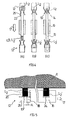
- Fig. 4b is a explained in more detail in Fig. 5 intermediate position shown, in which the Contact pins L1 to L3 already in contact with the relevant connection element 12th are the bridging parts 15 but over an extension 18 also in contact stand with the connection elements.
- Fig. 4c are only the bottom of the electricity meter 1 protruding contact pins in connection with the connecting elements 12.
- At one end of the bridging parts 15 is at 22 an air and creepage distance to the respective connection elements 12 formed.
- the springs consist of an inner part 23 made of copper and a spring effect reinforcing outer part 25 made of steel. From the connection elements 12 can lead away with these connected power cable or they may form part of a preformed solid conductor part, e.g. to a terminal strip leads.
- Fig. 6 illustrates again with reference to other connection elements, the various Connection phases.
- the spring legs (14a, 15a) parallel to the support plate 7, as the spring legs 13 and 14 of the connecting elements 12 or vertically to go to.
- two Contact bumps 26 and 27 are provided. Between the contact humps could Spring legs 14a and 15a be slotted for the above reason.
- Fig. 6a shows the position of bridging parts 15a in the absence of the electricity meter.
- the electricity meter is placed on the support plate 1, but still not moved.
- Fig. 6c shows the intermediate position, in which the bridging parts 15a, the connection elements 12a still short circuit.
- Fig. 6d is the counter connected and between an end of the bridging parts 15a and the relevant connection element 12a an air and creepage distance 22a is formed.
- the bridging parts 15a are retracted so far, that at 34 an isolating distance is formed, the length of the adjacent Mains voltage is sufficient.
- the bridging parts 15a upon delivery of a device using counter and Distribution cabinet. In this position, the bridging parts are not over one Locked device shown with a through one of the openings 10th solve solved special tool. For example, through the tool a the connecting parts in the position shown holding barb form-fitting holder be solved.
- Fig. 8 shows a meter and distribution cabinet, on which electricity meter in the foregoing described manner can be connected.
- the small width of the Connection device allows such a small width of the meter body that on conventional Counter places two counters 29 and 30 can be accommodated. In between there is even room for under the meter support plate arranged Cable channels, as indicated at 31. Above the small in their dimensions Counter 29.30 has room for a separate box 32 in which the utility company Control devices u. Like. Can place.
- the counter support plate can accommodate conventional, attachable by counter cross Be prepared for counters, with a slot for attachment between the counters a horizontal counter cross leg and an opening 33 for cable entry would be provided.
- a definitive counter cross leg can be within the field 32 for attaching a device-bearing DIN rail or directly to the Use attachment of equipment.
- the device could be part of the adapter, in the content next to the DE 100 52 998 A1 German patent application 102 61 204.6 included here described and which can be attached to conventional meter locations, to record power meters of the type described.
- This adapter could be above of the meter, a utility usable by the utility the field 32 have.
- the invention solution provides space, among the counters between the hooks 4 and Pins L3, L3 'still another cable channel for the connection of additional equipment and / or to form the meter of leading cables.
- the electricity meter and the support plate are not shown in FIG. 9.
- the electricity meter can be moved on the support plate in a guide, so that the contact pins 101,101 'according to arrow 102 can reciprocate.
- connection elements 103 or 103 ' which in the relevant embodiment approximately U-shaped bent spring 104 or 104 'of a spring material and a connecting conductor 105 or 105 'made of copper to ensure adequate Have contact.
- the connecting conductor 105 or 105 ' is integrally into a solid conductor piece 106 or 106 'over, wherein connecting conductor and conductor piece of a single, curved Sheet metal strips are formed.
- the bent conductor pieces 106, 106 'each have a flat pressure piece 107, which is guided in a socket 108 of a terminal block 109 and by rotation of a End portion of the conductor pieces 106,107 is formed. Dashed lines at 125 indicate that the conductor pieces 106 also located at one above the connection elements 103 another terminal block, in particular a main conductor terminal being able to lead.
- plug approaches 116 may be formed, which protrude from the terminal block 109 and with another Terminal block are connectable.
- the device shown is part of an adapter for a Electric meter is, and the adapter with the meter connected to a meter plug terminal on one provided for the inclusion of another electricity meter Support plate to be coupled.
- the conductor pieces become passed through the terminal block 109 or there are other facilities for Guiding and holding the conductor pieces provided.
- the conductor piece strips are used to form the plug attachment 116 forming cut surfaces 110 and 111 at their longitudinal edges cut in and partially through the opposite incisions separated Blechend Publishede rolled around the strip longitudinal axis, wherein edge surfaces the Blechend Publishede at 112 abut.
- the reference numeral 113 indicates connectors that connect the leads 105,105 'electrically connect together in the absence of a power meter.
- the preferably formed by a copper sheet strip connectors 113th each have an edge recess 114 for the engagement of the respective contact pin 101 ', so that the connecting elements 113 according to arrow 102 by displacement of the electricity meter are reciprocable.
- Support and guide parts for the springs 104, the conductor pieces 106 and the connecting pieces 113 are not shown in FIG. 9. Such parts may e.g. in one piece with be connected to the above-mentioned support plate.
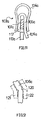
- connection element 103a differs for a connection element 103a from the connecting elements 103 shown above in that a integral with a conductor piece 106a connected terminal conductor 105a U-shaped with a further leg 117 is formed, so that a contact pin 101 a on both sides abuts against the connection conductor.
- a U-shaped spring 104a lies with both of them Legs against the outer sides of the legs of the U-shaped connecting conductor 105 a at.
- a fragmentary section of a conductor piece 106c shown in FIG. 12 points at a bending point opposing notches 120, which allow for such flexibility lead the conductor piece that tolerance deviations of the conductor piece and possibly of the conductor piece holding, e.g. holding webs 121 connected to the carrier plate and 122 can be compensated.
Landscapes
- Engineering & Computer Science (AREA)
- Power Engineering (AREA)
- Physics & Mathematics (AREA)
- General Physics & Mathematics (AREA)
- Measuring Leads Or Probes (AREA)
- Connections Arranged To Contact A Plurality Of Conductors (AREA)
Priority Applications (1)
| Application Number | Priority Date | Filing Date | Title |
|---|---|---|---|
| EP12187511.6A EP2544012B1 (fr) | 2003-03-27 | 2004-03-25 | Système d' un compteur d'électricité et d'un dispositif de connexion pour ledit compteur d'électricité |
Applications Claiming Priority (4)
| Application Number | Priority Date | Filing Date | Title |
|---|---|---|---|
| DE2003113999 DE10313999A1 (de) | 2003-03-27 | 2003-03-27 | Anschlussvorrichtung für einen Stromzähler |
| DE10313999 | 2003-03-27 | ||
| DE2003123161 DE10323161A1 (de) | 2003-03-27 | 2003-05-16 | Anschlussvorrichtung für einen Stromzähler |
| DE10323161 | 2003-05-16 |
Related Child Applications (2)
| Application Number | Title | Priority Date | Filing Date |
|---|---|---|---|
| EP12187511.6A Division-Into EP2544012B1 (fr) | 2003-03-27 | 2004-03-25 | Système d' un compteur d'électricité et d'un dispositif de connexion pour ledit compteur d'électricité |
| EP12187511.6A Division EP2544012B1 (fr) | 2003-03-27 | 2004-03-25 | Système d' un compteur d'électricité et d'un dispositif de connexion pour ledit compteur d'électricité |
Publications (2)
| Publication Number | Publication Date |
|---|---|
| EP1462808A1 true EP1462808A1 (fr) | 2004-09-29 |
| EP1462808B1 EP1462808B1 (fr) | 2016-08-24 |
Family
ID=32826231
Family Applications (2)
| Application Number | Title | Priority Date | Filing Date |
|---|---|---|---|
| EP04007202.7A Expired - Lifetime EP1462808B1 (fr) | 2003-03-27 | 2004-03-25 | Dispositif de connexion pour un compteur d'électricité |
| EP12187511.6A Expired - Lifetime EP2544012B1 (fr) | 2003-03-27 | 2004-03-25 | Système d' un compteur d'électricité et d'un dispositif de connexion pour ledit compteur d'électricité |
Family Applications After (1)
| Application Number | Title | Priority Date | Filing Date |
|---|---|---|---|
| EP12187511.6A Expired - Lifetime EP2544012B1 (fr) | 2003-03-27 | 2004-03-25 | Système d' un compteur d'électricité et d'un dispositif de connexion pour ledit compteur d'électricité |
Country Status (3)
| Country | Link |
|---|---|
| EP (2) | EP1462808B1 (fr) |
| DE (1) | DE10323161A1 (fr) |
| PL (1) | PL1462808T3 (fr) |
Cited By (5)
| Publication number | Priority date | Publication date | Assignee | Title |
|---|---|---|---|---|
| EP1569002A1 (fr) * | 2004-02-27 | 2005-08-31 | ABB PATENT GmbH | Système d'un compteur d'électricité |
| EP1657555A1 (fr) * | 2004-11-10 | 2006-05-17 | ABB PATENT GmbH | Support pour connecter un compteur électrique |
| EP2325949A1 (fr) * | 2009-11-19 | 2011-05-25 | Hager Electro GmbH & Co. KG | Dispositif de connexuion pour un compteur électronique d'électricité |
| EP2315041A3 (fr) * | 2009-10-24 | 2011-06-29 | Hager Electro GmbH & Co. KG | Compteur d'électricité électronique |
| EP2267464A3 (fr) * | 2009-06-25 | 2017-03-08 | Hager Electro GmbH & Co. KG | Elément d'enjambement de conducteurs électriques agencés à intervalle les uns vers les autres |
Families Citing this family (2)
| Publication number | Priority date | Publication date | Assignee | Title |
|---|---|---|---|---|
| DE102004028223A1 (de) * | 2004-01-20 | 2005-08-04 | Abb Patent Gmbh | Stromzähleranordnung |
| DE102008035720A1 (de) * | 2008-07-28 | 2010-02-04 | Hager Electro Gmbh & Co. Kg | Anschlussvorrichtung für einen Stromzähler |
Citations (6)
| Publication number | Priority date | Publication date | Assignee | Title |
|---|---|---|---|---|
| DE669192C (de) * | 1935-01-11 | 1938-12-19 | Siemens Schuckertwerke Akt Ges | Zaehleranschluss |
| US3369088A (en) | 1966-07-27 | 1968-02-13 | Murray Mfg Corp | Electric meter by-pass arrangement |
| US4388670A (en) * | 1981-05-18 | 1983-06-14 | Siemens-Allis, Inc. | Bypass and meter release for watthour meter socket |
| US6059605A (en) * | 1997-10-30 | 2000-05-09 | Ekstrom Industries, Inc. | Watthour meter socket adapter |
| DE10052998A1 (de) | 2000-10-24 | 2002-05-02 | Hager Electro Gmbh | Aufnahmeplattform für eine Stromzählereinheit |
| DE10054771A1 (de) * | 2000-10-23 | 2002-05-02 | Geyer Ag | Befestigungs- und Kontaktiereinrichtung |
Family Cites Families (3)
| Publication number | Priority date | Publication date | Assignee | Title |
|---|---|---|---|---|
| DE20216393U1 (de) * | 2002-10-24 | 2003-01-02 | Geyer AG, 90441 Nürnberg | Befestigungs- und Kontaktiereinrichtung für einen elektronischen Elektrizitätszähler |
| DE10261206B4 (de) | 2002-12-20 | 2007-04-26 | Hager Electro Gmbh | Adapter zur Ankopplung eines Stromzählers an eine ein Zählerkreuz aufweisende Trägerplattform |
| DE10261204A1 (de) | 2002-12-20 | 2004-07-08 | Zoz Gmbh | Verfahren zur Dekontamination bzw. Detoxifizierung von Umweltgiften z. B. Dioxiden, Dibenzofuranen und Beiprodukten (Congenere) oder dergleichen |
-
2003
- 2003-05-16 DE DE2003123161 patent/DE10323161A1/de not_active Withdrawn
-
2004
- 2004-03-25 EP EP04007202.7A patent/EP1462808B1/fr not_active Expired - Lifetime
- 2004-03-25 PL PL04007202T patent/PL1462808T3/pl unknown
- 2004-03-25 EP EP12187511.6A patent/EP2544012B1/fr not_active Expired - Lifetime
Patent Citations (6)
| Publication number | Priority date | Publication date | Assignee | Title |
|---|---|---|---|---|
| DE669192C (de) * | 1935-01-11 | 1938-12-19 | Siemens Schuckertwerke Akt Ges | Zaehleranschluss |
| US3369088A (en) | 1966-07-27 | 1968-02-13 | Murray Mfg Corp | Electric meter by-pass arrangement |
| US4388670A (en) * | 1981-05-18 | 1983-06-14 | Siemens-Allis, Inc. | Bypass and meter release for watthour meter socket |
| US6059605A (en) * | 1997-10-30 | 2000-05-09 | Ekstrom Industries, Inc. | Watthour meter socket adapter |
| DE10054771A1 (de) * | 2000-10-23 | 2002-05-02 | Geyer Ag | Befestigungs- und Kontaktiereinrichtung |
| DE10052998A1 (de) | 2000-10-24 | 2002-05-02 | Hager Electro Gmbh | Aufnahmeplattform für eine Stromzählereinheit |
Cited By (5)
| Publication number | Priority date | Publication date | Assignee | Title |
|---|---|---|---|---|
| EP1569002A1 (fr) * | 2004-02-27 | 2005-08-31 | ABB PATENT GmbH | Système d'un compteur d'électricité |
| EP1657555A1 (fr) * | 2004-11-10 | 2006-05-17 | ABB PATENT GmbH | Support pour connecter un compteur électrique |
| EP2267464A3 (fr) * | 2009-06-25 | 2017-03-08 | Hager Electro GmbH & Co. KG | Elément d'enjambement de conducteurs électriques agencés à intervalle les uns vers les autres |
| EP2315041A3 (fr) * | 2009-10-24 | 2011-06-29 | Hager Electro GmbH & Co. KG | Compteur d'électricité électronique |
| EP2325949A1 (fr) * | 2009-11-19 | 2011-05-25 | Hager Electro GmbH & Co. KG | Dispositif de connexuion pour un compteur électronique d'électricité |
Also Published As
| Publication number | Publication date |
|---|---|
| EP2544012A1 (fr) | 2013-01-09 |
| EP1462808B1 (fr) | 2016-08-24 |
| PL1462808T3 (pl) | 2017-02-28 |
| EP2544012B1 (fr) | 2016-05-04 |
| DE10323161A1 (de) | 2004-12-23 |
Similar Documents
| Publication | Publication Date | Title |
|---|---|---|
| EP3284139B1 (fr) | Borne à ressort | |
| DE602005000149T2 (de) | Anschlussanordnung eines elektrischen Gerätes | |
| DE3239708C2 (fr) | ||
| DE19817925B4 (de) | Federkraftklemmanschluß für elektrische Leiter | |
| DE10351289B4 (de) | Steckbrücke für elektrische Anschluß- und/oder Verbindungsklemmen | |
| DE10216913A1 (de) | Anschlussleiste | |
| EP2715871B1 (fr) | Dispositif de contrôle et de connexion | |
| DE10313999A1 (de) | Anschlussvorrichtung für einen Stromzähler | |
| EP2457289A1 (fr) | Dispositif de connexion et bloc de jonction à option connectable | |
| EP2915215A1 (fr) | Ensemble de modules en série pourvu d'un système de bus d'énergie | |
| EP1811604A2 (fr) | Barette à bornes électriques | |
| DE102007053535A1 (de) | Verbindungsmodul und Schaltgerät mit einem Verbindungsmodul | |
| DE19615597B4 (de) | Vorrichtung zum Kontaktieren der Leiteradern von mehreren bandförmig verlaufenden bielektrischen Leitungen mit den Leiteradern von elektrischen Anschlußleitungen eines elektrischen Verbrauchers, insbesondere den Leuchten einer Schienenleuchte | |
| DE102010010259A1 (de) | Steckverbinder und Gegensteckverbinder | |
| DE69019187T2 (de) | Elektrischer Mehrleiterkabelverbinder. | |
| EP2544012B1 (fr) | Système d' un compteur d'électricité et d'un dispositif de connexion pour ledit compteur d'électricité | |
| DE102004025605A1 (de) | Anschlussvorrichtung für einen Stromzähler | |
| DE202012005124U1 (de) | Vorrichtung für die Kontaktierung eines LED-Bandes sowie Vorrichtung für die elektrisch leitende Verbindung mindestens zweier LED-Bänder | |
| EP2278665B1 (fr) | Pièce de raccordement destinée à la fabrication d'un contact électrique | |
| EP0310832A2 (fr) | Support de broches de contact multiples pour des installations basse tension | |
| DE8136054U1 (de) | Anschlußklemme | |
| DE2829721C3 (de) | Mosaikbaustein für Schalt- und Meldewarten | |
| DE102017110060B4 (de) | Verfahren zum Herstellen einer Anordnung und Anordnung mit einer Stromschiene für eine Anschlussklemme zum Kontaktieren mehrerer elektrischer Leiter und elektrische Anschlussklemme | |
| DE2802643A1 (de) | Steckverbinder | |
| EP1544627B1 (fr) | Dispositif de raccordement pour un compteur d'électricité |
Legal Events
| Date | Code | Title | Description |
|---|---|---|---|
| PUAI | Public reference made under article 153(3) epc to a published international application that has entered the european phase |
Free format text: ORIGINAL CODE: 0009012 |
|
| AK | Designated contracting states |
Kind code of ref document: A1 Designated state(s): AT BE BG CH CY CZ DE DK EE ES FI FR GB GR HU IE IT LI LU MC NL PL PT RO SE SI SK TR |
|
| AX | Request for extension of the european patent |
Extension state: AL LT LV MK |
|
| 17P | Request for examination filed |
Effective date: 20050112 |
|
| AKX | Designation fees paid |
Designated state(s): AT BE BG CH CY CZ DE DK EE ES FI FR GB GR HU IE IT LI LU MC NL PL PT RO SE SI SK TR |
|
| 17Q | First examination report despatched |
Effective date: 20100927 |
|
| RAP1 | Party data changed (applicant data changed or rights of an application transferred) |
Owner name: HAGER ELECTRO GMBH & CO. KG |
|
| REG | Reference to a national code |
Ref country code: DE Ref legal event code: R079 Ref document number: 502004015286 Country of ref document: DE Free format text: PREVIOUS MAIN CLASS: G01R0011040000 Ipc: G01R0022060000 |
|
| GRAP | Despatch of communication of intention to grant a patent |
Free format text: ORIGINAL CODE: EPIDOSNIGR1 |
|
| INTG | Intention to grant announced |
Effective date: 20160311 |
|
| RIC1 | Information provided on ipc code assigned before grant |
Ipc: G01R 22/06 20060101AFI20160229BHEP |
|
| RIN1 | Information on inventor provided before grant (corrected) |
Inventor name: CLEMENS, GUNTRAM Inventor name: ZIMMERMANN, MANFRED Inventor name: KELAIDITIS, KONSTANTIN Inventor name: ZIMMERMANN, MICHAEL |
|
| GRAS | Grant fee paid |
Free format text: ORIGINAL CODE: EPIDOSNIGR3 |
|
| GRAA | (expected) grant |
Free format text: ORIGINAL CODE: 0009210 |
|
| AK | Designated contracting states |
Kind code of ref document: B1 Designated state(s): AT BE BG CH CY CZ DE DK EE ES FI FR GB GR HU IE IT LI LU MC NL PL PT RO SE SI SK TR |
|
| REG | Reference to a national code |
Ref country code: GB Ref legal event code: FG4D Free format text: NOT ENGLISH |
|
| REG | Reference to a national code |
Ref country code: CH Ref legal event code: EP |
|
| REG | Reference to a national code |
Ref country code: AT Ref legal event code: REF Ref document number: 823555 Country of ref document: AT Kind code of ref document: T Effective date: 20160915 |
|
| REG | Reference to a national code |
Ref country code: IE Ref legal event code: FG4D Free format text: LANGUAGE OF EP DOCUMENT: GERMAN |
|
| REG | Reference to a national code |
Ref country code: DE Ref legal event code: R096 Ref document number: 502004015286 Country of ref document: DE |
|
| REG | Reference to a national code |
Ref country code: CH Ref legal event code: NV Representative=s name: ALDO ROEMPLER PATENTANWALT, CH |
|
| REG | Reference to a national code |
Ref country code: NL Ref legal event code: MP Effective date: 20160824 |
|
| PG25 | Lapsed in a contracting state [announced via postgrant information from national office to epo] |
Ref country code: IT Free format text: LAPSE BECAUSE OF FAILURE TO SUBMIT A TRANSLATION OF THE DESCRIPTION OR TO PAY THE FEE WITHIN THE PRESCRIBED TIME-LIMIT Effective date: 20160824 Ref country code: FI Free format text: LAPSE BECAUSE OF FAILURE TO SUBMIT A TRANSLATION OF THE DESCRIPTION OR TO PAY THE FEE WITHIN THE PRESCRIBED TIME-LIMIT Effective date: 20160824 Ref country code: NL Free format text: LAPSE BECAUSE OF FAILURE TO SUBMIT A TRANSLATION OF THE DESCRIPTION OR TO PAY THE FEE WITHIN THE PRESCRIBED TIME-LIMIT Effective date: 20160824 |
|
| PG25 | Lapsed in a contracting state [announced via postgrant information from national office to epo] |
Ref country code: SE Free format text: LAPSE BECAUSE OF FAILURE TO SUBMIT A TRANSLATION OF THE DESCRIPTION OR TO PAY THE FEE WITHIN THE PRESCRIBED TIME-LIMIT Effective date: 20160824 Ref country code: ES Free format text: LAPSE BECAUSE OF FAILURE TO SUBMIT A TRANSLATION OF THE DESCRIPTION OR TO PAY THE FEE WITHIN THE PRESCRIBED TIME-LIMIT Effective date: 20160824 Ref country code: GR Free format text: LAPSE BECAUSE OF FAILURE TO SUBMIT A TRANSLATION OF THE DESCRIPTION OR TO PAY THE FEE WITHIN THE PRESCRIBED TIME-LIMIT Effective date: 20161125 Ref country code: PT Free format text: LAPSE BECAUSE OF FAILURE TO SUBMIT A TRANSLATION OF THE DESCRIPTION OR TO PAY THE FEE WITHIN THE PRESCRIBED TIME-LIMIT Effective date: 20161226 |
|
| PG25 | Lapsed in a contracting state [announced via postgrant information from national office to epo] |
Ref country code: EE Free format text: LAPSE BECAUSE OF FAILURE TO SUBMIT A TRANSLATION OF THE DESCRIPTION OR TO PAY THE FEE WITHIN THE PRESCRIBED TIME-LIMIT Effective date: 20160824 Ref country code: RO Free format text: LAPSE BECAUSE OF FAILURE TO SUBMIT A TRANSLATION OF THE DESCRIPTION OR TO PAY THE FEE WITHIN THE PRESCRIBED TIME-LIMIT Effective date: 20160824 |
|
| REG | Reference to a national code |
Ref country code: DE Ref legal event code: R097 Ref document number: 502004015286 Country of ref document: DE |
|
| PG25 | Lapsed in a contracting state [announced via postgrant information from national office to epo] |
Ref country code: BG Free format text: LAPSE BECAUSE OF FAILURE TO SUBMIT A TRANSLATION OF THE DESCRIPTION OR TO PAY THE FEE WITHIN THE PRESCRIBED TIME-LIMIT Effective date: 20161124 Ref country code: CZ Free format text: LAPSE BECAUSE OF FAILURE TO SUBMIT A TRANSLATION OF THE DESCRIPTION OR TO PAY THE FEE WITHIN THE PRESCRIBED TIME-LIMIT Effective date: 20160824 Ref country code: SK Free format text: LAPSE BECAUSE OF FAILURE TO SUBMIT A TRANSLATION OF THE DESCRIPTION OR TO PAY THE FEE WITHIN THE PRESCRIBED TIME-LIMIT Effective date: 20160824 Ref country code: DK Free format text: LAPSE BECAUSE OF FAILURE TO SUBMIT A TRANSLATION OF THE DESCRIPTION OR TO PAY THE FEE WITHIN THE PRESCRIBED TIME-LIMIT Effective date: 20160824 |
|
| PGFP | Annual fee paid to national office [announced via postgrant information from national office to epo] |
Ref country code: PL Payment date: 20170303 Year of fee payment: 14 |
|
| PLBE | No opposition filed within time limit |
Free format text: ORIGINAL CODE: 0009261 |
|
| STAA | Information on the status of an ep patent application or granted ep patent |
Free format text: STATUS: NO OPPOSITION FILED WITHIN TIME LIMIT |
|
| 26N | No opposition filed |
Effective date: 20170526 |
|
| PG25 | Lapsed in a contracting state [announced via postgrant information from national office to epo] |
Ref country code: SI Free format text: LAPSE BECAUSE OF FAILURE TO SUBMIT A TRANSLATION OF THE DESCRIPTION OR TO PAY THE FEE WITHIN THE PRESCRIBED TIME-LIMIT Effective date: 20160824 |
|
| GBPC | Gb: european patent ceased through non-payment of renewal fee |
Effective date: 20170325 |
|
| PG25 | Lapsed in a contracting state [announced via postgrant information from national office to epo] |
Ref country code: MC Free format text: LAPSE BECAUSE OF FAILURE TO SUBMIT A TRANSLATION OF THE DESCRIPTION OR TO PAY THE FEE WITHIN THE PRESCRIBED TIME-LIMIT Effective date: 20160824 |
|
| REG | Reference to a national code |
Ref country code: IE Ref legal event code: MM4A |
|
| REG | Reference to a national code |
Ref country code: FR Ref legal event code: ST Effective date: 20171130 |
|
| PG25 | Lapsed in a contracting state [announced via postgrant information from national office to epo] |
Ref country code: LU Free format text: LAPSE BECAUSE OF NON-PAYMENT OF DUE FEES Effective date: 20170325 Ref country code: FR Free format text: LAPSE BECAUSE OF NON-PAYMENT OF DUE FEES Effective date: 20170331 |
|
| PG25 | Lapsed in a contracting state [announced via postgrant information from national office to epo] |
Ref country code: GB Free format text: LAPSE BECAUSE OF NON-PAYMENT OF DUE FEES Effective date: 20170325 Ref country code: IE Free format text: LAPSE BECAUSE OF NON-PAYMENT OF DUE FEES Effective date: 20170325 |
|
| REG | Reference to a national code |
Ref country code: BE Ref legal event code: MM Effective date: 20170331 |
|
| PG25 | Lapsed in a contracting state [announced via postgrant information from national office to epo] |
Ref country code: BE Free format text: LAPSE BECAUSE OF NON-PAYMENT OF DUE FEES Effective date: 20170331 |
|
| PGFP | Annual fee paid to national office [announced via postgrant information from national office to epo] |
Ref country code: AT Payment date: 20190305 Year of fee payment: 16 |
|
| PG25 | Lapsed in a contracting state [announced via postgrant information from national office to epo] |
Ref country code: HU Free format text: LAPSE BECAUSE OF FAILURE TO SUBMIT A TRANSLATION OF THE DESCRIPTION OR TO PAY THE FEE WITHIN THE PRESCRIBED TIME-LIMIT; INVALID AB INITIO Effective date: 20040325 |
|
| PG25 | Lapsed in a contracting state [announced via postgrant information from national office to epo] |
Ref country code: PL Free format text: LAPSE BECAUSE OF NON-PAYMENT OF DUE FEES Effective date: 20180325 |
|
| PGFP | Annual fee paid to national office [announced via postgrant information from national office to epo] |
Ref country code: CH Payment date: 20190404 Year of fee payment: 16 |
|
| PG25 | Lapsed in a contracting state [announced via postgrant information from national office to epo] |
Ref country code: CY Free format text: LAPSE BECAUSE OF NON-PAYMENT OF DUE FEES Effective date: 20160824 |
|
| PG25 | Lapsed in a contracting state [announced via postgrant information from national office to epo] |
Ref country code: TR Free format text: LAPSE BECAUSE OF FAILURE TO SUBMIT A TRANSLATION OF THE DESCRIPTION OR TO PAY THE FEE WITHIN THE PRESCRIBED TIME-LIMIT Effective date: 20160824 |
|
| REG | Reference to a national code |
Ref country code: CH Ref legal event code: PL |
|
| REG | Reference to a national code |
Ref country code: AT Ref legal event code: MM01 Ref document number: 823555 Country of ref document: AT Kind code of ref document: T Effective date: 20200325 |
|
| PG25 | Lapsed in a contracting state [announced via postgrant information from national office to epo] |
Ref country code: LI Free format text: LAPSE BECAUSE OF NON-PAYMENT OF DUE FEES Effective date: 20200331 Ref country code: CH Free format text: LAPSE BECAUSE OF NON-PAYMENT OF DUE FEES Effective date: 20200331 Ref country code: AT Free format text: LAPSE BECAUSE OF NON-PAYMENT OF DUE FEES Effective date: 20200325 |
|
| PGFP | Annual fee paid to national office [announced via postgrant information from national office to epo] |
Ref country code: DE Payment date: 20230329 Year of fee payment: 20 |
|
| REG | Reference to a national code |
Ref country code: DE Ref legal event code: R071 Ref document number: 502004015286 Country of ref document: DE |