EP1463146A1 - Kostengünstige Antenne aus Harz mit leitfähigen Zusätzen und mit Drahtinnenleiter und Herstellungsverfahren - Google Patents
Kostengünstige Antenne aus Harz mit leitfähigen Zusätzen und mit Drahtinnenleiter und Herstellungsverfahren Download PDFInfo
- Publication number
- EP1463146A1 EP1463146A1 EP04392010A EP04392010A EP1463146A1 EP 1463146 A1 EP1463146 A1 EP 1463146A1 EP 04392010 A EP04392010 A EP 04392010A EP 04392010 A EP04392010 A EP 04392010A EP 1463146 A1 EP1463146 A1 EP 1463146A1
- Authority
- EP
- European Patent Office
- Prior art keywords
- antenna
- fibers
- micron
- micron conductor
- loaded resin
- Prior art date
- Legal status (The legal status is an assumption and is not a legal conclusion. Google has not performed a legal analysis and makes no representation as to the accuracy of the status listed.)
- Withdrawn
Links
Images

Classifications
-
- A—HUMAN NECESSITIES
- A01—AGRICULTURE; FORESTRY; ANIMAL HUSBANDRY; HUNTING; TRAPPING; FISHING
- A01M—CATCHING, TRAPPING OR SCARING OF ANIMALS; APPARATUS FOR THE DESTRUCTION OF NOXIOUS ANIMALS OR NOXIOUS PLANTS
- A01M7/00—Special adaptations or arrangements of liquid-spraying apparatus for purposes covered by this subclass
- A01M7/0025—Mechanical sprayers
- A01M7/0032—Pressure sprayers
- A01M7/0046—Hand-operated sprayers
-
- H—ELECTRICITY
- H01—ELECTRIC ELEMENTS
- H01Q—ANTENNAS, i.e. RADIO AERIALS
- H01Q1/00—Details of, or arrangements associated with, antennas
- H01Q1/40—Radiating elements coated with or embedded in protective material
-
- B—PERFORMING OPERATIONS; TRANSPORTING
- B05—SPRAYING OR ATOMISING IN GENERAL; APPLYING FLUENT MATERIALS TO SURFACES, IN GENERAL
- B05B—SPRAYING APPARATUS; ATOMISING APPARATUS; NOZZLES
- B05B11/00—Single-unit hand-held apparatus in which flow of contents is produced by the muscular force of the operator at the moment of use
- B05B11/01—Single-unit hand-held apparatus in which flow of contents is produced by the muscular force of the operator at the moment of use characterised by the means producing the flow
- B05B11/10—Pump arrangements for transferring the contents from the container to a pump chamber by a sucking effect and forcing the contents out through the dispensing nozzle
- B05B11/1001—Piston pumps
- B05B11/1002—Piston pumps the direction of the pressure stroke being substantially perpendicular to the major axis of the container
-
- B—PERFORMING OPERATIONS; TRANSPORTING
- B05—SPRAYING OR ATOMISING IN GENERAL; APPLYING FLUENT MATERIALS TO SURFACES, IN GENERAL
- B05B—SPRAYING APPARATUS; ATOMISING APPARATUS; NOZZLES
- B05B11/00—Single-unit hand-held apparatus in which flow of contents is produced by the muscular force of the operator at the moment of use
- B05B11/01—Single-unit hand-held apparatus in which flow of contents is produced by the muscular force of the operator at the moment of use characterised by the means producing the flow
- B05B11/10—Pump arrangements for transferring the contents from the container to a pump chamber by a sucking effect and forcing the contents out through the dispensing nozzle
- B05B11/1042—Components or details
-
- B—PERFORMING OPERATIONS; TRANSPORTING
- B05—SPRAYING OR ATOMISING IN GENERAL; APPLYING FLUENT MATERIALS TO SURFACES, IN GENERAL
- B05B—SPRAYING APPARATUS; ATOMISING APPARATUS; NOZZLES
- B05B9/00—Spraying apparatus for discharge of liquids or other fluent material, without essentially mixing with gas or vapour
- B05B9/03—Spraying apparatus for discharge of liquids or other fluent material, without essentially mixing with gas or vapour characterised by means for supplying liquid or other fluent material
- B05B9/04—Spraying apparatus for discharge of liquids or other fluent material, without essentially mixing with gas or vapour characterised by means for supplying liquid or other fluent material with pressurised or compressible container; with pump
- B05B9/08—Apparatus to be carried on or by a person, e.g. of knapsack type
- B05B9/0805—Apparatus to be carried on or by a person, e.g. of knapsack type comprising a pressurised or compressible container for liquid or other fluent material
- B05B9/0811—Apparatus to be carried on or by a person, e.g. of knapsack type comprising a pressurised or compressible container for liquid or other fluent material comprising air supplying means actuated by the operator to pressurise or compress the container
- B05B9/0816—Apparatus to be carried on or by a person, e.g. of knapsack type comprising a pressurised or compressible container for liquid or other fluent material comprising air supplying means actuated by the operator to pressurise or compress the container the air supplying means being a manually actuated air pump
-
- H—ELECTRICITY
- H01—ELECTRIC ELEMENTS
- H01Q—ANTENNAS, i.e. RADIO AERIALS
- H01Q1/00—Details of, or arrangements associated with, antennas
- H01Q1/36—Structural form of radiating elements, e.g. cone, spiral, umbrella; Particular materials used therewith
-
- H—ELECTRICITY
- H01—ELECTRIC ELEMENTS
- H01Q—ANTENNAS, i.e. RADIO AERIALS
- H01Q19/00—Combinations of primary active antenna elements and units with secondary devices, e.g. with quasi-optical devices, for giving the antenna a desired directional characteristic
- H01Q19/06—Combinations of primary active antenna elements and units with secondary devices, e.g. with quasi-optical devices, for giving the antenna a desired directional characteristic using refracting or diffracting devices, e.g. lens
- H01Q19/09—Combinations of primary active antenna elements and units with secondary devices, e.g. with quasi-optical devices, for giving the antenna a desired directional characteristic using refracting or diffracting devices, e.g. lens wherein the primary active element is coated with or embedded in a dielectric or magnetic material
-
- H—ELECTRICITY
- H01—ELECTRIC ELEMENTS
- H01Q—ANTENNAS, i.e. RADIO AERIALS
- H01Q9/00—Electrically-short antennas having dimensions not more than twice the operating wavelength and consisting of conductive active radiating elements
- H01Q9/04—Resonant antennas
- H01Q9/16—Resonant antennas with feed intermediate between the extremities of the antenna, e.g. centre-fed dipole
-
- H—ELECTRICITY
- H01—ELECTRIC ELEMENTS
- H01Q—ANTENNAS, i.e. RADIO AERIALS
- H01Q9/00—Electrically-short antennas having dimensions not more than twice the operating wavelength and consisting of conductive active radiating elements
- H01Q9/04—Resonant antennas
- H01Q9/16—Resonant antennas with feed intermediate between the extremities of the antenna, e.g. centre-fed dipole
- H01Q9/20—Two collinear substantially straight active elements; Substantially straight single active elements
-
- H—ELECTRICITY
- H01—ELECTRIC ELEMENTS
- H01Q—ANTENNAS, i.e. RADIO AERIALS
- H01Q9/00—Electrically-short antennas having dimensions not more than twice the operating wavelength and consisting of conductive active radiating elements
- H01Q9/04—Resonant antennas
- H01Q9/30—Resonant antennas with feed to end of elongated active element, e.g. unipole
- H01Q9/32—Vertical arrangement of element
Definitions
- This invention relates to antennas molded of conductive loaded resin-based materials comprising micron conductive powders or micron conductive fibers or in combination thereof, homogenized within a base resin when molded and having a conducting wire center or core. This yields a conductive part or material usable within the EMF or electronic spectrum(s).
- Antennas are an essential part of electronic communication systems that contain wireless links. Low cost antennas offer significant advantages for these systems.
- U.S. Pat. No. 5,771,027 to Marks et al. describes a composite antenna having a grid comprised of electrical conductors woven into the warp of a resin reinforced cloth forming one layer of a multi-layer laminate structure of an antenna.
- U.S. Pat. No. 6,486,853 B2 to Yoshinomoto et al. describe an antenna having a conductor wound on an insulating core body.
- the insulating core body can be formed using extrusion. There is no wire within the core body.
- U.S. Pat. No. 6,317,102 to Stambeck describes an antenna unit having an insulating jacket formed over a metallic core, such as a wire.
- U.S. Pat. No. 5,635,943 to Grunwell describes an antenna containing an antenna element having a conducting core surrounded by an insulating sheath.
- the conducting core can be a rigid rod or a wound wire semi-rigid coil.
- the insulating sheath can be a plastic film applied to the conduction core by extrusion.
- European patent application EP 1,233,426 entitled “LOW COST ANTENNAS USING CONDUCTIVE PLASTICS OR CONDUCTIVE COMPOSITES” discloses low cost antennas formed of conductive loaded resin based materials.
- Non published European patent application 2004392002.4 filed on 13. February 2004 entitled “Low Cost Antennas and Electromagnetic (EMF) Absorption in Electronic circuit Packages or Transceivers Using Conductive Loaded Resin-Based Materials” and assigned to the same assignee describe low cost antennas and electromagnetic absorption structures using conductive loaded resin-based materials.
- Antennas are an essential part of electronic circuitry, such as electronic communication systems that contain wireless links. Lowering the cost and improving the manufacturing capabilities for antennas provides an important advantage for these systems. Low cost molded antennas offer significant advantages for these systems not only from a fabrication standpoint, but also characteristics related to 2D, 3D, 4D, and 5D electrical characteristics, which include the physical advantages that can be achieved by the molding process of the actual parts and the polymer physics within the conductive networks formed within the molded part.
- the antennas are fabricated from molded conductive loaded resin-based materials, comprising micron conductive fibers, micron conductive powders, or in combination thereof, that are homogenized within a base resin host in a molding process and have a conducting wire center or core.
- the antennas are fabricated from molded conductive loaded resin-based materials comprising micron conductive fibers, micron conductive powders, or in combination thereof, that are homogenized within a base resin during the molding process and have a conducting wire center or core.
- the antennas are molding the antennas from conductive loaded resin-based materials around a conducting wire center.
- These conductive loaded resin-based materials are resins loaded with conductive materials to provide a resin-based material, which is a conductor rather than an insulator.
- the resins provide the structural material which; when loaded with micron conductive powders, micron conductive fibers, or any combination thereof, become composites which are conductors rather than insulators.
- the orientation of micron conductive fibers, micron conductive powders or in combination thereof, homogenized within the base resin may be tightly controlled in the molding process.
- Various desired electrical and EMF characteristics may be achieved during the molding and mix process.
- the conducting wire center can be any metal wire, such as copper, nickel, stainless steel, silver or the like.
- the wire can be single strand, multi strand, insulated, or non-insulated depending on desired electrical characteristics.
- These conductive loaded resin-based materials can be molded around a conducting wire center into any number of desired shapes and sizes using methods such as injection molding, over-molding, thermo-set, protrusion, extrusion, co-extrusion, compression, or the like.
- the conducting wire center can be single strand, multi-strand, insulated, or non-insulated wire.
- the method, wire gages, and/or wire types are chosen to achieve the desired electrical characteristics for an antenna.
- the conductive loaded resinbased material could also be a molded part, sheet, bar stock, or the like that may be cut, stamped, milled, laminated, vacuumed formed, or the like, formed around a conducting wire center, to provide the desired shape and size of this element or part.
- the characteristics of the antenna elements depend on the wire gages and/or types and on the composition of the conductive loaded resin-based materials, which can be adjusted and tightly controlled in achieving the desired characteristics of the molded material.
- This invention relates to antennas molded of conductive loaded resin-based materials comprising micron conductive powders, micron conductive fibers, or a combination thereof, homogenized within a base resin when molded and having a conducting wire center core.
- the conductive loaded resin-based materials of the invention are base resins loaded with conductive materials, which then makes any base resin a conductor rather than an insulator.
- the resins provide the structural integrity to the molded part.
- the micron conductive fibers, micron conductive powders, or a combination thereof, are homogenized within the resin during the molding process, providing the electrical continuity.
- the conductive loaded resin-based materials can be molded, extruded, coextruded, or the like to provide almost any desired shape or size.
- the molded conductive loaded resin-based materials can also be cut, stamped or vacuumed formed from injection molded, extruded, co-extruded, sheet or bar stock, over-molded, laminated, milled or the like to provide the desired antenna shape and size.
- the electrical characteristics of antennas fabricated using conductive loaded resin-based materials depend on the composition of the conductive loaded resin-based materials, of which the loading or doping parameters can be adjusted, to aid in achieving the desired structural, electrical or other physical characteristics of the material.
- the selected materials used to build the antennas are homogenized together using molding techniques and/or methods such as injection molding, over-molding, thermo-set, protrusion, extrusion, co-extrusion, or the like.
- Characteristics related to 2D, 3D, 4D, and 5D designs, molding and electrical characteristics include the physical and electrical advantages that can be achieved during the molding process of the actual parts and the polymer physics associated within the conductive networks within the molded part(s) or formed material(s).
- antennas significantly lowers the cost of materials and the design and manufacturing processes used to hold close tolerances, by forming these materials into desired shapes and sizes.
- the antennas can be manufactured into infinite shapes and sizes using conventional forming methods such as injection molding, overmolding, or extrusion, coextrusion, or the like.
- the conductive loaded resin-based materials when molded typically but not exclusively produce a desirable usable range of resistivity from between about 5 and 25 ohms per square, but other resistivities can be achieved by varying the doping parameters and/or resin selection(s).
- the conductive loaded resin-based materials comprise micron conductive powders, micron conductive fibers, or in any combination thereof, which are homogenized together within the base resin, during the molding process, yielding an easy to produce low cost, electrically conductive, close tolerance manufactured part or circuit.
- the micron conductive powders can be of carbons, graphites, amines or the like, and/or of metal powders such as nickel, copper, silver, or plated or the like. The use of carbons or other forms of powders such as graphite(s) etc.
- micron conductive fibers can be nickel plated carbon fiber, stainless steel fiber, copper fiber, silver fiber, or the like, or combinations thereof.
- the structural material is a material such as any polymer resin.
- Structural material can be, here given as examples and not as an exhaustive list, polymer resins produced by GE PLASTICS, Pittsfield, MA, a range of other plastics produced by GE PLASTICS, Pittsfield, MA, a range of other plastics produced by other manufacturers, silicones produced by GE SILICONES, Waterford, NY, or other flexible resin-based rubber compounds produced by other manufacturers.
- the resin-based structural material loaded with micron conductive powders, micron conductive fibers, or in combination thereof can be molded, using conventional molding methods such as injection molding or overmolding, extrusion, or co-extrusion to create desired shapes and sizes.
- the molded conductive loaded resin-based materials can also be stamped, cut or milled as desired to create the desired form factor(s) of the antennas.
- the doping composition and directionality associated with the micron conductors within the loaded base resins can affect the electrical and structural antenna characteristics, and can be precisely controlled by mold designs, gating and or protrusion design(s) and or during the molding process itself.
- a resin based sandwich laminate could also be fabricated with random or continuous webbed micron stainless steel fibers or other conductive fibers, forming a cloth like material.
- the webbed conductive fiber can be laminated or the like to materials such as Teflon, Polyesters, or any resin-based flexible or single strand material, which when discretely designed in fiber content(s), orientation(s) and shape(s), will produce a very highly conductive flexible cloth-like material.
- Such a cloth-like antenna could be embedded in a person's clothing as well as other resin materials such as rubber(s) or plastic(s).
- the fibers may have diameters of between about 3 and 12 microns, typically between about 8 and 12 microns or in the range of about 10 microns, with length(s) that can be seamless or overlapping.
- the conductive loaded resin-based material typically comprises a micron powder(s) of conductor particles, micron conductor fiber(s), or in combination thereof homogenized within a base resin host.
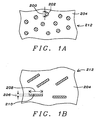
- Fig. 1A shows cross section view of an example of conductor loaded resin-based material 212 having a powder of conductor particles 202 in a base resin host 204. In this example the diameter 200 of the conductor particles 202 in the powder is between about 3 and 12 microns.
- Fig. 1B shows a cross section view of an example of conductor loaded resin-based material 212 having conductor fibers 210 in a base resin host 204.
- the conductor fibers 210 have a diameter 206 of between about 3 and 12 microns, typically in the range of 10 microns or between about 8 and 12 microns, and a length 208 of between about 2 and 14 millimeters.
- Fig. 1C shows a cross section view of an example of conductor loaded resin based material 212 having both a powder of conductor particles 202 and conductor fibers 210 in a base resin host 204.
- the diameter 200 of the conductor particles 202 in the powder is between about 3 and 12 microns and the conductor fibers 210 have a diameter 206 of between about 3 and 12 microns, typically in the range of 10 microns or between about 8 and 12 microns, and a length 208 of between about 2 and 14 millimeters.
- the conductors used for these conductor particles 202 or conductor fibers 210 can be stainless steel, nickel, copper, silver, or other suitable metals or conductive fibers, or combinations thereof. These conductor particles and/or fibers are homogenized within a base resin.
- the conductive loaded resin-based materials have a resistivity between about 5 and 25 ohms per square, but other resistivities can be achieved by varying the doping parameters and/or resin selection.
- the ratio of the weight of the conductor material, in this example the conductor particles 202 and/or conductor fibers 210, to the weight of the base resin host 204 is between about 0.20 and 0.40, and is preferably about 0.30.
- Stainless Steel Fiber of 8-11 micron in diameter and lengths of 4-6 mm with a fiber weight to base resin weight ratio of 0.30 will produce a very highly conductive parameter, efficient within any EMF spectrum.
- Electronic elements, antenna elements, or EMF absorbing elements formed from conductive loaded resin-based materials can be formed or molded in a number of different ways including injection molding, extrusion, co-extrusion, or chemically induced molding or forming.
- Fig. 2 shows a simplified schematic diagram of an injection mold showing a lower portion 230 and upper portion 231 of the mold. Raw' material conductive loaded blended resin-based material is injected into the mold cavity 237 through an injection opening 235 and the then homogenized conductive material cures by thermal reaction. The upper portion 231 and lower portion 230 of the mold are then separated or parted and the conductive antenna element is removed.
- Fig. 3 shows a simplified schematic diagram of an extruder for forming antenna elements using extrusion or co-extrusion.
- Raw material(s) conductive loaded resin-based material is placed in the hopper 239 of the extrusion or co-extrusion unit which feeds the material into the barrel 234.
- a piston, screw, press or other means, a screw 236 is shown in the example shown in Fig. 3, is then used to force the thermally molten or a chemically induced curing conductive loaded resin-based material through an extrusion opening 240, which shapes the thermally molten curing or chemically induced cured conductive loaded resin-based material to the desired shape.
- the conductive loaded resin-based material is then fully cured by chemical reaction or thermal reaction to a hardened or pliable state and is ready for use.
- the conductive loaded resin based material can be formed into fibers or textiles that are then woven or webbed into a conductive fabric.
- the conductive loaded resin-based material is formed in strands that can be woven as shown.
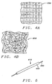
- Fig. 4A shows a conductive fabric 230 where the fibers are woven together in a two-dimensional weave of fibers or textiles.
- Fig. 4B shows a conductive fabric 232 where the fibers are formed in a webbed arrangement. In the webbed arrangement, one or more continuous strands of the conductive fiber are nested in a random fashion.
- the resulting conductive fabrics or textiles 230 see Fig. 4A, and 232, see Fig. 4B, can be made very thin, thick, rigid, flexible or in solid form(s).
- a conductive, but cloth-like, material can be formed using woven or webbed micron stainless steel fibers, or other micron conductive fibers. These woven or webbed conductive cloths could also be sandwich laminated to one or more layers of materials such as Polyester(s), Teflon(s), Kevlar(s) or any other desired resin-based material(s). This conductive fabric may then be cut into desired shapes and sizes.
- Figs. 5-11 for a description of antennas of this invention fabricated by molding conductive loaded resin based materials around a conducting wire center.
- the conducting wire center can be single strand wire, multi-strand wire, insulated wire, or non-insulated wire.
- Fig. 5 shows a perspective view of a segment of an antenna element 412 of conductive loaded resin-based material 402 molded around a conducting wire 400 center.
- the conducting wire 400 makes the conductive loaded resin-based material even more effective as antenna elements.
- the conductive loaded resin-based material, having a conducting wire center, antenna elements 412 can be molded by methods such as extrusion, co-extrusion, compression molding, injection molding, or the like.
- These conductive loaded resin-based material antenna elements 412 having a conducting wire center can also be fabricated by ultrasonic insertion of the conducting wire, insertion molding, or over-molding.
- the conducting wire center core enhances the performance of the antenna elements 412 and simplifies the connection of an antenna element to an electrical signal wire or to other antenna elements. As shown in Fig. 5 the center core wire 402 can protrude beyond the ends of the conductive loaded resin-based material 402.
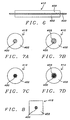
- Fig. 6 shows a longitudinal cross section view of the antenna element 412 shown in Fig. 5 showing the wire core 400 surrounded by the conductive loaded resin-based material 402.
- Fig. 6 shows a non-insulated single strand wire center 400; however, as shown in Figs. 7A-7D, the wire center 400 can be single strand, multi-strand, insulated, or non-insulated wire.
- Fig. 7A shows a transverse cross section view of the antenna element 412 shown in Fig. 5 for an antenna element having a circular cross section and a single strand, non-insulated wire center.
- Fig. 7B shows a transverse cross section view of the antenna element 412 shown in Fig.
- Fig. 7C shows a transverse cross section view of the antenna element 412 shown in Fig. 5 for an antenna element having a circular cross section and a multistrand, non-insulated wire center.
- Fig. 7D shows a transverse cross section view of the antenna element 412 shown in Fig. 5 for an antenna element having a circular cross section and a multi-strand, insulated wire center 400 with a layer of insulation 403 between the multi-strand wire center 400 and the conductor loaded resin-based material 402.
- the antenna elements formed in this manner can have any desired cross section shapes.
- Fig. 8 shows a transverse cross section view of the antenna element 412 shown in Fig. 5 for an antenna element having a rectangular cross section. Other cross section shapes can also be used.
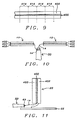
- the antenna elements can be fabricated by forming a long segment of conductive loaded resin-based material 402 having a conducting wire center 400. Individual antenna elements 414 can then be cut from the long segment.
- Fig. 10 shows a cross section view of a dipole antenna with a radiating or receiving antenna element 12 and a counterpoise antenna element 10 formed from conductive loaded resin-based materials 402 having a conducting wire center 400.
- the antenna comprises a radiating or receiving antenna element 12 and a counterpoise antenna element 10 each having a length and a cross section perpendicular to the length. Typically the length is greater than three multiplied by the square root of the cross sectional area.
- the center conductor 14 of a coaxial cable 50 is electrically connected to the conducting wire center 400 of the radiating or receiving antenna element 12.
- the shield 52 of the coaxial cable 50 is electrically connected to the conducting wire center 400 of the counterpoise antenna element 10.
- the length of the transmitting or receiving antenna element 12 is the same as the counterpoise antenna element 10 and is a multiple of a quarter wavelength of the optimum frequency of detection or transmission of the antenna.
- the impedance of the antenna at resonance should be very nearly equal to the impedance of the coaxial cable 50 to assure maximum power transfer between cable and antenna.
- Fig. 11 shows an example of a monopole antenna having a radiating or receiving antenna element 20 formed of conductive loaded resin-based material 402 having a conducting wire center 400.
- the radiating or receiving antenna element 20 is arranged perpendicular to a ground plane 22.
- the radiating or receiving antenna element 20 is electrically insulated from the ground plane 22.
- the ground plane 22 can be any suitable conductor and can be metal or conductive loaded resin-based material.
- the height of the radiating or receiving antenna element 20 is greater than three times the square root of the cross sectional area of the radiating or receiving antenna element 22.
- the center conductor 14 of a coaxial cable 50 is electrically connected to the conducting wire center 400 of the radiating or receiving antenna element 402.
- the shield 52 of the coaxial cable 50 is electrically connected to the ground plane 22.
- the length of the transmitting or receiving antenna element 402 is a multiple of a quarter wavelength of the optimum frequency of detection or transmission of the antenna.
- the impedance of the antenna at resonance should be very nearly equal to the impedance of the coaxial cable 50 to assure maximum power transfer between cable and antenna.
- Fig. 5, 6, and 8-11 show a single strand, non-insulated conducting wire center; single strand, insulated wire; multi-strand, noninsulated wire; and/or multi-strand insulated wire can also be used as the conducting wire center; as shown in Figs. 7A-7D.
Landscapes
- Engineering & Computer Science (AREA)
- Life Sciences & Earth Sciences (AREA)
- Mechanical Engineering (AREA)
- Insects & Arthropods (AREA)
- Pest Control & Pesticides (AREA)
- Wood Science & Technology (AREA)
- Zoology (AREA)
- Environmental Sciences (AREA)
- Details Of Aerials (AREA)
Applications Claiming Priority (2)
| Application Number | Priority Date | Filing Date | Title |
|---|---|---|---|
| US45697003P | 2003-03-24 | 2003-03-24 | |
| US456970 | 2003-03-24 |
Publications (1)
| Publication Number | Publication Date |
|---|---|
| EP1463146A1 true EP1463146A1 (de) | 2004-09-29 |
Family
ID=32927731
Family Applications (1)
| Application Number | Title | Priority Date | Filing Date |
|---|---|---|---|
| EP04392010A Withdrawn EP1463146A1 (de) | 2003-03-24 | 2004-03-23 | Kostengünstige Antenne aus Harz mit leitfähigen Zusätzen und mit Drahtinnenleiter und Herstellungsverfahren |
Country Status (5)
| Country | Link |
|---|---|
| EP (1) | EP1463146A1 (de) |
| JP (1) | JP2004297805A (de) |
| KR (1) | KR20040084789A (de) |
| CN (1) | CN1538555A (de) |
| CA (1) | CA2461969C (de) |
Cited By (4)
| Publication number | Priority date | Publication date | Assignee | Title |
|---|---|---|---|---|
| ITBS20120068A1 (it) * | 2012-04-19 | 2013-10-20 | Emme Esse S P A | Antenna a dipolo e procedimento per la sua fabbricazione |
| US8692722B2 (en) | 2011-02-01 | 2014-04-08 | Phoenix Contact Development and Manufacturing, Inc. | Wireless field device or wireless field device adapter with removable antenna module |
| EP2643884A4 (de) * | 2010-11-22 | 2014-07-09 | Chamtech Technologies Inc | Material zur weiterleitung, emission und/oder absorption elektromagnetischer strahlung |
| US10396451B2 (en) | 2010-11-22 | 2019-08-27 | Ncap Licensing, Llc | Techniques for patch antenna |
Families Citing this family (3)
| Publication number | Priority date | Publication date | Assignee | Title |
|---|---|---|---|---|
| JP2008236705A (ja) * | 2006-08-09 | 2008-10-02 | Daido Steel Co Ltd | 超広帯域通信用アンテナ |
| US8253643B2 (en) | 2007-06-07 | 2012-08-28 | Hitachi Metals Ltd. | Chip antenna and its production method, and antenna apparatus and communications apparatus comprising such chip antenna |
| US8907295B2 (en) * | 2012-08-01 | 2014-12-09 | Varian Semiconductor Equipment Associates, Inc. | Hybrid electrostatic lens with increased natural frequency |
Citations (7)
| Publication number | Priority date | Publication date | Assignee | Title |
|---|---|---|---|---|
| US4008477A (en) * | 1975-06-25 | 1977-02-15 | The United States Of America As Represented By The Secretary Of Commerce | Antenna with inherent filtering action |
| JPS5664502A (en) * | 1979-10-31 | 1981-06-01 | Toshiba Corp | Antenna |
| JPS57166702A (en) * | 1981-04-07 | 1982-10-14 | Kosugi Seiki Seisakusho:Kk | Antenna |
| US5554997A (en) * | 1989-08-29 | 1996-09-10 | Hughes Aircraft Company | Graphite composite structures exhibiting electrical conductivity |
| US6249261B1 (en) * | 2000-03-23 | 2001-06-19 | Southwest Research Institute | Polymer, composite, direction-finding antenna |
| US6356234B1 (en) * | 1996-06-12 | 2002-03-12 | R T Microwave Limited | Electrical circuit |
| EP1233426A2 (de) * | 2001-02-15 | 2002-08-21 | Integral Technologies, Inc. | Antennen mit elektrisch leitenden Kunststoffen oder elektrisch leitenden Zusammensetzungen |
-
2004
- 2004-03-23 EP EP04392010A patent/EP1463146A1/de not_active Withdrawn
- 2004-03-23 CA CA2461969A patent/CA2461969C/en not_active Expired - Fee Related
- 2004-03-24 KR KR1020040020145A patent/KR20040084789A/ko not_active Ceased
- 2004-03-24 CN CNA2004100326801A patent/CN1538555A/zh active Pending
- 2004-03-24 JP JP2004087200A patent/JP2004297805A/ja active Pending
Patent Citations (7)
| Publication number | Priority date | Publication date | Assignee | Title |
|---|---|---|---|---|
| US4008477A (en) * | 1975-06-25 | 1977-02-15 | The United States Of America As Represented By The Secretary Of Commerce | Antenna with inherent filtering action |
| JPS5664502A (en) * | 1979-10-31 | 1981-06-01 | Toshiba Corp | Antenna |
| JPS57166702A (en) * | 1981-04-07 | 1982-10-14 | Kosugi Seiki Seisakusho:Kk | Antenna |
| US5554997A (en) * | 1989-08-29 | 1996-09-10 | Hughes Aircraft Company | Graphite composite structures exhibiting electrical conductivity |
| US6356234B1 (en) * | 1996-06-12 | 2002-03-12 | R T Microwave Limited | Electrical circuit |
| US6249261B1 (en) * | 2000-03-23 | 2001-06-19 | Southwest Research Institute | Polymer, composite, direction-finding antenna |
| EP1233426A2 (de) * | 2001-02-15 | 2002-08-21 | Integral Technologies, Inc. | Antennen mit elektrisch leitenden Kunststoffen oder elektrisch leitenden Zusammensetzungen |
Non-Patent Citations (3)
| Title |
|---|
| PATENT ABSTRACTS OF JAPAN vol. 0051, no. 25 (E - 069) 12 August 1981 (1981-08-12) * |
| PATENT ABSTRACTS OF JAPAN vol. 0070, no. 08 (E - 152) 13 January 1983 (1983-01-13) * |
| PATENT ABSTRACTS OF JAPAN vol. 0151, no. 83 (E - 1065) 10 May 1991 (1991-05-10) * |
Cited By (9)
| Publication number | Priority date | Publication date | Assignee | Title |
|---|---|---|---|---|
| EP2643884A4 (de) * | 2010-11-22 | 2014-07-09 | Chamtech Technologies Inc | Material zur weiterleitung, emission und/oder absorption elektromagnetischer strahlung |
| US9088071B2 (en) | 2010-11-22 | 2015-07-21 | ChamTech Technologies, Incorporated | Techniques for conductive particle based material used for at least one of propagation, emission and absorption of electromagnetic radiation |
| US9954276B2 (en) | 2010-11-22 | 2018-04-24 | Ncap Licensing, Llc | Techniques for conductive particle based material used for at least one of propagation, emission and absorption of electromagnetic radiation |
| US10396451B2 (en) | 2010-11-22 | 2019-08-27 | Ncap Licensing, Llc | Techniques for patch antenna |
| US10498024B2 (en) | 2010-11-22 | 2019-12-03 | Ncap Licensing Llc | Techniques for conductive particle based material used for at least one of propagation, emission and absorption of electromagnetic radiation |
| US11069971B2 (en) | 2010-11-22 | 2021-07-20 | Ncap Licensing, Llc | Techniques for conductive particle based material used for at least one of propagation, emission and absorption of electromagnetic radiation |
| US11652289B2 (en) | 2010-11-22 | 2023-05-16 | Ncap Licensing, Llc | Techniques for conductive particle based material used for at least one of propagation, emission and absorption of electromagnetic radiation |
| US8692722B2 (en) | 2011-02-01 | 2014-04-08 | Phoenix Contact Development and Manufacturing, Inc. | Wireless field device or wireless field device adapter with removable antenna module |
| ITBS20120068A1 (it) * | 2012-04-19 | 2013-10-20 | Emme Esse S P A | Antenna a dipolo e procedimento per la sua fabbricazione |
Also Published As
| Publication number | Publication date |
|---|---|
| KR20040084789A (ko) | 2004-10-06 |
| CN1538555A (zh) | 2004-10-20 |
| CA2461969C (en) | 2010-12-14 |
| JP2004297805A (ja) | 2004-10-21 |
| CA2461969A1 (en) | 2004-09-24 |
Similar Documents
| Publication | Publication Date | Title |
|---|---|---|
| US7006050B2 (en) | Low cost antennas manufactured from conductive loaded resin-based materials having a conducting wire center core | |
| US7317420B2 (en) | Low cost omni-directional antenna manufactured from conductive loaded resin-based materials | |
| CA2371986C (en) | Low cost antennas using conductive plastics or conductive composites | |
| EP1427055A1 (de) | Billigantennen mit elektrisch leitenden Kunststoffen oder elektrisch leitenden Zusammensetzungen | |
| US6947012B2 (en) | Low cost electrical cable connector housings and cable heads manufactured from conductive loaded resin-based materials | |
| EP1469485A2 (de) | Kostengünstiges abgeschirmtes Kabel, dass aus leitfähigen Materialien auf Harzbasis hergestellt wird. | |
| US7230572B2 (en) | Low cost antenna devices comprising conductive loaded resin-based materials with conductive wrapping | |
| US6947005B2 (en) | Low cost antennas and electromagnetic (EMF) absorption in electronic circuit packages or transceivers using conductive loaded resin-based materials | |
| US6940468B2 (en) | Transformers or inductors (“transductors”) and antennas manufactured from conductive loaded resin-based materials | |
| CA2461969C (en) | Low cost antennas manufactured from conductive loaded resin-based materials having a conductive wire center core | |
| US20050062669A1 (en) | Low cost antenna devices comprising conductive loaded resin-based materials with conductive threading or stitching | |
| EP1447819A1 (de) | Kostengünstige Antennen und elektromagnetische Absorption bei Gehäusen aus leitfähigen Kunststoffen für elektronische Schaltkreise oder Transceivern | |
| US7372127B2 (en) | Low cost and versatile resistors manufactured from conductive loaded resin-based materials | |
| US6873298B1 (en) | Plastenna flat panel antenna | |
| WO2005114781A2 (en) | Low cost aircraft structures and avionics manufactured from conductive loaded resin-based materials | |
| WO2005036695A2 (en) | Low cost antenna devices comprising conductive loaded resin-based materials with conductive threading or stitching | |
| WO2005038979A2 (en) | Low cost antenna devices commprising conductive loaded resin-based materials with conductive wrapping | |
| WO2005004286A2 (en) | Low cost and versatile resistors manufactured from conductive loaded resin-based materials | |
| WO2005031912A2 (en) | Low cost omni-directional antenna manufactured from conductive loaded resin-based materials | |
| US20050170078A1 (en) | Low cost method to form solderable contact points for structures manufactured from conductive loaded resin-based materials | |
| US20050146072A1 (en) | Low cost method to form solderable contact points for structures manufactured from conductive loaded resin-based materials | |
| WO2005004287A2 (en) | Low cost electrical cable connector housings and cable heads manufactured from conductive loaded resin-based materials |
Legal Events
| Date | Code | Title | Description |
|---|---|---|---|
| PUAI | Public reference made under article 153(3) epc to a published international application that has entered the european phase |
Free format text: ORIGINAL CODE: 0009012 |
|
| AK | Designated contracting states |
Kind code of ref document: A1 Designated state(s): AT BE BG CH CY CZ DE DK EE ES FI FR GB GR HU IE IT LI LU MC NL PL PT RO SE SI SK TR |
|
| AX | Request for extension of the european patent |
Extension state: AL LT LV MK |
|
| 17P | Request for examination filed |
Effective date: 20050329 |
|
| AKX | Designation fees paid |
Designated state(s): AT BE BG CH CY CZ DE DK EE ES FI FR GB GR HU IE IT LI LU MC NL PL PT RO SE SI SK TR |
|
| STAA | Information on the status of an ep patent application or granted ep patent |
Free format text: STATUS: THE APPLICATION IS DEEMED TO BE WITHDRAWN |
|
| 18D | Application deemed to be withdrawn |
Effective date: 20060325 |