EP1463251A2 - Transmission multiporteuse à estimation de canal - Google Patents
Transmission multiporteuse à estimation de canal Download PDFInfo
- Publication number
- EP1463251A2 EP1463251A2 EP03028180A EP03028180A EP1463251A2 EP 1463251 A2 EP1463251 A2 EP 1463251A2 EP 03028180 A EP03028180 A EP 03028180A EP 03028180 A EP03028180 A EP 03028180A EP 1463251 A2 EP1463251 A2 EP 1463251A2
- Authority
- EP
- European Patent Office
- Prior art keywords
- channel
- signal
- amplitude
- vector
- idft
- Prior art date
- Legal status (The legal status is an assumption and is not a legal conclusion. Google has not performed a legal analysis and makes no representation as to the accuracy of the status listed.)
- Granted
Links
Images





Classifications
-
- H—ELECTRICITY
- H04—ELECTRIC COMMUNICATION TECHNIQUE
- H04L—TRANSMISSION OF DIGITAL INFORMATION, e.g. TELEGRAPHIC COMMUNICATION
- H04L25/00—Baseband systems
- H04L25/02—Details ; arrangements for supplying electrical power along data transmission lines
- H04L25/0202—Channel estimation
- H04L25/0224—Channel estimation using sounding signals
- H04L25/0228—Channel estimation using sounding signals with direct estimation from sounding signals
- H04L25/023—Channel estimation using sounding signals with direct estimation from sounding signals with extension to other symbols
- H04L25/0232—Channel estimation using sounding signals with direct estimation from sounding signals with extension to other symbols by interpolation between sounding signals
-
- H—ELECTRICITY
- H04—ELECTRIC COMMUNICATION TECHNIQUE
- H04L—TRANSMISSION OF DIGITAL INFORMATION, e.g. TELEGRAPHIC COMMUNICATION
- H04L27/00—Modulated-carrier systems
- H04L27/26—Systems using multi-frequency codes
- H04L27/2601—Multicarrier modulation systems
- H04L27/2626—Arrangements specific to the transmitter only
-
- H—ELECTRICITY
- H04—ELECTRIC COMMUNICATION TECHNIQUE
- H04L—TRANSMISSION OF DIGITAL INFORMATION, e.g. TELEGRAPHIC COMMUNICATION
- H04L27/00—Modulated-carrier systems
- H04L27/26—Systems using multi-frequency codes
- H04L27/2601—Multicarrier modulation systems
- H04L27/2647—Arrangements specific to the receiver only
Definitions
- the present invention relates to an OFDM (orthogonal frequency division multiplexing) wireless communication system operable on a frequency-selective channel. More specifically, the present invention relates to a channel compensation system and method thereof.
- OFDM methods which are digital modulation methods for improving data rates per communication bandwidth and preventing interference caused by a multipath fading channel, have been widely used for communication methods for providing mobile multimedia services.
- the OFDM methods are adopted for cable communication methods of the ADSL and VDSL systems, used for radio standards of digital audio broadcasting and digital video terrestrial broadcasting, and in addition, they are standardized as IEEE802.11a and 802.16 for W-LAN communication methods of from 2.4 to 5GHz.
- the mobile channel When transmitting high-rate data through a mobile channel in the above-noted OFDM system, the mobile channel is modeled as a frequency selective fading channel, and this kind of the OFDM wireless communication system adds a guard interval obtained from a cyclic extension to an OFDM signal and transmits them so as to solve inter-symbol interference caused by a delay spread of the frequency selective fading channel.
- the conventional OFDM wireless communication system provides an IDFT (inverse discrete Fourier transform) unit and a DFT (discrete Fourier transform) for data modulation and demodulation to a transmitter and a receiver.
- IDFT inverse discrete Fourier transform
- DFT discrete Fourier transform
- the receiver receives a signal from the transmitter, and demodulates the signal by using the DFT unit, the demodulated frequency selective fading channel signal is represented in a product format of a transmit signal.
- a channel predictor of the receiver predicts an amplitude and a phase of the channel represented in the product format by using a pilot symbol, and performs channel compensation by using the predicted amplitude and the phase of the channel. That is, the channel compensation is performed by multiplying the demodulated OFDM signal by a complex conjugate that is a channel predict value, which executes channel compensation more simply and easily than the conventional channel compensation following a convolutional operation.
- the conventional channel compensation method is of no consideration in a case when the amplitude of the channel steeply reduces, and lowers the total performance caused by generation of burst errors. Further, the channel compensation method increases BER (bit error rates) and allows low data rates.
- a single carrier communication system uses results of the channel predictor to perform channel compensation so as to compensate the frequency selective fading channel, but this channel compensation method has a demerit of using a channel predictor and a complex equalizer.
- an OFDM wireless communication system comprises: a transmitter for performing IDFT on an information transmit vector at least twice to modulate it into an OFDM signal, transmitting the modulated OFDM signal through a multipath fading channel, modulating a pilot symbol vector for predicting an amplitude and a phase of the multipath fading channel into an OFDM signal, and transmitting the modulated OFDM signal through the multipath fading channel; and a receiver for demodulating the pilot symbol vector received through the multipath fading channel to predict the amplitude and the phase of the multipath fading channel, using the predicted amplitude and phase to compensate the amplitude and the phase multiplied to the received information transmit vector, performing DFT on the compensated information transmit vector to average a noise signal value increased by the channel compensation in a specific interval with an amplitude of the channel with less than a mean value into a mean value within an OFDM symbol interval, and outputting the mean value.
- a wireless communication system including a transmitter for transmitting data using a multipath fading channel and a receiver for receiving them from the transmitter, comprises: a mapper for mapping an externally received binary information sequence to at least one symbol according to the MQAM (M-ary quadrature amplitude modulation) method; a serial to parallel converter for converting the mapped symbols into vector data which are information transmit vectors; a first IDFT unit including at least one (preferably M) IDFT unit for performing IDFT on the converted information transmit vectors; an interleaver for writing subchannel values of the respective transmit vectors received from the IDFT unit in an MxN memory buffer in the first direction; a second IDFT unit including at least one (preferably M) IDFT unit for reading the subchannel values written in the first direction in the second direction when the writing in the first direction is finished, performing IDFT on the read subchannel values, and modulating them to OFDM signals; a third IDFT unit for modulating a pilot symbol vector for predicting an amplitude and a phase of the MQAM (M-ary
- the wireless communication system further comprises: a guard interval eliminator and serial to parallel converter for eliminating the guard interval from the converted and received serial signal, and converting the guard interval eliminated serial signal into an information transmit vector and a pilot symbol vector respectively; a first DFT unit including at least one DFT unit for demodulating the converted information transmit vector into an OFDM signal; a third DFT unit for demodulating the converted pilot symbol vector into an OFDM signal; a channel predictor and interpolator for predicting the amplitude and phase of the multipath fading channel using the demodulated pilot symbol vector; a channel compensator for compensating the amplitude and phase of the channel multiplied to the demodulated information transmit vector according to the predicted amplitude and phase of the channel; a deinterleaver for writing the compensated channel signals in an MxN memory buffer in the first direction; a second DFT unit including at least one (preferably M) DFT unit for reading the signal with less channel autocorrelations in the second direction from among the channel compensated signals written in the first direction, performing DFT on the
- a method for compensating a channel in a wireless communication system for transmitting and receiving data using a multipath fading channel comprises: (a) performing IDFT on a vector for information transmission to modulate the vector into an OFDM signal, and transmitting the modulated signal through the multipath fading channel; (b) modulating a pilot symbol vector for predicting an amplitude and a phase of the multipath fading channel into an OFDM signal, and transmitting the modulated signal through the multipath fading channel; (c) demodulating the pilot symbol vector received through the multipath fading channel to predict the amplitude and the phase of the multipath fading channel; (d) compensating the amplitude and the phase of the channel multiplied to the received information transmit vector by using the predicted amplitude and the phase of the channel; and (e) performing DFT on the compensated channel signal, averaging a noise signal value enhanced by the channel compensation in a specific interval with an amplitude of the channel with less than a mean value into a mean value within
- FIG. 1 shows a detailed configuration of a wireless communication system according to a first preferred embodiment of the present invention.
- the wireless communication system 100 includes a transmitter I and a receiver II, and for ease of description, a data transmit and receive process between the transmitter I and the receiver II , that is, a baseband part which is a prior stage of an IF (intermediate frequency) conversion, will be described.
- the transmitter I comprises a mapper 110, a serial to parallel converter 120, an IDFT (inverse discrete Fourier transform) unit 130, and a parallel to serial converter and guard interval inserter 140
- the receiver II comprises a guard interval eliminator and serial to parallel converter 150, a DFT (discrete Fourier transform) unit 160, a parallel to serial converter 170, and a decoder 180.
- the IDFT unit 130 of the transmitter I is configured to include first through third N-point IDFT units 131 through 133 to perform IDFT on an externally received signal twice.
- the DFT 160 of the receiver II comprises first and third N-point DFT units 161 and 162, a channel predictor and interpolator 163, a channel compensator 164, and a second N-point DFT unit 165 to perform DFT on an information transmit signal provided from the transmitter I twice.
- the mapper 110 of the transmitter I maps an externally received binary information sequence to symbols according to the MQAM (M-ary quadrature amplitude sequence) or the multi-phase shift keying method.
- the serial to parallel converter 120 receives mapped MQAM symbols and converts them into vector data as given in Equation 1.
- s j / i (k) is a normalized MQAM symbol with a mean power of 1
- i and j are indexes of a pilot symbol block and represent the j-th MQAM symbol vector in the i-th pilot symbol block (including a single pilot symbol vector and (Np-1) information transmit vectors)
- N is a number of subchannels (or subcarriers).
- a pilot symbol vector is configured by using a single pilot symbol vector and (Np-1) information transmit vectors where Np is an interval of a pilot symbol vector and represents that a single pilot symbol vector is transmitted after (Np-1) information transmit vectors are transmitted.
- the first and second N-point IDFT units 131 and 132 of the IDFT unit 130 modulates the MQAM symbol vector which is an information transmit vector into an OFDM signal through first and second IDFT conversion operations, and the third N-point IDFT unit 133 modulates a pilot signal for predicting the amplitude and the phase of the mobile channel into an OFDM signal.
- Output signals of the second and third N-point IDFT units 132 and 133 are given as Equation 2.
- the pilot symbol vector is given as Equation 3 Equation 3
- p j i ( p i (0),0,...,0, p i ( P ),..., p i ( N G P - 1),0,...,0)
- p i ( P ) is a pilot symbol with a mean power normalized to N/N G (where N is a number of pilot symbols, and N G is a number of pilot symbols in a guard interval)
- P is an interval of the pilot symbol (i.e., a pilot spacing) in the pilot symbol vector.
- the relation of P N / N G is found by establishing a number of pilot symbols in the pilot symbol vector to be matched with the number of pilot symbols in a guard interval.
- the parallel to serial converter and guard interval inserter 140 adds the guard interval obtained by performing cyclic extension on the OFDM signal output by the second N-point IDFT unit 132 to the OFDM signal, converts the information transmit vector added with a guard interval into a serial signal to transmit (Np-1) vectors according to the above-noted pilot symbol block configuration method, and converts the pilot symbol vector added with a single guard interval into a serial signal to transmit the serial signal to an IF converter.
- the transmitted signal having undergone the above process is transmitted to the receiver II through the IF converter, an RF (radio frequency) converter, and an antenna.
- the guard interval eliminator and serial to parallel converter 150 of the receiver II eliminates the guard interval from the OFDM signal received from an IF demodulator, and converts the serial signal without the guard interval into vector data.
- the third N-point DFT unit 162 of the DFT unit 160 demodulates an OFDM signal which is a pilot symbol vector from among the converted vector data, and the channel predictor and interpolator 163 predicts an amplitude and a phase of the fading channel multiplied to the information transmit signal from the demodulated pilot symbol.
- the first N-point DFT unit 161 demodulates the information transmit vector from among the converted vector data, and the channel compensator 164 uses the channel predict value received from the channel predictor and interpolator 163 to compensate the amplitude and phase of the channel multiplied to the demodulated information transmit data.
- the second N-point DFT unit 165 performs DFT on the channel compensated information transmit signal so that noise enhancement in a specific interval with a narrow channel amplitude may be averaged or smoothed to values in a general symbol interval, thereby reducing the error rates, and improving the total system performance.
- the parallel to serial converter 170 converts the channel-compensated information transmit vector into a serial signal, and the decoder 180 restores the output serial signal to a binary information sequence, and outputs the binary information sequence.
- a channel compensation process of the wireless communication system 100 according to the first preferred embodiment of the present invention will now be further described.
- the information transmit vector demodulated through the first N-point DFT unit 161 is given as Equation 5 where y j / i is the j-th OFDM receive signal vector of the i-th pilot block.
- the channel compensator 164 receives prediction values of the amplitude and phase of the channel from the channel predictor and interpolator 163, and compensates the channel using the MMSE (minimum mean square error) equalization method as shown in Equation 6.
- H and j * / i ( k ) is a channel prediction value received from the channel predictor and interpolator 163, ⁇ 2 / w and ⁇ 2 / x are mean power values of the OFDM signal and the AWGN signal, and ⁇ 2 / l is a mean power value of the ICI signal.
- Equation 7 The ⁇ 2 / l is found from Equation 7. where f D is a maximum Doppler frequency, T s is a sampling interval, and J 0 ( ) is a first kind of Bessel function.
- the ICI signal is modeled with the Gaussian noise, and transmit errors are generated without the AWGN.
- the third N-point DFT unit 162 performs the DFT on the channel compensated information transmit signal according to the equalization method to average noise enhancement in a specific interval with a narrow amplitude of the channel into values within a general symbol interval.
- the channel compensator 164 compensates the channel through the MMSE equalization method, and the third N-point DFT unit 162 averages the noise enhancement in the specific interval with an amplitude of the channel with less than a mean value of the amplitudes from among the compensated channels, into values of within a general symbol interval, thereby improving the total system performance.
- the wireless communication system 100 reduces error rates by further performing an IDFT process and a corresponding DFT process compared to the conventional OFDM channel compensation method.
- FIG. 7 shows improved BER of the wireless communication system according to the preferred embodiment of the present invention.
- the wireless communication system 100 has improved the BER by greater than 10dB from the BER of 10 -3 compared to the conventional OFDM method. Also, without using additional error correcting codes, the wireless communication system 100 has a high frequency usage efficacy of 4bit/sec/Hz in a mobile channel environment with a maximum Doppler frequency of 100Hz when the SNR (signal to noise ratio) is 30dB. Hence, the data rate of 20Mbps (when decrements caused by a guard interval and a pilot symbol are not considered) is obtained when a mobile multimedia service is provided by using a frequency bandwidth of 5MHz.
- the conventional OFDM method has data rates of 10Mbps according to the frequency efficacy of 2/bit/sec/Hz in the same condition.
- the wireless communication system according to the preferred embodiment has twice faster data rates than that of the conventional transmission method, and accordingly, obtains twice the economy with respect to investment with the same frequency.
- a transmitter I will only be described for ease of description since operations of a receiver II correspond to those of the transmitter I, and many of the operations are repeated, so no corresponding operations will be described.
- FIG. 2 shows a detailed configuration of a wireless communication system according to a second preferred embodiment of the present invention
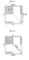
- FIG. 3 shows a first configuration of a memory buffer of an interleaver of FIG. 2
- FIG. 4 shows a second configuration of a memory buffer of the interleaver of FIG. 2.
- the transmitter I according to the second preferred embodiment of the present invention has the same configuration as that of the first preferred embodiment except an IDFT unit 210
- the receiver II according to the second preferred embodiment of the present invention has the same configuration as that of the first preferred embodiment except a DFT unit.
- the IDFT unit 210 comprises a mapper 110, serial to parallel converters 121 through 12m, a parallel to serial converter and guard interval inserter 140, and an interleaver 211 including MxN memory buffers provided between first and second IDFT units 212 and 213.
- the serial to parallel converters 121 through 12m sequentially receive the mapped MQAM symbols, and convert them into vector data.
- Respective m IDFT units of the first N-point IDFT unit 212 receive the vector data, perform IDFT on them, and transmit respective output values to the interleaver 211.
- the interleaver 211 writes subchannel values of the output signals received from m IDFT units in the memory buffers in the vertical (or temporal) direction, and when the interleaver 211 finishes writing the subchannel values for N pilot symbol blocks, the second N-point IDFT unit 213 reads the memory buffers in the vertical (or frequency) direction from the written memory buffers.
- FIG. 3 shows a write and read process into/from the memory buffer.
- FIG. 3 shows a first configuration of a memory buffer of the interleaver of FIG. 2.
- the interleaver 211 comprises MxN memory buffers, and numbers provided on the respective buffers represent subchannel values of the output signals received from the m IDFT units.
- the above-configured interleaver 211 writes the subchannel values of the buffers in the vertical (or temporal) direction so that the second N-point IDFT unit 213 may read channel values with less autocorrelations from among the written subchannels values.
- the respective subchannels with greater autocorrelations are stored temporarily, sequentially, and from top to bottom, and the subchannels with less autocorrelations from among them are read in the frequency direction, thereby improving the system performance.
- the second N-point IDFT unit 213 performs Fourier transform on the read subchannels, and transmits them to the parallel to serial converter and guard interval inserter 140 so that the information transmit vector added with a guard interval may be converted into a serial signal, and be then output.
- the total system performance is improved by reading subchannel values with less autocorrelations of a channel and demodulating them with respect to the OFDM signal.
- the performance of the wireless communication system according to the second preferred embodiment may be varied according to methods of what direction the interleaver 211 writes the respective subchannels or what direction the second N-point IDFT unit 213 reads them. That is, better performance is obtained by reducing the autocorrelations of the channel multiplied to the information transmit vector through the deinterleaving process of the receiver following the write and read direction.
- the second N-point IDFT unit 213 reads written channel values in the frequency direction in parallel with the row direction (the horizontal direction). This method obtains better performance compared to the write process in the diagonal direction.
- the distortion signal H i (k) caused by the frequency selective fading channel in Equation 4 has two-dimensional autocorrelations as given in Equation 10.
- ⁇ L is a delay time of the L-th path in the multipath channel
- ⁇ 2 / ⁇ l is a mean power of an L-th path signal
- the total mean power for each power is normalized to be 1. Therefore, the autocorrelations are influenced in the frequency direction by a delay profile of the fading channel.
- R (0,b) is given as Equation 11.
- u is a unit step function
- N G is a guard interval.
- the autocorrelations are influenced in the frequency direction by the maximum Doppler frequency, a number of subchannels, the guard interval, and the bandwidth l/ T s of the signal.
- the optimal operation method of the interleaver 211 for improvements of performance can be described through the above description of FIG. 3.
- the write operation is performed on the subchannel values in the diagonal direction as shown in FIG. 4 in the fading channel with a delay profile, and the subchannel values are interleaved in the horizontal direction so that the fading channel may be configured with subchannels with less autocorrelations, thereby achieving better performance.
- the interleaving is performed in the temporal direction to reduce the autocorrelations of the channel caused by the Doppler spreading, and accordingly, the OFDM method generates better performance in the frequency non-selective channel.
- the wireless communication system according to the second preferred embodiment not only improves the system performance following the new channel compensation method as described in the first preferred embodiment, but also obtains better performance through interleaving and deinterleaving for less autocorrelations of the channel.
- the number and the configuration of the IDFT units in the first N-point IDFT unit can be varied, which will now be described with reference to figures.
- FIG. 5 shows a detailed configuration of a wireless communication system according to a third preferred embodiment of the present invention
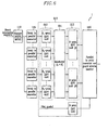
- FIG. 6 shows a detailed configuration of a wireless communication system according to a fourth preferred embodiment of the present invention.
- the wireless communication system according to the third preferred embodiment of the present invention has the same configuration as that of the first preferred embodiment except the IDFT unit 510, and has the same configuration as that of the second preferred embodiment except the number (a single number) of the second N-point IDFT units and the configuration of the first N 1 -point IDFT unit.
- the receiver II also has the same configuration as that of the first and second preferred embodiments, except the DFT unit.
- the wireless communication system reduces complexity of realization by reducing calculation including the IDFT and DFT processes, and hence, it requires complex calculation of (N /2)log 2 N so as to configure the N-point IDFT units as described in the second preferred embodiment.
- the wireless communication system according to the fourth preferred embodiment shown in FIG. 6 has the same configuration as that of the first preferred embodiment except an IDFT unit 610, and it has the same configuration as that of the second preferred embodiment except the number of second N-point IDFT units and the configuration of the first N 1 -point IDFT units in the IDFT unit 610.
- the receiver II has the same configuration as those of the first and second preferred embodiments except the DFT unit.
- the wireless communication system aims at reducing complexity of realization and calculation of the IDFT and the DFT, and it comprises LxM first N1-point IDFT units 612, L second N-point IDFT units 213, and an interleaver 611 including MxL memory buffers provided therebetween.
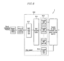
- FIG. 8 shows a detailed configuration of a wireless communication system (a transmitter) according to a fifth preferred embodiment of the present invention. As shown, the wireless communication system has the same configuration as that of the second embodiment except the IDFT unit 810.
- the wireless communication system uses an MxN-point IDFT unit 812 in the transmitter I, and a DFT unit in the receiver II to thereby improve the performance.
- the MxN memory buffer 811 shown in FIG. 8 does not perform the interleaving function.
- FIG. 9 shows a detailed configuration of a wireless communication system according to a sixth preferred embodiment of the present invention.
- the receiver II comprises an N-point IDFT unit 965 excluding the first and second N-point DFT units 161 and 165.
- the wireless communication system according to the sixth preferred embodiment requires no IDFT unit for information transmit symbol vector in the receiver II.
- the transmitter I of the wireless communication system comprises a mapper 910 for converting binary information transmit sequences into MQAM (or MPSK) symbols, a serial to parallel converter 920 for converting the MQAM symbols into vectors, a memory 930 for reading a modulated pilot symbol stored in the memory after IDFT is performed on the pilot symbol with a previously optimized PAR (peak-to-average ratio), and a parallel to serial converter and guard interval inserter 940 for converting the MQAM symbol vectors into parallel signals, inserting a guard interval found by a cyclic extension thereinto, and transmitting them.
- a mapper 910 for converting binary information transmit sequences into MQAM (or MPSK) symbols
- a serial to parallel converter 920 for converting the MQAM symbols into vectors
- a memory 930 for reading a modulated pilot symbol stored in the memory after IDFT is performed on the pilot symbol with a previously optimized PAR (peak-to-average ratio)
- a parallel to serial converter and guard interval inserter 940 for converting the M
- the receiver II comprises a guard interval eliminator and serial to parallel converter 950 for eliminating a guard interval from a receive signal and converting serial data into parallel data, a DFT unit 961 for converting information transmit symbol vectors to the frequency domain, a channel predictor and interpolating filter 963 for predicting a channel of the information transmit symbol vector by using a demodulated pilot symbol vector when the DFT unit 962 demodulates the pilot symbol vector, a channel compensator 964 for compensating the channel through an equalizer, an IDFT unit 965 for demodulating the channel-compensated information transmit symbol vector through the IDFT, a parallel to serial converter 970 for converting the demodulated signal into a serial signal, and a decoder 980 for restoring the converted signal into a binary information sequence.
- a guard interval eliminator and serial to parallel converter 950 for eliminating a guard interval from a receive signal and converting serial data into parallel data
- a DFT unit 961 for converting information transmit symbol vectors to the frequency domain
- the wireless communication system according to the sixth embodiment reduces hardwired complexity by eliminating the two IDFT units from the transmitter and the receiver differing from the first preferred embodiment.
- an A/D (analog to digital) converter and a D/A (digital to analog) converter require high dynamic ranges which increase the costs and cause a clipping phenomenon in which a large part of the amplitude is cut off because of the backoff effect of a power amplifier, and the clipping phenomenon generates signal distortion and lowers system performance.
- the wireless communication system according to the fifth preferred embodiment uses no IDFT unit, no performance lowering because of the PAR is generated, and effective performance improvements are obtained.
- the wireless communication system controls the noise enhancement caused by the channel compensation in an interval with a lesser amplitude of the channel into mean values within a symbol interval to reduce error rates and improve system performance.
- the wireless communication system performs interleaving and deinterleaving so as to lessen the autocorrelations of the channel at the time of compensating the channel, and restores them, thereby achieving better performance.
- the OFDM-based wireless communication system and the channel compensation method reduces error rates in the interval with a lesser channel amplitude to improve the total system performance, obtain data rates twice faster than the conventional data rates, and achieve twice the economy with the same frequency.
Landscapes
- Engineering & Computer Science (AREA)
- Power Engineering (AREA)
- Computer Networks & Wireless Communication (AREA)
- Signal Processing (AREA)
- Digital Transmission Methods That Use Modulated Carrier Waves (AREA)
- Mobile Radio Communication Systems (AREA)
- Cable Transmission Systems, Equalization Of Radio And Reduction Of Echo (AREA)
Applications Claiming Priority (4)
| Application Number | Priority Date | Filing Date | Title |
|---|---|---|---|
| KR2003019201 | 2003-03-27 | ||
| KR20030019201 | 2003-03-27 | ||
| KR1020030028227A KR100542114B1 (ko) | 2003-03-27 | 2003-05-02 | 직교 주파수 분할 다중화 기반의 무선 통신 시스템 및 그 채널 보상 방법 |
| KR2003028227 | 2003-05-02 |
Publications (3)
| Publication Number | Publication Date |
|---|---|
| EP1463251A2 true EP1463251A2 (fr) | 2004-09-29 |
| EP1463251A3 EP1463251A3 (fr) | 2007-02-21 |
| EP1463251B1 EP1463251B1 (fr) | 2009-02-25 |
Family
ID=32829129
Family Applications (1)
| Application Number | Title | Priority Date | Filing Date |
|---|---|---|---|
| EP03028180A Expired - Lifetime EP1463251B1 (fr) | 2003-03-27 | 2003-12-08 | Transmission multiporteuse à estimation de canal |
Country Status (3)
| Country | Link |
|---|---|
| US (2) | US7548522B2 (fr) |
| EP (1) | EP1463251B1 (fr) |
| CN (1) | CN100583707C (fr) |
Cited By (2)
| Publication number | Priority date | Publication date | Assignee | Title |
|---|---|---|---|---|
| WO2007075044A3 (fr) * | 2005-12-27 | 2009-05-14 | Lg Electronics Inc | Appareil pour la transmission de donnees utilisant des porteuse et procede associe |
| CN102045290A (zh) * | 2010-04-30 | 2011-05-04 | 西安电子科技大学 | 基于灰建模的ofdm窄带慢衰落慢时变信道估计方法 |
Families Citing this family (21)
| Publication number | Priority date | Publication date | Assignee | Title |
|---|---|---|---|---|
| WO2006105689A1 (fr) * | 2005-04-07 | 2006-10-12 | Zte Corporation | Methode et dispositif de reduction de la complexite du traitement des signaux des terminaux mobiles |
| US20060280113A1 (en) * | 2005-06-10 | 2006-12-14 | Huo David D | Method and apparatus for dynamic allocation of pilot symbols |
| KR101084139B1 (ko) * | 2005-06-15 | 2011-11-17 | 엘지전자 주식회사 | DFT spread OFDMA 시스템의 파일럿 전송방법 |
| JP2007074618A (ja) * | 2005-09-09 | 2007-03-22 | Sony Corp | 無線通信装置及び無線通信方法、並びにコンピュータ・プログラム |
| DE102006038825A1 (de) * | 2006-08-18 | 2008-02-21 | Nokia Siemens Networks Gmbh & Co.Kg | Funk-Kommunikationssystem, Netzeinrichtung und Verfahren zum Übertragen von Daten in einem Funk-Kommunikationssystem |
| US7558191B2 (en) * | 2006-09-07 | 2009-07-07 | Alcatel-Lucent Usa Inc. | Method of OFDM communication using superposition coding |
| JP5003147B2 (ja) * | 2006-12-26 | 2012-08-15 | ソニー株式会社 | 信号処理装置および信号処理方法、並びにプログラム |
| CN101335733B (zh) * | 2007-06-29 | 2013-02-20 | 安捷伦科技有限公司 | 正交频分复用系统中的载波间干扰测量 |
| US20090059782A1 (en) * | 2007-08-29 | 2009-03-05 | Rgb Systems, Inc. | Method and apparatus for extending the transmission capability of twisted pair communication systems |
| JP5052280B2 (ja) * | 2007-10-01 | 2012-10-17 | 株式会社日立国際電気 | 受信機 |
| WO2010079868A1 (fr) | 2009-01-09 | 2010-07-15 | Lg Electronics Inc. | Appareil pour la transmission et la réception d'un signal et procédé de transmission et de réception d'un signal |
| WO2010101328A1 (fr) | 2009-03-03 | 2010-09-10 | Lg Electronics Inc. | Appareil d'émission et de réception d'un signal et procédé d'émission et de réception d'un signal |
| EP2539798B1 (fr) | 2010-02-26 | 2021-04-14 | Synaptics Incorporated | Démodulation variable permettant d'éviter les interférences |
| US9898121B2 (en) | 2010-04-30 | 2018-02-20 | Synaptics Incorporated | Integrated capacitive sensing and displaying |
| KR102105355B1 (ko) * | 2012-08-22 | 2020-04-28 | 삼성전자주식회사 | 대역 확산 기반 시스템을 위한 트레이닝 시퀀스와 채널 추정방법 |
| US9600121B2 (en) * | 2014-04-25 | 2017-03-21 | Synaptics Incorporated | Driving sensor electrodes for noise measurement |
| CN105187339B (zh) * | 2014-06-06 | 2018-12-07 | 华为技术有限公司 | 一种双选信道的补偿方法、系统及相关装置 |
| US20160273957A1 (en) * | 2015-03-19 | 2016-09-22 | National Instruments Corporation | Machine Condition Monitoring Using Phase Adjusted Frequency Referenced Vector Averaging |
| TR201716332A2 (tr) | 2017-10-23 | 2019-05-21 | T C Istanbul Medipol Ueniversitesi | Kanal temelli̇ dönüşüm kullanan güvenli̇ ve uyum sağlayan di̇kgen bölmeli̇ dalga şeki̇lleri̇ çoğullama si̇stemi̇ |
| CN112260980B (zh) * | 2020-10-27 | 2021-10-26 | 南京大学 | 一种基于超前预测实现相位噪声补偿的硬件系统及其实现方法 |
| CN116132242B (zh) * | 2023-02-07 | 2024-08-09 | 北京理工大学 | 一种基于幅值均衡的通感融合性能优化方法 |
Family Cites Families (18)
| Publication number | Priority date | Publication date | Assignee | Title |
|---|---|---|---|---|
| SE9302453L (sv) * | 1993-07-20 | 1994-10-17 | Telia Ab | Förfarande och anordning för synkronisering i digitalt transmissionssystem av typen OFDM |
| JPH0746217A (ja) * | 1993-07-26 | 1995-02-14 | Sony Corp | ディジタル復調装置 |
| JP3556047B2 (ja) * | 1996-05-22 | 2004-08-18 | 三菱電機株式会社 | ディジタル放送受信機 |
| WO1998009385A2 (fr) | 1996-08-29 | 1998-03-05 | Cisco Technology, Inc. | Traitement spatio-temporel pour telecommunications |
| US7027464B1 (en) * | 1999-07-30 | 2006-04-11 | Matsushita Electric Industrial Co., Ltd. | OFDM signal transmission scheme, and OFDM signal transmitter/receiver |
| US6985432B1 (en) * | 2000-01-28 | 2006-01-10 | Zion Hadad | OFDM communication channel |
| KR100317384B1 (ko) | 1999-12-27 | 2001-12-24 | 구자홍 | 채널 특성 보정 방법 |
| US6928120B1 (en) * | 2000-09-25 | 2005-08-09 | Cingular Wireless Ii, Llc | Methods and apparatus for use in reducing residual phase error in OFDM communication signals |
| JP3462468B2 (ja) * | 2000-11-27 | 2003-11-05 | 松下電器産業株式会社 | Ofdm受信装置、ofdm送信装置およびofdm通信方法 |
| KR100434473B1 (ko) | 2001-05-11 | 2004-06-05 | 삼성전자주식회사 | 직교주파수 분할 다중 시스템에서 채널 복호 장치 및 방법 |
| JP3782330B2 (ja) * | 2001-09-14 | 2006-06-07 | 富士通株式会社 | Ofdm受信方法及びofdm受信装置 |
| US20040047284A1 (en) * | 2002-03-13 | 2004-03-11 | Eidson Donald Brian | Transmit diversity framing structure for multipath channels |
| KR100464014B1 (ko) * | 2002-03-21 | 2004-12-30 | 엘지전자 주식회사 | 다중 입출력 이동 통신 시스템에서의 폐루프 신호 처리 방법 |
| WO2004021616A1 (fr) * | 2002-08-28 | 2004-03-11 | Fujitsu Limited | Appareil de transmission/reception et procede de transmission/reception |
| KR100553544B1 (ko) * | 2002-08-31 | 2006-02-20 | 삼성탈레스 주식회사 | 버스트 직교 주파수분할 다중 전송 시스템에서 주파수 오프셋 추정 및 채널 등화방법 |
| KR100757264B1 (ko) * | 2005-12-29 | 2007-09-11 | 전자부품연구원 | 연결선 지연 고장 테스트 제어기 및 이를 이용한 연결선고장 테스트 장치 |
| EP2169866A4 (fr) * | 2007-07-09 | 2014-07-09 | Sharp Kk | Procédé de planification et dispositif de station de commande |
| CN101803255B (zh) * | 2007-09-12 | 2013-11-20 | 夏普株式会社 | 无线通信方法、无线通信系统和无线发送装置 |
-
2003
- 2003-11-24 US US10/720,701 patent/US7548522B2/en not_active Expired - Fee Related
- 2003-11-28 CN CN200310115744A patent/CN100583707C/zh not_active Expired - Fee Related
- 2003-12-08 EP EP03028180A patent/EP1463251B1/fr not_active Expired - Lifetime
-
2009
- 2009-04-15 US US12/424,405 patent/US8155073B2/en not_active Expired - Fee Related
Cited By (4)
| Publication number | Priority date | Publication date | Assignee | Title |
|---|---|---|---|---|
| WO2007075044A3 (fr) * | 2005-12-27 | 2009-05-14 | Lg Electronics Inc | Appareil pour la transmission de donnees utilisant des porteuse et procede associe |
| US8401095B2 (en) | 2005-12-27 | 2013-03-19 | Lg Electronics Inc. | Apparatus for transmitting data using carriers and method thereof |
| CN102045290A (zh) * | 2010-04-30 | 2011-05-04 | 西安电子科技大学 | 基于灰建模的ofdm窄带慢衰落慢时变信道估计方法 |
| CN102045290B (zh) * | 2010-04-30 | 2013-03-20 | 西安电子科技大学 | 基于灰建模的ofdm窄带慢衰落慢时变信道估计方法 |
Also Published As
| Publication number | Publication date |
|---|---|
| EP1463251A3 (fr) | 2007-02-21 |
| CN1534910A (zh) | 2004-10-06 |
| CN100583707C (zh) | 2010-01-20 |
| US20050073948A1 (en) | 2005-04-07 |
| US8155073B2 (en) | 2012-04-10 |
| EP1463251B1 (fr) | 2009-02-25 |
| US20090219803A1 (en) | 2009-09-03 |
| US7548522B2 (en) | 2009-06-16 |
Similar Documents
| Publication | Publication Date | Title |
|---|---|---|
| US8155073B2 (en) | Orthogonal frequency division multiplexing wireless communication operable on frequency selective channel, and channel compensation method | |
| Narasimhamurthy et al. | OFDM systems for wireless communications | |
| US7496028B2 (en) | Apparatus and method for minimizing PAPR in an OFDM communication system | |
| US7394865B2 (en) | Signal constellations for multi-carrier systems | |
| US7961800B2 (en) | Adaptive radio/modulation apparatus, receiver apparatus, wireless communication system, and wireless communication method | |
| Rohling et al. | Broad-band OFDM radio transmission for multimedia applications | |
| JP4746809B2 (ja) | Ofdmにおける2つの伝搬チャネルの推定 | |
| CN1961513B (zh) | 多载波通信环境中语音业务的自适应调度 | |
| US7420957B2 (en) | Mobile termile capable of efficiently measuring CNIR and CNIR measuring method thereof | |
| US7817735B2 (en) | Device and method of performing channel estimation for OFDM-based wireless communication system | |
| US20120039379A1 (en) | Receiver apparatus for receiving a multicarrier signal | |
| US20030142754A1 (en) | Apparatus and method for reducing PAPR in an OFDM mobile communication system | |
| US20060274641A1 (en) | Method and apparatus for constant envelope orthogonal frequency division multiplexing in a wireless system | |
| US20100061474A1 (en) | Fft spreading among selected ofdm sub-carriers | |
| US20060115010A1 (en) | Apparatus and method for reducing a peak to average power ratio in a multi-carrier communication system | |
| Kadel | Diversity and equalization in frequency domain a robust and flexible receiver technology for broadband mobile communication systems | |
| US7346041B2 (en) | Processing of an OFDM signal | |
| KR100542114B1 (ko) | 직교 주파수 분할 다중화 기반의 무선 통신 시스템 및 그 채널 보상 방법 | |
| US20070127361A1 (en) | Ofdm transmission apparatus, ofdm reception apparatus, and method | |
| Wang et al. | 64-QAM OFDM with TCM coding and waveform shaping in a time-selective Rician fading channel | |
| Alasswi et al. | Performance Analysis of MIMO-OFDM Systems under Different Modulation Schemes and Channel Conditions Using Various Transform Techniques | |
| Van der Perre et al. | A single-carrier/OFDM comparison for broadband wireless communication | |
| Prabhu et al. | A PAPR reduction technique in OFDM transmissions using hierarchical QAM | |
| Mendes et al. | On The Performance of WH-STC-OFDM and WH-SFC-OFDM in Non-Linear Time Variant Channels | |
| Zhou et al. | Performance of 2D FFT modulated signal over multipath fading channels |
Legal Events
| Date | Code | Title | Description |
|---|---|---|---|
| PUAI | Public reference made under article 153(3) epc to a published international application that has entered the european phase |
Free format text: ORIGINAL CODE: 0009012 |
|
| 17P | Request for examination filed |
Effective date: 20040105 |
|
| AK | Designated contracting states |
Kind code of ref document: A2 Designated state(s): AT BE BG CH CY CZ DE DK EE ES FI FR GB GR HU IE IT LI LU MC NL PT RO SE SI SK TR |
|
| AX | Request for extension of the european patent |
Extension state: AL LT LV MK |
|
| PUAL | Search report despatched |
Free format text: ORIGINAL CODE: 0009013 |
|
| AK | Designated contracting states |
Kind code of ref document: A3 Designated state(s): AT BE BG CH CY CZ DE DK EE ES FI FR GB GR HU IE IT LI LU MC NL PT RO SE SI SK TR |
|
| AX | Request for extension of the european patent |
Extension state: AL LT LV MK |
|
| 17Q | First examination report despatched |
Effective date: 20070829 |
|
| AKX | Designation fees paid |
Designated state(s): AT BE BG CH CY CZ DE DK EE ES FI FR GB GR HU IE IT LI LU MC NL PT RO SE SI SK TR |
|
| GRAP | Despatch of communication of intention to grant a patent |
Free format text: ORIGINAL CODE: EPIDOSNIGR1 |
|
| GRAS | Grant fee paid |
Free format text: ORIGINAL CODE: EPIDOSNIGR3 |
|
| RAP1 | Party data changed (applicant data changed or rights of an application transferred) |
Owner name: JWA, JEONG-WOO Owner name: KTFREETEL CO., LTD |
|
| GRAA | (expected) grant |
Free format text: ORIGINAL CODE: 0009210 |
|
| AK | Designated contracting states |
Kind code of ref document: B1 Designated state(s): AT BE BG CH CY CZ DE DK EE ES FI FR GB GR HU IE IT LI LU MC NL PT RO SE SI SK TR |
|
| REG | Reference to a national code |
Ref country code: GB Ref legal event code: FG4D |
|
| REG | Reference to a national code |
Ref country code: CH Ref legal event code: EP |
|
| REG | Reference to a national code |
Ref country code: IE Ref legal event code: FG4D |
|
| REF | Corresponds to: |
Ref document number: 60326319 Country of ref document: DE Date of ref document: 20090409 Kind code of ref document: P |
|
| REG | Reference to a national code |
Ref country code: SE Ref legal event code: TRGR |
|
| PG25 | Lapsed in a contracting state [announced via postgrant information from national office to epo] |
Ref country code: SI Free format text: LAPSE BECAUSE OF FAILURE TO SUBMIT A TRANSLATION OF THE DESCRIPTION OR TO PAY THE FEE WITHIN THE PRESCRIBED TIME-LIMIT Effective date: 20090225 |
|
| PG25 | Lapsed in a contracting state [announced via postgrant information from national office to epo] |
Ref country code: AT Free format text: LAPSE BECAUSE OF FAILURE TO SUBMIT A TRANSLATION OF THE DESCRIPTION OR TO PAY THE FEE WITHIN THE PRESCRIBED TIME-LIMIT Effective date: 20090225 |
|
| PG25 | Lapsed in a contracting state [announced via postgrant information from national office to epo] |
Ref country code: BE Free format text: LAPSE BECAUSE OF FAILURE TO SUBMIT A TRANSLATION OF THE DESCRIPTION OR TO PAY THE FEE WITHIN THE PRESCRIBED TIME-LIMIT Effective date: 20090225 |
|
| PG25 | Lapsed in a contracting state [announced via postgrant information from national office to epo] |
Ref country code: DK Free format text: LAPSE BECAUSE OF FAILURE TO SUBMIT A TRANSLATION OF THE DESCRIPTION OR TO PAY THE FEE WITHIN THE PRESCRIBED TIME-LIMIT Effective date: 20090225 Ref country code: ES Free format text: LAPSE BECAUSE OF FAILURE TO SUBMIT A TRANSLATION OF THE DESCRIPTION OR TO PAY THE FEE WITHIN THE PRESCRIBED TIME-LIMIT Effective date: 20090605 Ref country code: EE Free format text: LAPSE BECAUSE OF FAILURE TO SUBMIT A TRANSLATION OF THE DESCRIPTION OR TO PAY THE FEE WITHIN THE PRESCRIBED TIME-LIMIT Effective date: 20090225 Ref country code: CZ Free format text: LAPSE BECAUSE OF FAILURE TO SUBMIT A TRANSLATION OF THE DESCRIPTION OR TO PAY THE FEE WITHIN THE PRESCRIBED TIME-LIMIT Effective date: 20090225 Ref country code: PT Free format text: LAPSE BECAUSE OF FAILURE TO SUBMIT A TRANSLATION OF THE DESCRIPTION OR TO PAY THE FEE WITHIN THE PRESCRIBED TIME-LIMIT Effective date: 20090812 |
|
| PG25 | Lapsed in a contracting state [announced via postgrant information from national office to epo] |
Ref country code: SK Free format text: LAPSE BECAUSE OF FAILURE TO SUBMIT A TRANSLATION OF THE DESCRIPTION OR TO PAY THE FEE WITHIN THE PRESCRIBED TIME-LIMIT Effective date: 20090225 Ref country code: RO Free format text: LAPSE BECAUSE OF FAILURE TO SUBMIT A TRANSLATION OF THE DESCRIPTION OR TO PAY THE FEE WITHIN THE PRESCRIBED TIME-LIMIT Effective date: 20090225 |
|
| PLBE | No opposition filed within time limit |
Free format text: ORIGINAL CODE: 0009261 |
|
| STAA | Information on the status of an ep patent application or granted ep patent |
Free format text: STATUS: NO OPPOSITION FILED WITHIN TIME LIMIT |
|
| PG25 | Lapsed in a contracting state [announced via postgrant information from national office to epo] |
Ref country code: BG Free format text: LAPSE BECAUSE OF FAILURE TO SUBMIT A TRANSLATION OF THE DESCRIPTION OR TO PAY THE FEE WITHIN THE PRESCRIBED TIME-LIMIT Effective date: 20090525 |
|
| 26N | No opposition filed |
Effective date: 20091126 |
|
| PG25 | Lapsed in a contracting state [announced via postgrant information from national office to epo] |
Ref country code: MC Free format text: LAPSE BECAUSE OF NON-PAYMENT OF DUE FEES Effective date: 20100701 |
|
| REG | Reference to a national code |
Ref country code: CH Ref legal event code: PL |
|
| PG25 | Lapsed in a contracting state [announced via postgrant information from national office to epo] |
Ref country code: CH Free format text: LAPSE BECAUSE OF NON-PAYMENT OF DUE FEES Effective date: 20091231 Ref country code: LI Free format text: LAPSE BECAUSE OF NON-PAYMENT OF DUE FEES Effective date: 20091231 Ref country code: IE Free format text: LAPSE BECAUSE OF NON-PAYMENT OF DUE FEES Effective date: 20091208 Ref country code: GR Free format text: LAPSE BECAUSE OF FAILURE TO SUBMIT A TRANSLATION OF THE DESCRIPTION OR TO PAY THE FEE WITHIN THE PRESCRIBED TIME-LIMIT Effective date: 20090526 |
|
| PG25 | Lapsed in a contracting state [announced via postgrant information from national office to epo] |
Ref country code: IT Free format text: LAPSE BECAUSE OF FAILURE TO SUBMIT A TRANSLATION OF THE DESCRIPTION OR TO PAY THE FEE WITHIN THE PRESCRIBED TIME-LIMIT Effective date: 20090225 |
|
| PG25 | Lapsed in a contracting state [announced via postgrant information from national office to epo] |
Ref country code: LU Free format text: LAPSE BECAUSE OF NON-PAYMENT OF DUE FEES Effective date: 20091208 |
|
| PG25 | Lapsed in a contracting state [announced via postgrant information from national office to epo] |
Ref country code: HU Free format text: LAPSE BECAUSE OF FAILURE TO SUBMIT A TRANSLATION OF THE DESCRIPTION OR TO PAY THE FEE WITHIN THE PRESCRIBED TIME-LIMIT Effective date: 20090826 |
|
| PG25 | Lapsed in a contracting state [announced via postgrant information from national office to epo] |
Ref country code: TR Free format text: LAPSE BECAUSE OF FAILURE TO SUBMIT A TRANSLATION OF THE DESCRIPTION OR TO PAY THE FEE WITHIN THE PRESCRIBED TIME-LIMIT Effective date: 20090225 |
|
| PG25 | Lapsed in a contracting state [announced via postgrant information from national office to epo] |
Ref country code: CY Free format text: LAPSE BECAUSE OF FAILURE TO SUBMIT A TRANSLATION OF THE DESCRIPTION OR TO PAY THE FEE WITHIN THE PRESCRIBED TIME-LIMIT Effective date: 20090225 |
|
| PGFP | Annual fee paid to national office [announced via postgrant information from national office to epo] |
Ref country code: GB Payment date: 20141219 Year of fee payment: 12 Ref country code: FI Payment date: 20141211 Year of fee payment: 12 Ref country code: DE Payment date: 20141211 Year of fee payment: 12 Ref country code: SE Payment date: 20141219 Year of fee payment: 12 |
|
| PGFP | Annual fee paid to national office [announced via postgrant information from national office to epo] |
Ref country code: FR Payment date: 20141219 Year of fee payment: 12 Ref country code: NL Payment date: 20141219 Year of fee payment: 12 |
|
| REG | Reference to a national code |
Ref country code: DE Ref legal event code: R119 Ref document number: 60326319 Country of ref document: DE |
|
| REG | Reference to a national code |
Ref country code: SE Ref legal event code: EUG |
|
| GBPC | Gb: european patent ceased through non-payment of renewal fee |
Effective date: 20151208 |
|
| PG25 | Lapsed in a contracting state [announced via postgrant information from national office to epo] |
Ref country code: SE Free format text: LAPSE BECAUSE OF NON-PAYMENT OF DUE FEES Effective date: 20151209 |
|
| REG | Reference to a national code |
Ref country code: NL Ref legal event code: MM Effective date: 20160101 |
|
| REG | Reference to a national code |
Ref country code: FR Ref legal event code: ST Effective date: 20160831 |
|
| PG25 | Lapsed in a contracting state [announced via postgrant information from national office to epo] |
Ref country code: DE Free format text: LAPSE BECAUSE OF NON-PAYMENT OF DUE FEES Effective date: 20160701 Ref country code: GB Free format text: LAPSE BECAUSE OF NON-PAYMENT OF DUE FEES Effective date: 20151208 Ref country code: NL Free format text: LAPSE BECAUSE OF NON-PAYMENT OF DUE FEES Effective date: 20160101 |
|
| PG25 | Lapsed in a contracting state [announced via postgrant information from national office to epo] |
Ref country code: FR Free format text: LAPSE BECAUSE OF NON-PAYMENT OF DUE FEES Effective date: 20151231 |
|
| PG25 | Lapsed in a contracting state [announced via postgrant information from national office to epo] |
Ref country code: FI Free format text: LAPSE BECAUSE OF NON-PAYMENT OF DUE FEES Effective date: 20151208 |