EP1464314A1 - Whirlpoolwanne - Google Patents
Whirlpoolwanne Download PDFInfo
- Publication number
- EP1464314A1 EP1464314A1 EP03405161A EP03405161A EP1464314A1 EP 1464314 A1 EP1464314 A1 EP 1464314A1 EP 03405161 A EP03405161 A EP 03405161A EP 03405161 A EP03405161 A EP 03405161A EP 1464314 A1 EP1464314 A1 EP 1464314A1
- Authority
- EP
- European Patent Office
- Prior art keywords
- jets
- modular
- moulded shell
- spa bath
- bores
- Prior art date
- Legal status (The legal status is an assumption and is not a legal conclusion. Google has not performed a legal analysis and makes no representation as to the accuracy of the status listed.)
- Withdrawn
Links
- XLYOFNOQVPJJNP-UHFFFAOYSA-N water Substances O XLYOFNOQVPJJNP-UHFFFAOYSA-N 0.000 claims abstract description 32
- 238000000034 method Methods 0.000 claims abstract description 6
- 238000004519 manufacturing process Methods 0.000 claims abstract description 5
- 238000003856 thermoforming Methods 0.000 claims abstract description 4
- 238000005553 drilling Methods 0.000 claims description 3
- 239000004814 polyurethane Substances 0.000 claims description 2
- 210000002414 leg Anatomy 0.000 description 7
- 239000000463 material Substances 0.000 description 7
- 238000007789 sealing Methods 0.000 description 4
- 210000000689 upper leg Anatomy 0.000 description 4
- 210000005252 bulbus oculi Anatomy 0.000 description 2
- 235000009508 confectionery Nutrition 0.000 description 2
- 230000000694 effects Effects 0.000 description 2
- 238000000465 moulding Methods 0.000 description 2
- 239000004033 plastic Substances 0.000 description 2
- 229920003023 plastic Polymers 0.000 description 2
- 239000004793 Polystyrene Substances 0.000 description 1
- 241000270934 Rana catesbeiana Species 0.000 description 1
- 239000000853 adhesive Substances 0.000 description 1
- 230000001070 adhesive effect Effects 0.000 description 1
- 238000010276 construction Methods 0.000 description 1
- 230000003028 elevating effect Effects 0.000 description 1
- 210000003128 head Anatomy 0.000 description 1
- 238000007373 indentation Methods 0.000 description 1
- 238000012986 modification Methods 0.000 description 1
- 230000004048 modification Effects 0.000 description 1
- 230000002093 peripheral effect Effects 0.000 description 1
- 230000000704 physical effect Effects 0.000 description 1
- 229920002223 polystyrene Polymers 0.000 description 1
- 230000007704 transition Effects 0.000 description 1
Images


Classifications
-
- A—HUMAN NECESSITIES
- A61—MEDICAL OR VETERINARY SCIENCE; HYGIENE
- A61H—PHYSICAL THERAPY APPARATUS, e.g. DEVICES FOR LOCATING OR STIMULATING REFLEX POINTS IN THE BODY; ARTIFICIAL RESPIRATION; MASSAGE; BATHING DEVICES FOR SPECIAL THERAPEUTIC OR HYGIENIC PURPOSES OR SPECIFIC PARTS OF THE BODY
- A61H33/00—Bathing devices for special therapeutic or hygienic purposes
- A61H33/60—Components specifically designed for the therapeutic baths of groups A61H33/00
- A61H33/601—Inlet to the bath
- A61H33/6021—Nozzles
- A61H33/6063—Specifically adapted for fitting in bathtub walls
-
- A—HUMAN NECESSITIES
- A61—MEDICAL OR VETERINARY SCIENCE; HYGIENE
- A61H—PHYSICAL THERAPY APPARATUS, e.g. DEVICES FOR LOCATING OR STIMULATING REFLEX POINTS IN THE BODY; ARTIFICIAL RESPIRATION; MASSAGE; BATHING DEVICES FOR SPECIAL THERAPEUTIC OR HYGIENIC PURPOSES OR SPECIFIC PARTS OF THE BODY
- A61H33/00—Bathing devices for special therapeutic or hygienic purposes
- A61H33/0087—Therapeutic baths with agitated or circulated water
Definitions
- the invention relates to spa baths comprising a moulded shell with modular inserts arranged in recesses of the moulded shell, whereby jets operate through bores in the modular inserts.
- the invention further relates to a process for manufacture of a spa bath.
- US patent 6,256,805 shows a modular system for spas.
- the jets are mounted on jet panels that cover recesses in the moulded shell constituting the tub of the spa.
- the moulded shell is penetrated only at a single point and the water distribution for the jets is arranged within the moulded shell, comprising a channel extending inside the shell, along the peripheral edge of the tub. This arrangement alleviates the replacement of malfunctioning jets or the upgrade to a new jet configuration.
- the flexibility and safety of the system is improved.
- the solution of the invention is specified by the features of claim 1.
- the water distribution is arranged substantially outside the moulded shell, i. e. outside the cavity defined by the shell.
- the same preferably applies to the air distribution, which is normally needed as well for jets used in spa baths.
- the modular inserts are of a simple construction which reduces their cost. Besides, confection of the spa baths is made easier. Nevertheless, the flexibility of the system is preserved as choosing the arrangement of jets happens only after the moulding of the shell.
- each jet is supplied by water directly through a bore in the moulded shell, whereby the bore in the moulded shell is arranged immediately rearward of the bore in the modular insert.
- This arrangement minimizes the demand for space concerning the distribution of water for the jets.
- the jet delivers the water into the tub through the bore in the modular insert and is directly supplied with water through the bore in the moulded shell. Therefore, there is no need for any further distribution of water inside the moulded shell.
- Each bore in the moulded shell is sealed up against the inside of the shell.
- a plurality of close-by jets are combined in one element that fits a respective bore in the modular insert and that is supplied by water through a single bore in the moulded shell, rearward of the element.
- the jets are directly affixed to the moulded shell.
- the attachment of the jet preferably comprises as well the sealing against water flowing out of the inside of the moulded shell. This way, the jets are firmly mounted and the modular inserts do not have to be mounted such that they are sealed against the recess of the shell.
- the jets may be fixed to the modular insert, thus requiring a sealing of the insert against the shell.
- the jets may be attached to both the modular insert as well as the moulded shell. Thereby, by tightly fixing the jets the insert is automatically fixed to the shell, without the need for additional fixation.
- the jets are arranged such that their mouths are arranged below the surface of the modular inserts in order to protect a user of the spa bath. It may be inconvenient if the mouth of a jet directly contacts the skin of a user. For certain types of jets such an arrangement even inhibits their proper operation. Therefore, arranging the mouths of the jets below the surface of the modular insert and therefore below the actual surface of the tub protects the users against harm due to jets elevating above the surface of the tub and at the same time improves the operation of the jets.
- certain types of jets may be mounted such that their mouths lie in the surface plane of the tub, e. g. jets that are disposed outside the contact surfaces with the user's body.
- the mounting depth of each jet may be adapted to the type of jet as well as to the portion of the body the jet acts on.
- the modular inserts are substantially made of polyurethane (PU), this being a durable, inexpensive and easy to work material which provides for comfortable rests, due to its surface structure and its other physical properties.
- PU polyurethane
- the modular inserts have a thickness corresponding to the depth of the recesses, preferably 30-40 mm.
- the inserts having the same thickness as the depth of the recesses lead to a smooth surface of the tub, constituted by the moulded shell and - at recessed portions - the inserts.
- a thickness of 30-40 mm allows for mounting the jets such that their mouths are arranged below the surface of the inserts and at the same time for keeping the width of the skirt and thereby the extent of the spa bath reasonably small. This thickness further permits to produce cushion-like soft inserts that are very comfortable rests for users of the spa bath.
- the thickness of the inserts may be larger than the depth of the recesses, namely if the inserts have the form of a seat, supporting the whole body of a user.
- the thickness of the inserts may be as well smaller than the depth of the recesses, particularly if the edge of the recess is designed to support the body in a seat-like form.
- the absolute thickness of the insert (and of the recess) may be reduced to even less than 30 mm, thereby allowing for an even narrower skirt of the spa bath.
- the modular inserts are hollow, i.e. the modular insert is constituted by a shell defining a cavity. This reduces material requirements and therefore the weight of the inserts. At the same time, their comfort for the user is improved.
- the inserts may be compactly formed of a light material or made of a shell of a durable strong material filled by another light material, e. g. polystyrene.
- the insert may be formed of a ductile cover filled with a soft gel.
- the recesses and modular inserts are arranged in portions of the spa bath supporting backs and/or legs of users of the spa bath. These are the portions where jets are primarily needed, e. g. to effect a massage of the back or of the legs.
- Further recesses and inserts may e. g. be arranged in portions of the spa bath where feet of the users are positioned, to effect a foot massage.
- a process for manufacture of a spa bath comprises the following steps:
- the bores are drilled immediately rearward of bores in the modular insert through which jets will be operating. This simplifies the mounting of the jets and avoids the need for any water distribution inside the moulded shell.
- the figures 1A, 1B, 1 C show different modular inserts 1a, 1b, 1c for supporting the back of a user of the spa bath, having different arrangements of bores 2, 3 for mounting jets. All the different inserts 1 a, 1 b, 1 c fit into the same recess 5 of a moulded shell 4.
- Figure 1 A displays a modular insert 1a adapted to the form of the user's upper part of the body.
- the insert 1a features five small circular bores 2a for mounting small jets arranged along the upper edge of the insert and three larger circular bores 3a arranged along the symmetry axis of the insert 1 a.
- the smaller bores 2a provide a massage of the neck of the user and the larger bores 3a provide a massage along the spine of the user.
- the moulded shell 4 shows a recess 5 extending from a ground region of the tub into the upper border of the moulded shell 4.
- the form of the recess 5 is exactly adapted to the form of the modular insert 1a such that if the insert 1a is positioned in the recess 5 the tub shows a smooth surface.
- bores 6a corresponding to the locations and adapted to the diameter of the smaller bores 2a in the insert 1a and bores 7a corresponding to the locations and adapted to the diameter of the larger bores 3a in the insert 1 a are drilled into the recess 1a of the moulded shell 4.
- the bores 2a, 3a in the insert 1a and the corresponding bores 6a, 7a in the recess are concentric and therefore continuous straight bores from outside the moulded shell 4 until the inside of the tub are created.
- the diameter of the bores 6a, 7a in the recess 5 of the moulded shell 4 is smaller than the diameter of the bores 2a, 3a in the modular insert 1 a. This allows for the mounting of jets into the bores 6a, 7a of the moulded shell 4 whose outer portion, situated in front of the moulded shell, i. e. inside the moulded shell, features a larger diameter than the bores 6a or 7a respectively. Thereby, the bore is sealed and the jet is supported on the moulded shell 4.
- the diameter of the bores 2a, 3a in the modular insert is large enough to receive the front part of the jet including its outer portion.
- Figure 1 B displays a variant of a modular insert, featuring another arrangement of small bores 2b and larger bores 3b in the modular insert 1b. Only two small bores 2b are arranged along the upper edge of the insert but six larger bores 3b are arranged in the back region of the insert 1b. Accordingly, the bores 6b. 7b drilled into the recess 4 of the moulded shell 5 show the same, different configuration. Apart from that, the situation is alike the one shown in Figure 1A.
- Figure 1c displays a third variant of a modular insert, featuring in addition one large oval bore 3d arranged on the symmetry axis and near the bottom end of the insert 1c.
- the small circular bores 2c are disposed in two rows near the upper end of the insert 1c, the larger circular bores 3c in a horizontal row disposed between the small bores 2c and the large oval bore 3d.
- bores 6c, 7c, 8c are drilled at the respective positions in the recess 5 of the moulded shell 4.
- Bore 8c corresponding to the oval bore 3d in the modular insert 1c shows an oval form. It may receive a specially designed oval jet or two usual circular jets arranged on a common oval element.
- Figure 2 shows modular inserts supporting the back and the legs of the user as well as their arrangement in recesses of the spa bath according to the invention.
- Figure 2A is a ground view, depicting a modular insert 9 supporting the back of the user and a modular insert 10 supporting portions of the legs, namely the thighs, of the user.
- the modular insert 9 comprises a single circular bore 11, arranged on the symmetry axis of the insert and adapted to receive a respective jet 16.
- the modular insert 10 comprises four circular bores 12 having the same size arranged on a rectangle to receive four respective jets 17. Both elements fit into corresponding recesses 5, 13 in the moulded shell 4.
- Figure 2B is a cross-sectional view of the modular insert 9 along its symmetry axis, depicting as well the respective portion of the moulded shell 4, the water supply 14 and the air supply 15 for the jets 16,17.
- the modular insert 9 supporting the back of the user extends from almost the ground of the tub up into the upper border of the moulded shell 4.
- the uppermost portion 9a fitting into a portion of the recess situated in the border is 90° offset to the main portion of the modular insert 9. This provides for a smooth transition between the tub itself and its border.
- the shape of the modular insert 9 is adapted to the human body.
- the modular insert 10 supporting the users thighs has a straight form fitting into a respective recess 13.
- the water supply 14 comprises three water pipes 14a, 14b, 14c, whereby pipe 14a supplies the single jet 16 arranged in the modular insert 9 supporting the back of the user.
- Pipes 14b, 14c each supply two jets 17 arranged in the modular insert 10 supporting the thighs of the user. All the pipes are arranged below of and parallel to the surface of the moulded insert 4. They show a small distance to the moulded insert 4 such that the connection to the jets 16, 17 is short. Parallel and adjacent to all the water pipes 14a, 14b, 14c air pipes 15a, 15b, 15c are disposed.
- Figure 3 is a ground view of the position of the modular inserts 9, 10 in respect of the user.
- the single modular insert 9 is supporting the user's back extending up to support the user's head.
- Two modular inserts 10 are provided. The first one corresponds to the one displayed in Figure 2, supporting the users thighs. The second one is built up identically but arranged such that it supports the user's lower legs.
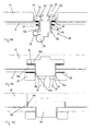
- Figures 4A-4C are cross-sectional views of variants of a jet attached to a recess of the inventive spa bath, along the symmetry axis of the jet.
- FIG 4A displays a first variant where the jet is attached to the moulded shell, and where the modular insert can be freely removed or inserted without being affected by the jet.
- the jet 18 is disposed in a recess region of the moulded shell 4. It is attached by a wall fitting 21 of a substantially cylindrical form, having a flange 21 a at its upper end and a thread 21 b along the outside of its shaft.
- the wall fitting 21 reaches through a bore 19 in the moulded shell 4 and is sealed against the surface of the moulded shell by gasket 20 arranged between the flange 21 a and the inner surface of the moulded shell 4.
- the jet 18 is fixed by means of a thread 18b arranged on the inside of a shaft 18a of the jet tightened against the thread 21 of the wall fitting.
- a gasket 22 provides sealing of the jet 18 against the outside of the moulded shell 4.
- the mouth of the jet is constituted by an eyeball 23 mounted between the wall fitting 21 and an escutcheon 24, sealed by an O-Ring 25.
- the eyeball 23 is universally rotatable such that the direction of the mouth of the jet may be varied.
- the escutcheon 24 is fixed to the wall fitting 21 by means of a clip (not visible in the cross-section displayed).
- the mouth of the jet allows for delivering the water through a bore 26 of a modular insert 27. There is a distance of the mouth to the surface 28 of the tub such that the user feels comfortable and such that the operation of the jet 18 is improved.
- a water pipe 29 is connected to jet 18 as well as an air pipe 30.
- FIG. 4B displays an alternative attachment of a jet 32, where the details of the jet 32 are not displayed.
- any type of jet may be employed.
- a modular insert 31 comprising a protrusion 31 a with which an upper part 32a of the jet 32 co-operates is employed, such that the modular insert 31 is automatically held affixed as soon as the jet 32 is fastened.
- a gasket 33 is arranged between the upper part 32a of the jet 32 and the protrusion 31a of the modular insert 31.
- the jet 32 is fixed by means of a nut 34 having a thread 34a that co-operates with a thread 32c arranged along the shaft 32b of the jet 32.
- An additional gasket 35 is arranged in between the nut 34 and the outside of the moulded shell 4. Water and air are supplied by usual supply means 36 and 37 respectively.
- FIG. 4C displays another alternative, where a jet 38 is attached to a modular insert 39 by means of corresponding threads 38a, 39a.
- the invention may be realised without substantial modifications using all the different kinds of jets such as e.g. jets fed by water and air, by water and pulsed air, by water alone (if need be furnished with a pump) etc.
- jets e.g. jets fed by water and air, by water and pulsed air, by water alone (if need be furnished with a pump) etc.
- the usual jets available for spa baths may be used with the invention.
- the modular inserts are not attached by fixation of the jets, as e. g. displayed in Fig. 4A, they are attached to the moulded shell by any of the known means, such as screws, adhesive sealing, latches etc.
- the size, form and arrangement of recesses in the moulded shell may be varied depending on the flexibility desired. Embodiments featuring only a few large recesses, that e. g. correspond to modular inserts constituting complete seats, are possible as well as other embodiments comprising a larger number of rather small recesses. Above all in the latter case it may be preferable to employ as well modular inserts that do not show bores, for certain places where no jets are desired in a given arrangement of the spa bath.
- the invention creates a spa bath comprising a moulded shell with modular inserts arranged in recesses of the moulded shell, whereby jets operate through bores in the modular inserts, that may be manufactured inexpensively and allows for a skirt surrounding the tub having a small width.
Landscapes
- Health & Medical Sciences (AREA)
- Public Health (AREA)
- Epidemiology (AREA)
- Pain & Pain Management (AREA)
- Physical Education & Sports Medicine (AREA)
- Rehabilitation Therapy (AREA)
- Life Sciences & Earth Sciences (AREA)
- Animal Behavior & Ethology (AREA)
- General Health & Medical Sciences (AREA)
- Veterinary Medicine (AREA)
- Percussion Or Vibration Massage (AREA)
Priority Applications (1)
| Application Number | Priority Date | Filing Date | Title |
|---|---|---|---|
| EP03405161A EP1464314A1 (de) | 2003-03-07 | 2003-03-07 | Whirlpoolwanne |
Applications Claiming Priority (1)
| Application Number | Priority Date | Filing Date | Title |
|---|---|---|---|
| EP03405161A EP1464314A1 (de) | 2003-03-07 | 2003-03-07 | Whirlpoolwanne |
Publications (1)
| Publication Number | Publication Date |
|---|---|
| EP1464314A1 true EP1464314A1 (de) | 2004-10-06 |
Family
ID=32842892
Family Applications (1)
| Application Number | Title | Priority Date | Filing Date |
|---|---|---|---|
| EP03405161A Withdrawn EP1464314A1 (de) | 2003-03-07 | 2003-03-07 | Whirlpoolwanne |
Country Status (1)
| Country | Link |
|---|---|
| EP (1) | EP1464314A1 (de) |
Citations (7)
| Publication number | Priority date | Publication date | Assignee | Title |
|---|---|---|---|---|
| DE2613529A1 (de) * | 1974-04-11 | 1976-10-21 | Angelo Rocco D | Einrichtung fuer unterwassermassage |
| WO1988000037A1 (en) * | 1986-07-08 | 1988-01-14 | New Technologies, Inc. | Hydrotherapy bathtub |
| US5333324A (en) * | 1992-11-06 | 1994-08-02 | John Pinciaro | Hydrotherapy hot tub structure for neck and shoulder massage |
| US5682625A (en) * | 1995-10-13 | 1997-11-04 | Dimension One Spas, Inc. | Hot tub with adjustable headrest with water jet |
| US5754989A (en) * | 1996-07-10 | 1998-05-26 | Ludlow; David Jon | Plumbing and shell system for spa |
| US5928171A (en) * | 1994-10-12 | 1999-07-27 | Watkins Manufacturing Corporation | Neck jet pillow for tub spas |
| US6186964B1 (en) * | 1996-09-27 | 2001-02-13 | Tony J. Branham | Hydro-massage pillow system |
-
2003
- 2003-03-07 EP EP03405161A patent/EP1464314A1/de not_active Withdrawn
Patent Citations (7)
| Publication number | Priority date | Publication date | Assignee | Title |
|---|---|---|---|---|
| DE2613529A1 (de) * | 1974-04-11 | 1976-10-21 | Angelo Rocco D | Einrichtung fuer unterwassermassage |
| WO1988000037A1 (en) * | 1986-07-08 | 1988-01-14 | New Technologies, Inc. | Hydrotherapy bathtub |
| US5333324A (en) * | 1992-11-06 | 1994-08-02 | John Pinciaro | Hydrotherapy hot tub structure for neck and shoulder massage |
| US5928171A (en) * | 1994-10-12 | 1999-07-27 | Watkins Manufacturing Corporation | Neck jet pillow for tub spas |
| US5682625A (en) * | 1995-10-13 | 1997-11-04 | Dimension One Spas, Inc. | Hot tub with adjustable headrest with water jet |
| US5754989A (en) * | 1996-07-10 | 1998-05-26 | Ludlow; David Jon | Plumbing and shell system for spa |
| US6186964B1 (en) * | 1996-09-27 | 2001-02-13 | Tony J. Branham | Hydro-massage pillow system |
Similar Documents
| Publication | Publication Date | Title |
|---|---|---|
| US8671471B2 (en) | Bath | |
| EP2914232B1 (de) | Whirlpool- und badesysteme mit verbesserten auswechselbaren düsenmodulen | |
| US6467103B1 (en) | Sound transmission system and illumination system for a tub, spa, pool, bath or shower | |
| US10993875B2 (en) | Tub with swirl ports and dispenser | |
| US20100187326A1 (en) | Waterfall Unit | |
| US20050172395A1 (en) | Configurable modular shower surround features | |
| ITRM20110143U1 (it) | Vasca per idromassaggio. | |
| EP1726283A1 (de) | Tragbares Spa | |
| EP1464314A1 (de) | Whirlpoolwanne | |
| US10426298B2 (en) | Capped rim system for a bathtub | |
| EP1713429B1 (de) | Luftbad | |
| US11951071B2 (en) | Heated massage pillow | |
| US20090083903A1 (en) | Spa | |
| JP6538536B2 (ja) | 吐水装置とこれを備える浴槽装置 | |
| JP2019055235A (ja) | 吐水装置及び浴槽装置 | |
| US20220133588A1 (en) | Hot tub with varied water levels | |
| JP6480075B1 (ja) | 吐水装置及び浴槽装置 | |
| US7434277B1 (en) | Fluid flow system | |
| KR20200001339U (ko) | 높이조절이 가능한 베개 | |
| CN223026364U (zh) | 一种下肢按摩熏蒸装置 | |
| JP2003052564A (ja) | 温水シャワー内蔵の浴用いす | |
| US20260115097A1 (en) | Interchangeable jet modules for a spa and/or bathing system | |
| EP2446874A1 (de) | Massagespa | |
| KR200422028Y1 (ko) | 안마기 장착용 수족온욕기 | |
| KR20050024983A (ko) | 허리운동기능을 갖는 회전의자 |
Legal Events
| Date | Code | Title | Description |
|---|---|---|---|
| PUAI | Public reference made under article 153(3) epc to a published international application that has entered the european phase |
Free format text: ORIGINAL CODE: 0009012 |
|
| AK | Designated contracting states |
Kind code of ref document: A1 Designated state(s): AT BE BG CH CY CZ DE DK EE ES FI FR GB GR HU IE IT LI LU MC NL PT RO SE SI SK TR |
|
| AX | Request for extension of the european patent |
Extension state: AL LT LV MK |
|
| 111Z | Information provided on other rights and legal means of execution |
Free format text: ATBEBGCHCYCZDEDKEEESFIFRGBGRHUIEITLILUMCNLPTROSESISKTR Effective date: 20041123 |
|
| AKX | Designation fees paid | ||
| RAP1 | Party data changed (applicant data changed or rights of an application transferred) |
Owner name: SPIRAL SPAS SA Owner name: G.S.B. GLOBAL SANITARY BUSINESS LIMITED |
|
| REG | Reference to a national code |
Ref country code: DE Ref legal event code: 8566 |
|
| STAA | Information on the status of an ep patent application or granted ep patent |
Free format text: STATUS: THE APPLICATION IS DEEMED TO BE WITHDRAWN |
|
| 18D | Application deemed to be withdrawn |
Effective date: 20050407 |