EP1464367A2 - Snowboard binding - Google Patents
Snowboard binding Download PDFInfo
- Publication number
- EP1464367A2 EP1464367A2 EP04003348A EP04003348A EP1464367A2 EP 1464367 A2 EP1464367 A2 EP 1464367A2 EP 04003348 A EP04003348 A EP 04003348A EP 04003348 A EP04003348 A EP 04003348A EP 1464367 A2 EP1464367 A2 EP 1464367A2
- Authority
- EP
- European Patent Office
- Prior art keywords
- snowboard binding
- instep
- binding according
- guide
- snowboard
- Prior art date
- Legal status (The legal status is an assumption and is not a legal conclusion. Google has not performed a legal analysis and makes no representation as to the accuracy of the status listed.)
- Granted
Links
Images


Classifications
-
- A—HUMAN NECESSITIES
- A63—SPORTS; GAMES; AMUSEMENTS
- A63C—SKATES; SKIS; ROLLER SKATES; DESIGN OR LAYOUT OF COURTS, RINKS OR THE LIKE
- A63C9/00—Ski bindings
- A63C9/002—Strap closures or latches; Leashes
-
- A—HUMAN NECESSITIES
- A63—SPORTS; GAMES; AMUSEMENTS
- A63C—SKATES; SKIS; ROLLER SKATES; DESIGN OR LAYOUT OF COURTS, RINKS OR THE LIKE
- A63C10/00—Snowboard bindings
- A63C10/02—Snowboard bindings characterised by details of the shoe holders
- A63C10/04—Shoe holders for passing over the shoe
-
- A—HUMAN NECESSITIES
- A63—SPORTS; GAMES; AMUSEMENTS
- A63C—SKATES; SKIS; ROLLER SKATES; DESIGN OR LAYOUT OF COURTS, RINKS OR THE LIKE
- A63C10/00—Snowboard bindings
- A63C10/02—Snowboard bindings characterised by details of the shoe holders
- A63C10/04—Shoe holders for passing over the shoe
- A63C10/06—Straps therefor, e.g. adjustable straps
-
- A—HUMAN NECESSITIES
- A63—SPORTS; GAMES; AMUSEMENTS
- A63C—SKATES; SKIS; ROLLER SKATES; DESIGN OR LAYOUT OF COURTS, RINKS OR THE LIKE
- A63C10/00—Snowboard bindings
- A63C10/24—Calf or heel supports, e.g. adjustable high back or heel loops
Definitions
- the invention relates to a snowboard binding according to the Preamble of claim 1.
- This binding has one on the surface of the snowboard Basic element to be fastened, a fastened to it Partially spanning top of a snowboard boot Instep element and a pivotally articulated to the base element supporting the back of the snowboard boot Heel element.
- the instep element is large in that it the snowboard boot in its toe area and its Instep area covered.
- the instep element is adjustable in length Straps, namely a toe strap and one Instep strap attached to the base element. In the closed position the binding is the boot between the Basic element, the instep element and the heel element held.
- the adjustment of the binding to different sized boots takes place on the one hand via a length adjustment of the Strap holding instep element as well as adjustable Position of the pivotable heel element, which by a fastened in the front area of the base element, the Height-adjustable heel element at the back Strap is made.
- a similar snowboard binding is also from the US 5,556,123 A1 known, where the fixation of the heel element is designed differently.
- Softbinding is also commonly referred to as "Softbinding” because it is relative soft, flexible boots (so-called soft boots) are used, which gives the driver a relatively large flexibility of movement bid both forward and to the side.
- Softbinding Through the mentioned setting of instep and heel element can Flexibility, i.e. the possible range of motion be so that the driver can choose a large or small freedom of movement of the boot in the binding Has.
- the boot shaft has the problem that the instep element, which is relatively tight on the outer top the boot lies in the area of the toes and instep, this lateral bending movement is limited, in particular if the instep element, as in the above-mentioned state of Technology, is large-scale and largely the forefoot and instep area of the boot covered and adapted to its contour. Even if the instep element is made of flexible material, with this configuration, the lateral movement of the boot severely hampered, which is a disadvantage is because with this type of binding the high Flexibility of moving forward and to the side is desirable.
- the object of the invention is therefore the snowboard binding of the type mentioned to improve in that increased flexibility for movements of the boot in the bond is created and especially for a lateral buckling or rolling of the boot in the Binding.
- the basic principle of the invention is that the instep element slidable along at least one arcuate path and thus the lateral bending or rolling movement of the boot.
- the arcuate path is secured by at least one belt, preferably by two straps, namely a toe strap and an instep strap formed the instep element outside reach over and hold. On this strap and the instep element interacting guide means are provided which the limit arcuate path.
- the management means exist in the case of a concrete design from slot-like guide openings in the belt and a guide pin on the instep element, the guide pin reaches through the guide openings of the belt and is guided on the side walls.
- the belts remain essentially unchanged while the Instep element is displaceable relative to the belt and thus in the broader sense a swiveling movement around an Area of the sole of the foot or swivel axis still below can execute.
- damping means are present at the ends of the guide openings, which dampen movement close to the respective limit position.
- damping means are preferably narrowing of the Guideway, the width of which is smaller than the diameter of the pin or inserts made of elastic material. to the pins have safe guidance at their free ends a thickened head spanning the guide openings so that there is always a secure connection between the Instep element and the belt is given.
- the relative displaceability between instep element and Belts can also be locked.
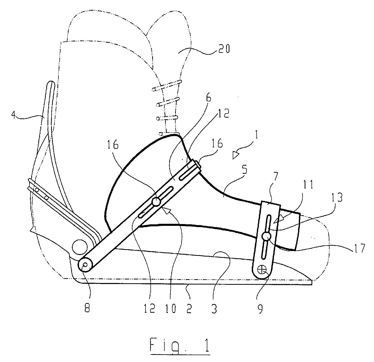
- Fig. 1 shows a schematic side view of the snowboard binding 1, the one on the surface of a not shown Has basic element 2 to be fastened to snowboards, which is essentially one on each of its long sides has vertically upward side wall 3, the Is part of the basic element. On both side walls is in the back of the binding no closer to descriptive heel element 4 pivotally arranged can be pivoted backwards to open the binding can and to close the binding forward, taking it in a known manner (cf. DE 44 35 113 C1) in the closed position is fixable.
- the binding also has an instep element 5, which is shown here is large and the instep and toe area of a boot 20 covered and because of it inner flexibility is adaptable to its contour.
- the Instep element 5 is held on two arcuate straps, namely an instep strap 6 and a toe strap 7, the Ends at the base element 2 and more precisely at its base Side walls 3 are attached to pivot bearings 8 and 9.
- the two straps 6 and 7 are made of flexible, bendable material, but they have one in the longitudinal direction high tensile strength. Belts 6 and 7 overlap this Instep element 5 on the outside thereof.
- the instep element 5 is relative to that of the straps 6 and 7 formed arcuate path slidably. To this The purpose of the instep element is via guide means 10 and 11 attached to straps 6 and 7.
- These leadership tools consist of the embodiment shown here slot-like guide openings 12 and 13 in the belt 6 and 7 and from one attached to the instep element 5
- Guide pin 16, 17 through the said guide openings 12 or 13 passes through and at its free end has a thickened head 16 'which is larger than the width of the guide openings 11 and 12 and thus this overlaps.
- the pin 16, 17 is thus along the guide openings 11 or 12 displaceable, so that it is fixed with the pins 16, 17 coupled instep element can follow this movement, which is formed by the arcuate path.
- Timing belts 21 and 22 are in this fastening device 23 or 24 introduced and there by positive connection fixed.
- the instep element 5 is in a neutral Center position shown.
- the guide pins 16 and 17 lie in the middle of the guide openings 12 or 13th
- the instep element 5 is in a swivel position shown.
- Pins 16 and 17 are each on one End of the guide openings 12 and 13 come to a stop. It should be noted that the respective limit positions can also be asymmetrical, i.e. that the swivel motion of the instep element in one direction is larger than that other.
- the shift in Pins 16 and 17 on the front strap 7 and on the rear strap 6 can be of different sizes since the instep element 5 is flexible in itself and thus deformations of the boot 20 can follow and since the lateral shift in The instep area can be larger than in the toe area.
- Fig. 4 shows a plan view of a section of the Guide means 10 with the guide opening 12 and in these inserted guide pin 16.
- damping means consist of a tapered constriction 15 of the guide opening 12, the width of the narrowing being continuous towards the end decreases and is smaller than the diameter of the pin 16. If the pin 16 slides into this constriction 15, so the constriction 15 must be widened, which is under Tension standing belt 6 a mechanical deformation work causes the energy consumed and the movement of the Pin 16 presents a resistance along the constriction 15, which increases towards the end of the constriction 15. At the same time, the frictional forces between the pin 16 and the wall of the constriction 15, which is the movement attenuates.
- an insert 25 is provided which extends into the guide opening 12 in the area where the end is inserted.
- the insert 25 exists made of rubber-elastic material. As soon as the pin 16 against the insert 25 stops, the insert deforms 25 increasing and thus forms an increasing resistance against further displacement of the pin 16 so that the damping effect is also achieved.
- the two described Damping means of the constriction 15 and the insert 25 can also be combined with one another, i.e. simultaneously in the area of one or both ends of the guide opening 12 can be attached. It is also possible to use one or both damping means only on one side of the guide opening to install.
- the insert 25 can also be designed to be exchangeable be, so that the driver can choose an application with different Can use damping characteristics.
- the relative displacement between the instep element 5 and the respective belt 6 and / or 7 can also be locked or be deactivated.
- a transverse to its longitudinal direction Gearing 26 provided and a corresponding one Counter teeth 27 on the underside of the thickened head 16 'of the pin 16.
- the pin and head are then attached so that it can be turned at least 90 °.
- the teeth 26 and 27 aligned at right angles to each other, so that the corresponding teeth cannot interlock, but rather their tips slide onto each other, so that the movability is guaranteed.
- This can the driver also by an arrow 28 on the top of the head are signaled.
- the pin 16 will be velvet Head 16 'rotated by 90 °, the teeth are parallel to each other so that the teeth can interlock and thus the movability is blocked. So that is it is also possible to have a predetermined relative position between Select and fix instep element 5 and straps 6 or 7.
- the pin 16 attached to instep element 5 by fastening means 18 is.
- fastening means 18 can be riveted or screwed on his.
- the pin 16 one has widened head 16 'of the guide opening 12 of the belt 6 engages and thus an involuntary Loosening of the instep element 5 prevented from the belt 6.
- the toothing 26, 27 described can be clearly seen, here also the pin 16 together with the head 16 'so aligned is that sliding is possible.
- management means 10 and 11 can also be configured differently, for example can have a dovetail guide, a guide with Double U profile or other known in mechanical engineering Guides are used.
- 1 to 3 are three guides per belt 6 and 7 10 and 11 attached laterally on both sides and in the middle.
- the guide only on both sides of the instep element 5 to attach or only in the middle of the instep element 5 or only on one side or only on one side and the Center.
- Other combinations are also conceivable in which for example, only one guide on the front toe strap 7 is attached, while on the rear instep strap 6 two or three tours are available.
- the instep element 5 even from a single strap can be held.
- two straps 6 and 7 are used, the instep element 5 divided into two elements, each of which then one of the straps 6 or 7 is attached. It can also be sufficient if only that on the rear instep strap fastened element according to the invention is displaceable, while the front element remains immovable because the movement in the instep area is more important than in the toe area.
Landscapes
- Footwear And Its Accessory, Manufacturing Method And Apparatuses (AREA)
- Materials Applied To Surfaces To Minimize Adherence Of Mist Or Water (AREA)
- Suspension Of Electric Lines Or Cables (AREA)
- Bridges Or Land Bridges (AREA)
Abstract
Die Snowboardbindung hat ein Grundelement (2), das an der
Oberseite eines Snowboards befestigbar ist. An dem Grundelement
ist mindestens ein einen Snowboardstiefel (20)
teilweise übergreifendes Ristelement (5) befestigt. Zur
Verbesserung der Beweglichkeit des Stiefels in der Bindung
ist das Ristelement (5) längs mindestens einer bogenförmigen
Bahn (10, 11) verschieblich (Fig. 1).
Description
Die Erfindung betrifft eine Snowboardbindung gemäß dem
Oberbegriff des Patentanspruches 1.The invention relates to a snowboard binding according to the
Preamble of
Eine solche Bindung ist aus der DE 44 35 113 C1 (= US 5,918,897; EP 0 705 625 B1, JP 8-206275 A1) bekannt. Diese Bindung hat ein auf der Oberfläche des Snowboards zu befestigendes Grundelement, ein daran befestigtes, die Oberseite eines Snowboardstiefels teilweise übergreifendes Ristelement und ein an dem Grundelement schwenkbar angelenktes, die Rückseite des Snowboardstiefels abstützendes Fersenelement. Das Ristelement ist dabei großflächig, daß es den Snowboardstiefel in dessen Zehenbereich und dessen Ristbereich überdeckt. Das Ristelement ist über längenverstellbare Riemen, nämlich einen Zehenriemen und einen Ristriemen an dem Grundelement befestigt. In der Schließstellung der Bindung ist der Stiefel somit zwischen dem Grundelement, dem Ristelement und dem Fersenelement gehalten. Die Anpassung der Bindung an unterschiedlich große Stiefel erfolgt einerseits über eine Längeneinstellung der das Ristelement haltenden Riemen als auch über die einstellbare Lage des schwenkbaren Fersenelementes, welches durch einen im vorderen Bereich des Grundelementes befestigten, das Fersenelement hinten umgreifenden, längenverstellbaren Gurt erfolgt.Such a bond is from DE 44 35 113 C1 (= US 5,918,897; EP 0 705 625 B1, JP 8-206275 A1). This binding has one on the surface of the snowboard Basic element to be fastened, a fastened to it Partially spanning top of a snowboard boot Instep element and a pivotally articulated to the base element supporting the back of the snowboard boot Heel element. The instep element is large in that it the snowboard boot in its toe area and its Instep area covered. The instep element is adjustable in length Straps, namely a toe strap and one Instep strap attached to the base element. In the closed position the binding is the boot between the Basic element, the instep element and the heel element held. The adjustment of the binding to different sized boots takes place on the one hand via a length adjustment of the Strap holding instep element as well as adjustable Position of the pivotable heel element, which by a fastened in the front area of the base element, the Height-adjustable heel element at the back Strap is made.
Eine ähnliche Snowboardbindung ist auch aus der US 5,556,123 A1 bekannt, wobei dort die Fixierung des Fersenelementes unterschiedlich gestaltet ist.A similar snowboard binding is also from the US 5,556,123 A1 known, where the fixation of the heel element is designed differently.
Die oben genannten Bindungen werden allgemein auch als "Softbindung" bezeichnet, weil sie zusammen mit relativ weichen, flexiblen Stiefeln (sog. Softboots) benutzt werden, die dem Fahrer eine relativ große Flexibilität der Bewegung sowohl nach vorne als auch zur Seite bieten. Durch die genannte Einstellung von Rist- und Fersenelement kann die Flexibilität, d.h. der mögliche Bewegungsbereich, eingestellt werden, so daß der Fahrer je nach Wunsch einen großen oder kleinen Bewegungsspielraum des Stiefels in der Bindung hat.The above bonds are also commonly referred to as "Softbinding" is called because it is relative soft, flexible boots (so-called soft boots) are used, which gives the driver a relatively large flexibility of movement bid both forward and to the side. Through the mentioned setting of instep and heel element can Flexibility, i.e. the possible range of motion be so that the driver can choose a large or small freedom of movement of the boot in the binding Has.
Bei einem seitlichen Abwinkeln des Schienbeines und damit des Schaftes des Stiefels tritt aber das Problem auf, daß das Ristelement, welches relativ fest an der äußeren Oberseite des Stiefels im Bereich von Zehen und Rist aufliegt, diese seitliche Abknickbewegung begrenzt, insbesondere wenn das Ristelement, wie beim oben genannten Stand der Technik, großflächig ausgebildet ist und weitestgehend den Vorderfußbereich und den Ristbereich des Stiefels überdeckt und an dessen Kontur angepaßt ist. Selbst wenn das Ristelement aus flexiblem Material hergestellt ist, wird bei dieser Konfiguration doch die seitliche Bewegung des Stiefels stark behindert, was als Nachteil anzusehen ist, da gerade bei diesem Typ von Bindung die hohe Flexibilität der Bewegung nach vorne und zur Seite wünschenswert ist.If the shin is bent to the side and thus The boot shaft has the problem that the instep element, which is relatively tight on the outer top the boot lies in the area of the toes and instep, this lateral bending movement is limited, in particular if the instep element, as in the above-mentioned state of Technology, is large-scale and largely the forefoot and instep area of the boot covered and adapted to its contour. Even if the instep element is made of flexible material, with this configuration, the lateral movement of the boot severely hampered, which is a disadvantage is because with this type of binding the high Flexibility of moving forward and to the side is desirable.
Aufgabe der Erfindung ist es daher, die Snowboardbindung der eingangs genannten Art dahingehend zu verbessern, daß eine erhöhte Flexibilität für Bewegungen des Stiefels in der Bindung geschaffen wird und insbesondere für ein seitliches Abknicken oder Abrollen des Stiefels in der Bindung.The object of the invention is therefore the snowboard binding of the type mentioned to improve in that increased flexibility for movements of the boot in the bond is created and especially for a lateral buckling or rolling of the boot in the Binding.
Diese Aufgabe wird durch die im Patentanspruch 1 angegebenen
Merkmale gelöst. Vorteilhafte Ausgestaltungen und weiterbildungen
der Erfindung sind den Unteransprüchen zu entnehmen.This object is achieved by the specified in
Das Grundprinzip der Erfindung besteht darin, daß das Ristelement längs mindestens einer bogenförmigen Bahn verschieblich ist und damit die seitliche Abknick- oder Abrollbewegung des Stiefels mitmacht.The basic principle of the invention is that the instep element slidable along at least one arcuate path and thus the lateral bending or rolling movement of the boot.
Die bogenförmige Bahn wird durch mindestens einen Riemen, vorzugsweise durch zwei Riemen, nämlich einen Zehenriemen und einen Ristriemen gebildet, die das Ristelement außen übergreifen und halten. An diesem Riemen und dem Ristelement sind zusammenwirkende Führungsmittel vorgesehen, die die bogenförmige Bahn begrenzen.The arcuate path is secured by at least one belt, preferably by two straps, namely a toe strap and an instep strap formed the instep element outside reach over and hold. On this strap and the instep element interacting guide means are provided which the limit arcuate path.
Bei einer konkreten Ausgestaltung bestehen die Führungsmittel aus langlochartigen Führungsöffnungen in den Riemen und einem Führungsstift an dem Ristelement, wobei der Führungsstift durch die Führungsöffnungen des Riemens hindurchgreift und an dessen Seitenwänden geführt ist.The management means exist in the case of a concrete design from slot-like guide openings in the belt and a guide pin on the instep element, the guide pin reaches through the guide openings of the belt and is guided on the side walls.
Bei einer seitlichen Abrollbewegung bleiben somit die Riemen im wesentlichen in unveränderter Position, während das Ristelement relativ zu den Riemen verschieblich ist und damit im weiteren Sinne eine Schwenkbewegung um eine im Bereich der Fußsohle oder noch darunter liegende Schwenkachse ausführen kann.In the event of a lateral rolling movement, the belts remain essentially unchanged while the Instep element is displaceable relative to the belt and thus in the broader sense a swiveling movement around an Area of the sole of the foot or swivel axis still below can execute.
Nach einer vorteilhaften Weiterbildung der Erfindung sind an den Enden der Führungsöffnungen Dämpfungsmittel vorhanden, die eine Bewegung nahe der jeweiligen Grenzstellung dämpfen. Diese Dämpfungsmittel sind vorzugsweise Verengungen der Führungsbahn, deren Weite kleiner ist als der Durchmesser des Stiftes oder Einsätze aus elastischem Material. Zur sicheren Führung weisen die Stifte an ihren freien Enden einen die Führungsöffnungen übergreifenden verdickten Kopf auf, so daß stets eine sichere Verbindung zwischen dem Ristelement und dem Riemen gegeben ist.According to an advantageous development of the invention damping means are present at the ends of the guide openings, which dampen movement close to the respective limit position. These damping means are preferably narrowing of the Guideway, the width of which is smaller than the diameter of the pin or inserts made of elastic material. to the pins have safe guidance at their free ends a thickened head spanning the guide openings so that there is always a secure connection between the Instep element and the belt is given.
Nach einer vorteilhaften Weiterbildung der Erfindung kann die relative Verschieblichkeit zwischen Ristelement und Riemen auch gesperrt werden. Zu diesem Zweck ist eine Verzahnung zwischen dem Kopf des jeweiligen Stiftes und der diesem gegenüberliegenden Außenseite des Riemens vorgesehen. Durch Drehen des Stiftes um 90° können die Verzahnungen parallel zueinander ausgerichtet sein und damit greifen oder senkrecht zueinander stehen, so daß die Spitzen der Zähne aufeinander abgleiten können.According to an advantageous development of the invention the relative displaceability between instep element and Belts can also be locked. For this purpose is a Tooth between the head of the respective pin and the opposite side of the belt intended. By turning the pin 90 ° you can Toothings are aligned parallel to each other and grab with it or stand perpendicular to each other so that the tips of the teeth can slide on each other.
Im folgenden wird die Erfindung anhand eines Ausführungsbeispieles im Zusammenhang mit der Zeichnung ausführlicher erläutert. Es zeigt:
- Fig. 1
- eine schematische Seitenansicht der Snowboardbindung nach der Erfindung;
- Fig. 2
- eine schematische Vorderansicht der Snowboardbindung in einer neutralen Stellung;
- Fig. 3
- eine schematische Vorderansicht der Snowboardbindung in einer Schwenkstellung;
- Fig. 4
- eine Draufsicht auf die Führungsmittel; und
- Fig. 5
- eine Schnittansicht gemäß der Schnittlinie x-x der Fig. 4.
- Fig. 1
- is a schematic side view of the snowboard binding according to the invention;
- Fig. 2
- a schematic front view of the snowboard binding in a neutral position;
- Fig. 3
- a schematic front view of the snowboard binding in a swivel position;
- Fig. 4
- a plan view of the guide means; and
- Fig. 5
- 3 shows a sectional view along the section line xx of FIG. 4.
Gleiche Bezugszeichen in den einzelnen Figuren bezeichnen gleiche bzw. funktionell einander entsprechende Teile.Identify the same reference numerals in the individual figures same or functionally corresponding parts.
Fig. 1 zeigt eine schematische Seitenansicht der Snowboardbindung
1, die ein auf der Oberfläche eines nicht dargestellten
Snowboards zu befestigendes Grundelement 2 aufweist,
welches an seinen Längsseiten jeweils eine im wesentlichen
senkrecht nach oben gerichtete Seitenwand 3 aufweist, die
Bestandteil des Grundelementes ist. An beiden Seitenwänden
ist im hinteren Bereich der Bindung ein nicht näher zu
beschreibendes Fersenelement 4 schwenkbar angeordnet, das
für ein Öffnen der Bindung nach hinten geschwenkt werden
kann und zum Schließen der Bindung nach vorne, wobei es
in bekannter Weise (vgl. DE 44 35 113 C1) in der Schließstellung
fixierbar ist.Fig. 1 shows a schematic side view of the snowboard binding
1, the one on the surface of a not shown
Has
Weiter weist die Bindung ein Ristelement 5 auf, das hier
großflächig ausgebildet ist und den Rist- und den Zehenbereich
eines Stiefels 20 überdeckt und aufgrund seiner
inneren Flexibilität an dessen Kontur anpaßbar ist. Das
Ristelement 5 ist an zwei bogenförmigen Riemen gehalten,
nämlich einem Ristriemen 6 und einem Zehenriemen 7, deren
Enden jeweils an dem Grundelement 2 und genauer an dessen
Seitenwänden 3 befestigt sind und zwar an Schwenklagern
8 bzw. 9. Die beiden Riemen 6 und 7 sind aus flexiblem,
biegbarem Material, sie haben in Längsrichtung jedoch eine
hohe Zugfestigkeit. Die Riemen 6 und 7 übergreifen das
Ristelement 5 an dessen Außenseite.The binding also has an
Das Ristelement 5 ist relativ zu der von den Riemen 6 und
7 gebildeten bogenförmigen Bahn verschiebbar. Zu diesem
Zweck ist das Ristelement über Führungsmittel 10 und 11
an den Riemen 6 und 7 befestigt. Diese Führungsmittel
bestehen bei dem hier gezeigten Ausführungsbeispiel aus
langlochartigen Führungsöffnungen 12 bzw. 13 in den Riemen
6 und 7 und aus einem an dem Ristelement 5 befestigten
Führungsstift 16, 17, der durch die genannten Führungsöffnungen
12 bzw. 13 hindurchgreift und an seinem freien Ende
einen verdickten Kopf 16' aufweist, die größer ist als
die Weite der Führungsöffnungen 11 bzw. 12 und diese somit
übergreift.The
Der Stift 16, 17 ist somit längs der Führungsöffnungen
11 bzw. 12 verschieblich, so daß das fest mit den Stiften
16, 17 gekoppelte Ristelement dieser Bewegung folgen kann,
die durch die bogenförmige Bahn gebildet ist.The
Zur Längenverstellung der beiden Riemen 6 und 7 sind an
sich bekannte Zahnriemen 21 und 22 in Kombination mit
Befestigungseinrichtungen 23 und 24 vorgesehen, die an
den Riemen 6 bzw. 7 angebracht sind. Die Zahnriemen 21
bzw. 22 werden in diese Befestigungsvorrichtung 23 bzw.
24 eingeführt und dort durch formschlüssige Verbindung
fixiert.To adjust the length of the two
In Fig. 2 ist das Ristelement 5 in einer neutralen
Mittelstellung dargestellt. Die Führungsstifte 16 und 17
liegen jeweils in der Mitte der Führungsöffnungen 12 bzw.
13.2, the
In Fig. 3 ist das Ristelement 5 in einer Schwenkstellung
dargestellt. Die Stifte 16 und 17 sind jeweils an einem
Ende der Führungsöffnungen 12 bzw. 13 zum Anschlag gekommen.
Es sei darauf hingewiesen, daß die jeweiligen Grenzstellungen
auch asymmetrisch sein können, d.h. daß die Schwenkbewegung
des Ristelementes in die eine Richtung größer ist als die
andere.3, the
Weiter sei darauf hingewiesen, daß die Verschiebung der
Stifte 16 und 17 am vorderen Riemen 7 und am hinteren Riemen
6 unterschiedlich groß sein kann, da das Ristelement 5
in sich flexibel ist und somit Verformungen des Stiefels
20 folgen kann und da die seitliche Verschiebung im
Ristbereich größer sein kann als im Zehenbereich.It should also be noted that the shift in
Fig. 4 zeigt eine Draufsicht auf einen Ausschnitt der
Führungsmittel 10 mit der Führungsöffnung 12 und dem in
diese eingesetzten Führungsstift 16. Um die Schwenkbewegung
zu dämpfen und einen harten Anschlag der Grenzstellungen
zu vermeiden, sind Dämpfungsmittel vorgesehen. Im linken
Teil der Fig. 4 bestehen diese Dämpfungsmittel aus einer
spitz zulaufenden Verengung 15 der Führungsöffnung 12,
wobei die Weite der Verengung zum Ende hin kontinuierlich
abnimmt und kleiner ist als der Durchmesser des Stiftes
16. Gleitet der Stift 16 in diese Verengung 15 hinein,
so muß die Verengung 15 aufgeweitet werden, was bei unter
Zugspannung stehenden Riemen 6 eine mechanische Verformungsarbeit
bewirkt, die Energie verzehrt und der Bewegung des
Stiftes 16 längs der Verengung 15 einen Widerstand entgegensetzt,
der in Richtung zum Ende der Verengung 15 hin zunimmt.
Gleichzeitig vergrößern sich auch die Reibungskräfte zwischen
dem Stift 16 und der Wand der Verengung 15, was die Bewegung
dämpft.Fig. 4 shows a plan view of a section of the
Guide means 10 with the
Im rechten Teil der Fig. 4 ist zur Dämpfung der Bewegung
ein Einsatz 25 vorgesehen, der in die Führungsöffnung 12
im Bereich deren Ende eingesetzt ist. Der Einsatz 25 besteht
aus gummielastischem Material. Sobald der Stift 16 gegen
den Einsatz 25 zum Anschlag kommt, verformt sich der Einsatz
25 zunehmend und bildet damit einen zunehmenden Widerstand
gegen eine weitere Verschiebung des Stiftes 16, so daß
ebenfalls die Dämpfungswirkung erreicht wird. In diesem
Zusammenhang sei darauf hingewiesen, daß die beiden beschriebenen
Dämpfungsmittel der Verengung 15 und des Einsatzes
25 auch miteinander kombiniert werden können, also gleichzeitig
im Bereich eines oder beiden Enden der Führungsöffnung
12 angebracht sein können. Auch ist es möglich, ein oder
beide Dämpfungsmittel nur an einer Seite der Führungsöffnung
anzubringen. Der Einsatz 25 kann auch auswechselbar gestaltet
sein, so daß der Fahrer wahlweise einen Einsatz mit unterschiedlicher
Dämpfungscharakteristik einsetzen kann.In the right part of Fig. 4 is to dampen the movement
an
Die relative Verschieblichkeit zwischen dem Ristelement
5 und dem jeweiligen Riemen 6 und/oder 7 kann auch gesperrt
bzw. deaktiviert werden. Zu diesem Zweck ist neben der
Führungsöffnung 12 eine quer zu dessen Längsrichtung verlaufende
Verzahnung 26 vorgesehen und eine entsprechende
Gegenverzahnung 27 an der Unterseite des verdickten Kopfes
16' des Stiftes 16. Der Stift samt Kopf ist dann so befestigt,
daß er um mindestens 90° gedreht werden kann. In
der in Fig. 4 dargestellten Stellung sind die Verzahnungen
26 und 27 rechtwinklig zueinander ausgerichtet, so daß
die entsprechenden Zähne nicht ineinander greifen können,
sondern vielmehr deren Spitzen aufeinander gleiten, so
daß die Verschieblichkeit gewährleistet ist. Dies kann
dem Fahrer auch durch einen Pfeil 28 auf der Oberseite
des Kopfes signalisiert werden. Werden der Stift 16 samt
Kopf 16' um 90° verdreht, so liegen die Verzahnungen parallel
zueinander, so daß die Zähne ineinander greifen können
und damit die Verschieblichkeit blockiert ist. Damit ist
es auch möglich, eine vorgegebene Relativposition zwischen
Ristelement 5 und Riemen 6 bzw. 7 zu wählen und zu fixieren.The relative displacement between the
Fig. 5 zeigt einen Schnitt längs der Linie x-x der Fig.
4. Hier ist besonders gut zu erkennen, daß der Stift 16
durch Befestigungsmittel 18 an dem Ristelement 5 befestigt
ist. Er kann beispielsweise angenietet oder angeschraubt
sein. Auch ist deutlich zu erkennen, daß der Stift 16 einen
verbreiterten Kopf 16' aufweist, der die Führungsöffnung
12 des Riemens 6 übergreift und damit ein unfreiwilliges
Lösen des Ristelementes 5 vom Riemen 6 verhindert. Auch
hier ist die beschriebene Verzahnung 26, 27 klar zu erkennen,
wobei auch hier der Stift 16 samt Kopf 16' so ausgerichtet
ist, daß ein Gleiten möglich ist.5 shows a section along the line x-x of FIG.
4. It can be seen particularly well here that the
Abschließend sei darauf hingewiesen, daß die Führungsmittel 10 und 11 auch anders ausgestaltet sein können, beispielsweise kann eine Schwalbenschwanzführung, eine Führung mit Doppel-U-Profil oder sonstige im Maschinenbau bekannte Führungen verwendet werden.In conclusion, it should be noted that the management means 10 and 11 can also be configured differently, for example can have a dovetail guide, a guide with Double U profile or other known in mechanical engineering Guides are used.
In den Fig. 1 bis 3 sind pro Riemen 6 und 7 je drei Führungen
10 und 11 angebracht und zwar seitlich an beiden Seiten
und in der Mitte. Selbstverständlich ist es auch möglich,
die Führung jeweils nur auf beiden Seiten des Ristelementes
5 anzubringen oder nur in der Mitte des Ristelementes 5
oder nur an einer Seite oder an nur einer Seite und der
Mitte. Auch andere Kombinationen sind denkbar, bei denen
beispielsweise am vorderen Zehenriemen 7 nur eine Führung
angebracht ist, während am hinteren Ristriemen 6 zwei oder
drei Führungen vorhanden sind. Auch sei darauf hingewiesen,
daß das Ristelement 5 auch nur von einem einzigen Riemen
gehalten werden kann. Schließlich ist es auch möglich,
wenn zwei Riemen 6 und 7 verwendet werden, das Ristelement
5 in zwei Elemente aufzuteilen, von denen jedes dann an
einem der Riemen 6 oder 7 befestigt ist. Dabei kann es
auch ausreichend sein, wenn nur das am hinteren Ristriemen
befestigte Element nach der Erfindung verschieblich ist,
während das vordere Element unverschieblich bleibt, da
die Bewegung im Ristbereich wichtiger ist als im Zehenbereich.1 to 3 are three guides per
Claims (14)
dadurch gekennzeichnet, daß der Stift (16) an seinem freien Ende einen die Führungsöffnung (12, 13) übergreifenden verdickten Kopf (16') aufweist.Snowboard binding according to one of claims 4 to 8,
characterized in that the pin (16) has at its free end a thickened head (16 ') spanning the guide opening (12, 13).
dadurch gekennzeichnet, daß das Ristelement an mindestens zwei Führungsbahnen (10, 11) geführt ist, von denen eine im Zehenbereich und die andere im Ristbereich angeordnet ist.Snowboard binding according to one of claims 1 to 9,
characterized in that the instep element is guided on at least two guideways (10, 11), one of which is arranged in the toe area and the other in the instep area.
dadurch gekennzeichnet, daß an mindestens einem Riemen (6, 7) mindestens zwei Führungsmittel (10, 11, 12, 13) vorgesehen sind.Snowboard binding according to one of claims 3 to 10,
characterized in that at least one guide means (10, 11, 12, 13) is provided on at least one belt (6, 7).
dadurch gekennzeichnet, daß der Riemen (6, 7) längenverstellbar ist.Snowboard binding according to one of claims 3 to 11,
characterized in that the belt (6, 7) is adjustable in length.
dadurch gekennzeichnet, daß Mittel (26, 27) vorgesehen sind, um die Verschieblichkeit des Ristelementes (5) längs der bogenförmigen Bahn (10, 11) zu sperren.Snowboard binding according to one of claims 1 to 12,
characterized in that means (26, 27) are provided to block the displaceability of the instep element (5) along the arcuate path (10, 11).
Applications Claiming Priority (2)
| Application Number | Priority Date | Filing Date | Title |
|---|---|---|---|
| DE10314741A DE10314741B4 (en) | 2003-03-28 | 2003-03-28 | snowboard binding |
| DE10314741 | 2003-03-28 |
Publications (3)
| Publication Number | Publication Date |
|---|---|
| EP1464367A2 true EP1464367A2 (en) | 2004-10-06 |
| EP1464367A3 EP1464367A3 (en) | 2006-06-21 |
| EP1464367B1 EP1464367B1 (en) | 2009-05-06 |
Family
ID=32842199
Family Applications (1)
| Application Number | Title | Priority Date | Filing Date |
|---|---|---|---|
| EP04003348A Expired - Lifetime EP1464367B1 (en) | 2003-03-28 | 2004-02-14 | Snowboard binding |
Country Status (5)
| Country | Link |
|---|---|
| US (1) | US7237794B2 (en) |
| EP (1) | EP1464367B1 (en) |
| JP (1) | JP4280661B2 (en) |
| AT (1) | ATE430607T1 (en) |
| DE (2) | DE10314741B4 (en) |
Cited By (1)
| Publication number | Priority date | Publication date | Assignee | Title |
|---|---|---|---|---|
| FR2916986A1 (en) * | 2007-06-11 | 2008-12-12 | Salomon Sa Soc Par Actions Sim | Shoe or foot holding device for e.g. sliding board, has two links relatively articulated to base for holding foot or shoe on base, and third link for directly connecting two links with respect to each other |
Families Citing this family (9)
| Publication number | Priority date | Publication date | Assignee | Title |
|---|---|---|---|---|
| DE10305764B4 (en) * | 2003-02-11 | 2007-04-12 | Goodwell International Ltd., Tortola | snowboard binding |
| US7614638B2 (en) * | 2004-08-02 | 2009-11-10 | The Burton Corporation | Convertible toe strap |
| US7669880B2 (en) | 2005-08-29 | 2010-03-02 | The Burton Corporation | Strap for snowboard boots or bindings |
| US7516976B2 (en) | 2005-08-29 | 2009-04-14 | The Burton Corporation | Strap for snowboard boots or bindings |
| US7306241B2 (en) | 2005-08-29 | 2007-12-11 | The Burton Corporation | Strap for snowboard boots or bindings |
| US8016315B2 (en) | 2005-09-30 | 2011-09-13 | Flow Sports, Inc. | Modular binding for sports board |
| US8146940B2 (en) * | 2007-12-06 | 2012-04-03 | K-2 Corporation | Adjustable stiffness strap |
| FR2985915B1 (en) * | 2012-01-25 | 2014-01-10 | Salomon Sas | SPORT ARTICLE ADJUSTMENT PIECE |
| CN105413141B (en) * | 2015-12-28 | 2018-05-08 | 娄云 | A kind of general skis |
Family Cites Families (12)
| Publication number | Priority date | Publication date | Assignee | Title |
|---|---|---|---|---|
| US1542848A (en) * | 1923-07-06 | 1925-06-23 | John H Barnes | Closure for shoe uppers |
| US3060600A (en) * | 1956-12-24 | 1962-10-30 | Howe Folding Furniture Inc | Snowshoe harness |
| US3765694A (en) * | 1971-10-21 | 1973-10-16 | I Allsop | Safety harness or strap for ski boots |
| DE3604378A1 (en) * | 1985-03-07 | 1986-09-11 | Lange International S.A., Fribourg | Ski boot for rear entry |
| US5556123A (en) * | 1994-05-12 | 1996-09-17 | Fournier; Louis | Snowboard binding with compensating plate |
| DE4435113C1 (en) | 1994-09-30 | 1996-05-30 | Goodwell Int Ltd | Snowboard binding |
| US6293566B1 (en) * | 1997-01-08 | 2001-09-25 | Burton Corporation | Unitary strap for use in a soft boot snowboard binding |
| US6416074B1 (en) * | 1999-06-15 | 2002-07-09 | The Burton Corporation | Strap for a snowboard boot, binding or interface |
| JP4915829B2 (en) * | 2001-06-14 | 2012-04-11 | 株式会社カーメイト | Snowboard binding |
| FR2831068B1 (en) * | 2001-10-22 | 2004-01-16 | Salomon Sa | DEVICE FOR RETAINING A SHOE ON A SPORTS MACHINE |
| FR2840224B1 (en) * | 2002-05-28 | 2005-09-30 | Salomon Sa | DEVICE FOR RETAINING A SHOE ON A SPORT MACHINE |
| DE10252635B4 (en) * | 2002-11-11 | 2004-11-18 | Goodwell International Ltd., Tortola | snowboard binding |
-
2003
- 2003-03-28 DE DE10314741A patent/DE10314741B4/en not_active Expired - Fee Related
-
2004
- 2004-02-14 AT AT04003348T patent/ATE430607T1/en not_active IP Right Cessation
- 2004-02-14 DE DE502004009444T patent/DE502004009444D1/en not_active Expired - Lifetime
- 2004-02-14 EP EP04003348A patent/EP1464367B1/en not_active Expired - Lifetime
- 2004-03-26 JP JP2004090975A patent/JP4280661B2/en not_active Expired - Fee Related
- 2004-03-26 US US10/810,537 patent/US7237794B2/en not_active Expired - Fee Related
Cited By (1)
| Publication number | Priority date | Publication date | Assignee | Title |
|---|---|---|---|---|
| FR2916986A1 (en) * | 2007-06-11 | 2008-12-12 | Salomon Sa Soc Par Actions Sim | Shoe or foot holding device for e.g. sliding board, has two links relatively articulated to base for holding foot or shoe on base, and third link for directly connecting two links with respect to each other |
Also Published As
| Publication number | Publication date |
|---|---|
| DE10314741B4 (en) | 2005-03-24 |
| JP4280661B2 (en) | 2009-06-17 |
| US20040227327A1 (en) | 2004-11-18 |
| EP1464367B1 (en) | 2009-05-06 |
| US7237794B2 (en) | 2007-07-03 |
| EP1464367A3 (en) | 2006-06-21 |
| DE10314741A1 (en) | 2004-10-14 |
| DE502004009444D1 (en) | 2009-06-18 |
| ATE430607T1 (en) | 2009-05-15 |
| JP2004298627A (en) | 2004-10-28 |
Similar Documents
| Publication | Publication Date | Title |
|---|---|---|
| DE4135899C2 (en) | Ski binding with a length adjustment device for the distance between the front and heel cheeks | |
| DE69418650T2 (en) | Sports shoe | |
| DE1428860C3 (en) | Device for holding the front part of a ski boot on the releasing single-jointed toe piece of a ski binding | |
| DE3050200C2 (en) | ||
| CH650387A5 (en) | SPORTSHOE, ESPECIALLY SKI SHOE. | |
| DE3784402T2 (en) | LOCKING AND ADJUSTMENT DEVICE, IN PARTICULAR FOR SKI SHOES. | |
| DE2714125C2 (en) | Toe piece for a release ski binding | |
| DE10314741B4 (en) | snowboard binding | |
| CH623209A5 (en) | ||
| EP1314458A1 (en) | Adjustable ski binding device on a ski | |
| DE2043679A1 (en) | Closure on ski boots | |
| DE4010118A1 (en) | BINDING DEVICE OF A PAIR OF SHOES OF A SKIER ON A SLIDING BOARD ON SNOW | |
| DE3135097C2 (en) | ||
| DE2112120A1 (en) | Ski boots | |
| DE102006033345A1 (en) | coupling device | |
| DE2519495C3 (en) | Ski binding | |
| CH673935A5 (en) | ||
| DE2807348A1 (en) | Relative angle adjustment system - is for upper and base of ski boot and consists of spring in cavity in base and upper | |
| DE102011052769A1 (en) | Foot strap for bidirectional kite board of binding, has mounting portions for detachably setting on board, and two foot loop sections mutually spaced to each other, provided with adjustable mechanism and sectionally overstretching foot | |
| DE2148320B2 (en) | Ski boot with cuff | |
| CH616344A5 (en) | ||
| AT411735B (en) | BINDING SYSTEM FOR SKIS | |
| AT393938B (en) | SKI BOOT | |
| DE4143662B4 (en) | Coupling between ski and ski boot esp. binding | |
| DE69122011T2 (en) | Sports shoe with articulated shaft |
Legal Events
| Date | Code | Title | Description |
|---|---|---|---|
| PUAI | Public reference made under article 153(3) epc to a published international application that has entered the european phase |
Free format text: ORIGINAL CODE: 0009012 |
|
| AK | Designated contracting states |
Kind code of ref document: A2 Designated state(s): AT BE BG CH CY CZ DE DK EE ES FI FR GB GR HU IE IT LI LU MC NL PT RO SE SI SK TR |
|
| AX | Request for extension of the european patent |
Extension state: AL LT LV MK |
|
| PUAL | Search report despatched |
Free format text: ORIGINAL CODE: 0009013 |
|
| AK | Designated contracting states |
Kind code of ref document: A3 Designated state(s): AT BE BG CH CY CZ DE DK EE ES FI FR GB GR HU IE IT LI LU MC NL PT RO SE SI SK TR |
|
| AX | Request for extension of the european patent |
Extension state: AL LT LV MK |
|
| AKX | Designation fees paid | ||
| 17P | Request for examination filed |
Effective date: 20070307 |
|
| RBV | Designated contracting states (corrected) |
Designated state(s): AT BE BG CH CY CZ DE DK EE ES FI FR GB GR HU IE IT LI LU MC NL PT RO SE SI SK TR |
|
| 17Q | First examination report despatched |
Effective date: 20070601 |
|
| GRAP | Despatch of communication of intention to grant a patent |
Free format text: ORIGINAL CODE: EPIDOSNIGR1 |
|
| GRAS | Grant fee paid |
Free format text: ORIGINAL CODE: EPIDOSNIGR3 |
|
| GRAA | (expected) grant |
Free format text: ORIGINAL CODE: 0009210 |
|
| AK | Designated contracting states |
Kind code of ref document: B1 Designated state(s): AT BE BG CH CY CZ DE DK EE ES FI FR GB GR HU IE IT LI LU MC NL PT RO SE SI SK TR |
|
| REG | Reference to a national code |
Ref country code: GB Ref legal event code: FG4D Free format text: NOT ENGLISH |
|
| REG | Reference to a national code |
Ref country code: CH Ref legal event code: EP |
|
| REG | Reference to a national code |
Ref country code: IE Ref legal event code: FG4D |
|
| REF | Corresponds to: |
Ref document number: 502004009444 Country of ref document: DE Date of ref document: 20090618 Kind code of ref document: P |
|
| PG25 | Lapsed in a contracting state [announced via postgrant information from national office to epo] |
Ref country code: ES Free format text: LAPSE BECAUSE OF FAILURE TO SUBMIT A TRANSLATION OF THE DESCRIPTION OR TO PAY THE FEE WITHIN THE PRESCRIBED TIME-LIMIT Effective date: 20090817 Ref country code: FI Free format text: LAPSE BECAUSE OF FAILURE TO SUBMIT A TRANSLATION OF THE DESCRIPTION OR TO PAY THE FEE WITHIN THE PRESCRIBED TIME-LIMIT Effective date: 20090506 Ref country code: PT Free format text: LAPSE BECAUSE OF FAILURE TO SUBMIT A TRANSLATION OF THE DESCRIPTION OR TO PAY THE FEE WITHIN THE PRESCRIBED TIME-LIMIT Effective date: 20090906 |
|
| NLV1 | Nl: lapsed or annulled due to failure to fulfill the requirements of art. 29p and 29m of the patents act | ||
| PG25 | Lapsed in a contracting state [announced via postgrant information from national office to epo] |
Ref country code: SI Free format text: LAPSE BECAUSE OF FAILURE TO SUBMIT A TRANSLATION OF THE DESCRIPTION OR TO PAY THE FEE WITHIN THE PRESCRIBED TIME-LIMIT Effective date: 20090506 Ref country code: NL Free format text: LAPSE BECAUSE OF FAILURE TO SUBMIT A TRANSLATION OF THE DESCRIPTION OR TO PAY THE FEE WITHIN THE PRESCRIBED TIME-LIMIT Effective date: 20090506 Ref country code: SE Free format text: LAPSE BECAUSE OF FAILURE TO SUBMIT A TRANSLATION OF THE DESCRIPTION OR TO PAY THE FEE WITHIN THE PRESCRIBED TIME-LIMIT Effective date: 20090806 |
|
| REG | Reference to a national code |
Ref country code: IE Ref legal event code: FD4D |
|
| PG25 | Lapsed in a contracting state [announced via postgrant information from national office to epo] |
Ref country code: IE Free format text: LAPSE BECAUSE OF FAILURE TO SUBMIT A TRANSLATION OF THE DESCRIPTION OR TO PAY THE FEE WITHIN THE PRESCRIBED TIME-LIMIT Effective date: 20090506 Ref country code: CZ Free format text: LAPSE BECAUSE OF FAILURE TO SUBMIT A TRANSLATION OF THE DESCRIPTION OR TO PAY THE FEE WITHIN THE PRESCRIBED TIME-LIMIT Effective date: 20090506 Ref country code: DK Free format text: LAPSE BECAUSE OF FAILURE TO SUBMIT A TRANSLATION OF THE DESCRIPTION OR TO PAY THE FEE WITHIN THE PRESCRIBED TIME-LIMIT Effective date: 20090506 Ref country code: EE Free format text: LAPSE BECAUSE OF FAILURE TO SUBMIT A TRANSLATION OF THE DESCRIPTION OR TO PAY THE FEE WITHIN THE PRESCRIBED TIME-LIMIT Effective date: 20090506 Ref country code: RO Free format text: LAPSE BECAUSE OF FAILURE TO SUBMIT A TRANSLATION OF THE DESCRIPTION OR TO PAY THE FEE WITHIN THE PRESCRIBED TIME-LIMIT Effective date: 20090506 |
|
| PG25 | Lapsed in a contracting state [announced via postgrant information from national office to epo] |
Ref country code: SK Free format text: LAPSE BECAUSE OF FAILURE TO SUBMIT A TRANSLATION OF THE DESCRIPTION OR TO PAY THE FEE WITHIN THE PRESCRIBED TIME-LIMIT Effective date: 20090506 |
|
| PLBE | No opposition filed within time limit |
Free format text: ORIGINAL CODE: 0009261 |
|
| STAA | Information on the status of an ep patent application or granted ep patent |
Free format text: STATUS: NO OPPOSITION FILED WITHIN TIME LIMIT |
|
| PG25 | Lapsed in a contracting state [announced via postgrant information from national office to epo] |
Ref country code: BG Free format text: LAPSE BECAUSE OF FAILURE TO SUBMIT A TRANSLATION OF THE DESCRIPTION OR TO PAY THE FEE WITHIN THE PRESCRIBED TIME-LIMIT Effective date: 20090806 |
|
| 26N | No opposition filed |
Effective date: 20100209 |
|
| BERE | Be: lapsed |
Owner name: GOODWELL INTERNATIONAL LIMITED Effective date: 20100228 |
|
| REG | Reference to a national code |
Ref country code: CH Ref legal event code: PL |
|
| GBPC | Gb: european patent ceased through non-payment of renewal fee |
Effective date: 20100214 |
|
| PG25 | Lapsed in a contracting state [announced via postgrant information from national office to epo] |
Ref country code: GR Free format text: LAPSE BECAUSE OF FAILURE TO SUBMIT A TRANSLATION OF THE DESCRIPTION OR TO PAY THE FEE WITHIN THE PRESCRIBED TIME-LIMIT Effective date: 20090807 Ref country code: CH Free format text: LAPSE BECAUSE OF NON-PAYMENT OF DUE FEES Effective date: 20100228 Ref country code: MC Free format text: LAPSE BECAUSE OF NON-PAYMENT OF DUE FEES Effective date: 20100301 Ref country code: LI Free format text: LAPSE BECAUSE OF NON-PAYMENT OF DUE FEES Effective date: 20100228 |
|
| PG25 | Lapsed in a contracting state [announced via postgrant information from national office to epo] |
Ref country code: BE Free format text: LAPSE BECAUSE OF NON-PAYMENT OF DUE FEES Effective date: 20100228 |
|
| PG25 | Lapsed in a contracting state [announced via postgrant information from national office to epo] |
Ref country code: GB Free format text: LAPSE BECAUSE OF NON-PAYMENT OF DUE FEES Effective date: 20100214 Ref country code: IT Free format text: LAPSE BECAUSE OF FAILURE TO SUBMIT A TRANSLATION OF THE DESCRIPTION OR TO PAY THE FEE WITHIN THE PRESCRIBED TIME-LIMIT Effective date: 20090506 |
|
| PG25 | Lapsed in a contracting state [announced via postgrant information from national office to epo] |
Ref country code: AT Free format text: LAPSE BECAUSE OF NON-PAYMENT OF DUE FEES Effective date: 20100214 |
|
| PG25 | Lapsed in a contracting state [announced via postgrant information from national office to epo] |
Ref country code: CY Free format text: LAPSE BECAUSE OF FAILURE TO SUBMIT A TRANSLATION OF THE DESCRIPTION OR TO PAY THE FEE WITHIN THE PRESCRIBED TIME-LIMIT Effective date: 20090506 |
|
| REG | Reference to a national code |
Ref country code: FR Ref legal event code: TP Owner name: FLOW SPORTS INC., US Effective date: 20120808 |
|
| PG25 | Lapsed in a contracting state [announced via postgrant information from national office to epo] |
Ref country code: LU Free format text: LAPSE BECAUSE OF NON-PAYMENT OF DUE FEES Effective date: 20100214 Ref country code: HU Free format text: LAPSE BECAUSE OF FAILURE TO SUBMIT A TRANSLATION OF THE DESCRIPTION OR TO PAY THE FEE WITHIN THE PRESCRIBED TIME-LIMIT Effective date: 20091107 |
|
| PG25 | Lapsed in a contracting state [announced via postgrant information from national office to epo] |
Ref country code: TR Free format text: LAPSE BECAUSE OF FAILURE TO SUBMIT A TRANSLATION OF THE DESCRIPTION OR TO PAY THE FEE WITHIN THE PRESCRIBED TIME-LIMIT Effective date: 20090506 |
|
| PGFP | Annual fee paid to national office [announced via postgrant information from national office to epo] |
Ref country code: DE Payment date: 20140227 Year of fee payment: 11 |
|
| REG | Reference to a national code |
Ref country code: FR Ref legal event code: PLFP Year of fee payment: 12 |
|
| PGFP | Annual fee paid to national office [announced via postgrant information from national office to epo] |
Ref country code: FR Payment date: 20150319 Year of fee payment: 12 |
|
| REG | Reference to a national code |
Ref country code: DE Ref legal event code: R119 Ref document number: 502004009444 Country of ref document: DE |
|
| PG25 | Lapsed in a contracting state [announced via postgrant information from national office to epo] |
Ref country code: DE Free format text: LAPSE BECAUSE OF NON-PAYMENT OF DUE FEES Effective date: 20150901 |
|
| REG | Reference to a national code |
Ref country code: FR Ref legal event code: ST Effective date: 20161028 |
|
| PG25 | Lapsed in a contracting state [announced via postgrant information from national office to epo] |
Ref country code: FR Free format text: LAPSE BECAUSE OF NON-PAYMENT OF DUE FEES Effective date: 20160229 |