EP1464368A2 - Automatische Snowboardbindung - Google Patents
Automatische Snowboardbindung Download PDFInfo
- Publication number
- EP1464368A2 EP1464368A2 EP04016080A EP04016080A EP1464368A2 EP 1464368 A2 EP1464368 A2 EP 1464368A2 EP 04016080 A EP04016080 A EP 04016080A EP 04016080 A EP04016080 A EP 04016080A EP 1464368 A2 EP1464368 A2 EP 1464368A2
- Authority
- EP
- European Patent Office
- Prior art keywords
- jaw
- shoe
- binding
- blocking
- jaws
- Prior art date
- Legal status (The legal status is an assumption and is not a legal conclusion. Google has not performed a legal analysis and makes no representation as to the accuracy of the status listed.)
- Granted
Links
- 230000000903 blocking effect Effects 0.000 claims description 36
- 230000035515 penetration Effects 0.000 claims description 2
- 230000037431 insertion Effects 0.000 claims 1
- 238000003780 insertion Methods 0.000 claims 1
- 230000000284 resting effect Effects 0.000 abstract description 3
- 230000000694 effects Effects 0.000 description 8
- 230000000717 retained effect Effects 0.000 description 4
- 230000014759 maintenance of location Effects 0.000 description 3
- 238000006073 displacement reaction Methods 0.000 description 2
- 239000000155 melt Substances 0.000 description 2
- 230000008878 coupling Effects 0.000 description 1
- 238000010168 coupling process Methods 0.000 description 1
- 238000005859 coupling reaction Methods 0.000 description 1
- 239000002184 metal Substances 0.000 description 1
- 239000003190 viscoelastic substance Substances 0.000 description 1
- 230000002747 voluntary effect Effects 0.000 description 1
Images


Classifications
-
- A—HUMAN NECESSITIES
- A63—SPORTS; GAMES; AMUSEMENTS
- A63C—SKATES; SKIS; ROLLER SKATES; DESIGN OR LAYOUT OF COURTS, RINKS OR THE LIKE
- A63C10/00—Snowboard bindings
- A63C10/02—Snowboard bindings characterised by details of the shoe holders
- A63C10/10—Snowboard bindings characterised by details of the shoe holders using parts which are fixed on the shoe, e.g. means to facilitate step-in
- A63C10/103—Snowboard bindings characterised by details of the shoe holders using parts which are fixed on the shoe, e.g. means to facilitate step-in on the sides of the shoe
-
- A—HUMAN NECESSITIES
- A63—SPORTS; GAMES; AMUSEMENTS
- A63C—SKATES; SKIS; ROLLER SKATES; DESIGN OR LAYOUT OF COURTS, RINKS OR THE LIKE
- A63C10/00—Snowboard bindings
- A63C10/02—Snowboard bindings characterised by details of the shoe holders
- A63C10/10—Snowboard bindings characterised by details of the shoe holders using parts which are fixed on the shoe, e.g. means to facilitate step-in
-
- A—HUMAN NECESSITIES
- A63—SPORTS; GAMES; AMUSEMENTS
- A63C—SKATES; SKIS; ROLLER SKATES; DESIGN OR LAYOUT OF COURTS, RINKS OR THE LIKE
- A63C10/00—Snowboard bindings
- A63C10/16—Systems for adjusting the direction or position of the bindings
- A63C10/18—Systems for adjusting the direction or position of the bindings about a vertical rotation axis relative to the board
Definitions
- the blocking element ensures firm fixing, without elastic play without for this the jaw must be stressed by a powerful spring. Maintaining the jaw in support position on the shoe is indeed ensured by the blocking element, this blocking being able to be provided by suitable forms, without it being necessary to have a powerful spring acting on the locking element.
- fixation obviates disadvantages of previous fixings such as fasteners described in US Patent 4,973,073 and the patent FR 2 321 912, the first of which cannot be closed in the presence of snow and on the base plate, while that the second does not include a blocking element.
- the jaw is biased by a return spring tending to close this jaw and the element of blocking, wedge-shaped, is also used as means for retaining the jaw in the open position, the jaw resting on the end of the element of blocking.
- This blocking element is therefore permanently pressing against the jaw cam and, when footwear, the jaw must first grow back the locking element.
- the cam being supported by a rounded part against a also rounded part of the end of the element blocking, wear of the contact surfaces is likely to cause a blockage of the jaw in open position.
- the actuation of the means in the absence of a shoe has the effect to close the jaw, loosening the means of heaving having the effect of blocking the jaw in closed position. Reopening the jaw should then be done by hand, one of the hands operating the heaving means, while the other hand raises the jaw.
- the present invention proposes to remedy these disadvantages. More specifically, it aims to perform an automatic snowboard attachment of the type defined above including the jaw, respectively the jaws are not hampered in their position opened by the locking element and do not risk closing unexpectedly in the absence of a shoe.
- the jaw is therefore not retained in the open position by the blocking element, but by its spring reminder. It therefore does not risk closing accidentally. Furthermore, in its first phase closing, before reaching at least approximately a position likely to be a shoe retention position, the blocking does not hinder the closing movement of the jaw.
- the blocking element is stud-shaped and the guide of this stud is oriented at least approximately vertically.
- the stud is rotary and provided at least one radial arm secured to the stud in rotation, supported by its end on a stop in the raised position of the jaw, the jaw being integral with an auxiliary cam retaining the radial arm in this resting position, the shape of the part in cam shape being such that it releases the radial arm when lowering the jaw, allowing the displacement of the blocking block in the blocking position.
- the jaw is preferably mounted in a frame forming a substantially vertical guide for a crew mobile carrying said pad and it comprises a means of voluntary lifting of this mobile crew, including actuation allows the jaw to be raised and the return of the radial arm of the stud to the support position on the frame.
- the part in the form of jaw cam has a side wall forming stop for the locking element, so that the keep clear of its blocking position, and a cutout forming circumferential stop and the element of blocking consists of at least one movable finger approximately parallel to the axis of rotation of the jaw and wedge-shaped coming to rest against the circumferential stop when it enters said cutting after a certain rotation of the jaw.
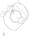
- Figure 1 is a perspective view of the first mode execution.
- Figure 2 is a perspective view similar to that in figure 1 but without the base plate and the covers covering the jaw frames.
- Figure 3 shows one of the jaws in position open and the blocking means located at inside the jaw frame.
- Figure 4 is a top plan view of the fixing without the base plate.
- FIG. 5 is a side view, along arrow V, figure 4.
- Figure 6 is a view of the elements shown in the Figure 4 in direction VI, at the start of the boot.
- Figure 7 is a sectional view along VII-VII of the figure 4.
- Figures 8 and 9 are views similar to the figures 6 and 7, the binding being shown in the position of highest boot with a wedge of snow under the shoe.
- Figures 11 and 12 are views similar to Figures 6 and 7, in a carriageway position in which shoe is at its lowest level, that is to say in the absence of snow or ice on the base plate or under the shoe.
- Figure 13 is a perspective view in a position similar to the position shown in Figures 11 and 12.
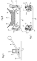
- Figure 14 is a perspective view of the second mode of execution, in the absence of shoe.
- Figure 15 is a view similar to that of Figure 14, but without the base plate or the bearings of the jaws, nor those of the drive devices of the blocking elements.
- Figure 16 is a bottom plan view of the parts shown in Figure 15.
- Figure 17 is a sectional view along XVII-XVII of the Figure 16, in which the shoe, schematically shown, is just in contact with the arms jaw drive.
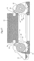
- Figure 18 is a view similar to Figure 16, but after penetration of the locking fingers in the cams.
- Figure 19 is a sectional view along XIX-XIX of the Figure 18, which shoe is shown locked in high position.
- Figure 20 is a plan view similar to the figures 16 and 18, but after full engagement of the fingers of blocking in the cams of the jaws, i.e. in the lowest position of the shoe.
- Figure 21 is a sectional view along XXI-XXI of the figure 20.
- FIG. 22 schematically represents a variant simplified from the first embodiment.
- Figure 23 shows schematically the connection kinematics between the pads of this variant.
- the attachment shown in Figure 1 includes a plate base 1 intended to be fixed on the surfboard, two opposite jaws 2 and 3 mounted on the plate base 1 and covered by a cover 4, respectively 5.
- the binding also includes a release lever 6, the actuation of which releases the jaws which then return to their open position such that shown in Figure 1.
- the jaws being identical, we will just describe the jaw 2 with reference to Figures 2 and 3.
- the jaw 2 is in the form of a part profiled plane, mounted in a frame 7 consisting of a stamped and bent metal part to form a tubular piece provided with two legs 7a and 7b by which the frame is fixed to the base plate 1.
- the jaw 2 is rotatably mounted in the frame 1 at by means of a horizontal axis 8 and it is provided with a return spring 58 tending to bring the jaw in its open position.
- Jaw 2 has an arm drive or pedal 9.
- a cam 10 On one side of the jaw 2 is fixed a cam 10 presenting itself approximately in the form of a circle sector offset extending over 90 °. This cam may well heard coming from one piece with the jaw 2.
- the frame 7 also constitutes a guide for a moving element 11 carrying in its upper part a stud 12 with an axis parallel to the axis of rotation of the jaw and constituting the locking element of the jaw.
- This stud 12 is itself engaged, by its ends, in two opposite grooves or slots 13 and 14 formed in two opposite walls of the frame 7.
- the stud 12 is provided with a radial arm 15 integral with rotation of the stud 12.
- the actuating arm 9 is circumferentially extends by a part 9a in cam shape intended to cooperate with the stud 12 for secure the jaw, as will be described later.
- the arm 15 In the open position of jaws as shown in Figures 2 and 3, the arm 15 is supported by its end on a span 16 of the frame 7 and it is held in this position by the cam 10.
- the moving element 11 has, in its lower part, a curved part 17 around the heaving lever 6 and thus ensures a connection mechanical between the moving element 11 and the lever 6.
- the lever 6 is oblique in the rest position, but crosses part 17 of the moving part via a short horizontal section as we can see at the figure 5. Beyond part 17, lever 6 is extended by a transverse part 18 extending under the base plate 1 to go up on the other side of the opposite jaw 3 where its end is engaged horizontally in the 17 'part of the moving assembly 11 'from the opposite jaw.
- the two mobile crews are thus mechanically and kinematically linked between them. Locking is therefore done simultaneously by the two jaws by the simultaneous descent of the blocking pads 12 and 12 '.
- the link between the party 17 of the moving part and the lever 6 has however a game 19, also present in the part 17 'corresponding to the other jaw. This game allows, in the locked carriageway position, take into account slightly oblique position of the sole of the shoe relative to base plate, position due to snow or ice on one side or unevenly on both sides.
- Figures 5 to 7 show the jaws still in open position, i.e. the same position as that shown in Figures 2 and 3. We see in particular in Figure 7 that the arm 15 'of the jaw 3 abuts against its stop 16 'so that the studs 12 and 12 'are retained at the end of their guidance.
- the body of the jaw 31 is in the form a cylinder 35 provided with a hub 36 for the passage of the pivot axis of the jaw.
- the cylinder 35 has a cam-shaped part consisting of a radial wall 37 projecting radially from the circumference of the cylinder 35.
- This wall 37 has a cutout 38 whose lower side 39 extends practically radially relative to the axis of the body 35 and thus forms a circumferential stop.
- a return spring 59 is mounted on the hub 36, one of which end is hooked to the hub 36 in a known manner.
- the spring 58 tends to keep the jaw in its open position shown in Figures 14 and 15.
- the upper end 53, respectively 53 ', of the radial wall 37, 37 ' constitutes a drive arm for the jaw.
- the finger 40 ' is provided with a second cooperating arm 60 with the upward bent part of the bar 42, as will be described later.
- Bar 42 has two angled ends at an angle right engaged respectively in a drum 44, 44 '. These drums are rotated by springs (not shown) which tend to push the bar 42 in the direction of the jaws, that is to say in arrow direction, figure 15.
- the end of the fingers 40, 40 'on the other hand has a part 47, 47 'of constant width, the length of the part 47 being greater than that of part 47 'of the other finger.
- the binding is also equipped with a heaving 52 allowing to rotate the drum 44 'and with it the bar 42.
- Heaving is done by actuating the lever heaving shoe 52, which has the effect of removing the fingers 40, 40 'back and therefore release the jaws which are raised under the effect of their return springs 59, 59 '.
- the increase in frictional force opposing untimely opening of the binding may well understood to be performed in another way, by friction, hydraulically, by piston or by a viscoelastic material.
- a simplified variant of the first mode of execution is shown diagrammatically in the figures 22 to 24.
- the jaws are identical and we will limit our to describe one of the jaws.
- the jaw 61 in the general shape of a sector of a circle, is articulated around an axis 62 in a stirrup 63.
- the axis 62 passes through the center of the circle corresponding to the circle sector.
- the jaw 61 is stressed elastically in the direction of its opening by a spring surrounding the axis 62.
- the jaw 61 is provided an actuating pedal 64.
- the jaw On the side opposite the pedal 64, the jaw has a domed part in cam shape 65. Above part 65, the jaw has a slightly oblique shoulder 66 in the raised position of the jaw.
- the element of blocking consists here of the horizontal arm cylindrical 67 in the form of a crank 68 (figure 23).
- the blocking element 67 passes through apart the stirrup 63 through two lights 69 analogous to lights 13 and 14 of the first mode execution.
- the locking element 67 is retained by the shoulder 66 of the jaw at the end upper lights 69.
- the shaped room crank 68 and the corresponding piece 68 'on the other jaw are connected to the parallel arms of a piece rigid in U 70, constituting the kinematic connection between the locking elements 67 and 67 ', by a piece link 71 exclusively authorizing the rotation of cranks 68, respectively 68 '.
- the connecting piece is articulated in two opposite points 72 and 73 close of the transverse part, so that the part in U 70 with cranks 68 and 68 'tends to tilt around an axis 74 in a corresponding direction on the descent of the locking elements 67 and 67 '.
- the shoe 20 drives the jaw 61 by its pedal 64 as shown in Figure 24. During this descent, the locking element 67 leaves the shoulder 66 and descends, guided by the lights 69, until it meets cam 65 and blocks the jaw.
- the coupling 71 allows the locking element 67 to follow the shape of the lights 69.
- the lights 69 could be straight and vertical instead to be curved.
Landscapes
- Basic Packing Technique (AREA)
- Clamps And Clips (AREA)
- Footwear And Its Accessory, Manufacturing Method And Apparatuses (AREA)
- Seal Device For Vehicle (AREA)
- Control Of Driving Devices And Active Controlling Of Vehicle (AREA)
- Cleaning Of Streets, Tracks, Or Beaches (AREA)
- Holders For Apparel And Elements Relating To Apparel (AREA)
- Braking Arrangements (AREA)
Applications Claiming Priority (3)
| Application Number | Priority Date | Filing Date | Title |
|---|---|---|---|
| FR9914696A FR2801222B1 (fr) | 1999-11-23 | 1999-11-23 | Fixation automatique de surf de neige |
| FR9914696 | 1999-11-23 | ||
| EP00125210A EP1104685B1 (de) | 1999-11-23 | 2000-11-22 | Automatische Snowboardbindung |
Related Parent Applications (1)
| Application Number | Title | Priority Date | Filing Date |
|---|---|---|---|
| EP00125210A Division EP1104685B1 (de) | 1999-11-23 | 2000-11-22 | Automatische Snowboardbindung |
Publications (4)
| Publication Number | Publication Date |
|---|---|
| EP1464368A2 true EP1464368A2 (de) | 2004-10-06 |
| EP1464368A3 EP1464368A3 (de) | 2004-11-03 |
| EP1464368A9 EP1464368A9 (de) | 2005-02-09 |
| EP1464368B1 EP1464368B1 (de) | 2008-07-23 |
Family
ID=9552415
Family Applications (2)
| Application Number | Title | Priority Date | Filing Date |
|---|---|---|---|
| EP04016080A Expired - Lifetime EP1464368B1 (de) | 1999-11-23 | 2000-11-22 | Automatische Snowboardbindung |
| EP00125210A Expired - Lifetime EP1104685B1 (de) | 1999-11-23 | 2000-11-22 | Automatische Snowboardbindung |
Family Applications After (1)
| Application Number | Title | Priority Date | Filing Date |
|---|---|---|---|
| EP00125210A Expired - Lifetime EP1104685B1 (de) | 1999-11-23 | 2000-11-22 | Automatische Snowboardbindung |
Country Status (5)
| Country | Link |
|---|---|
| US (2) | US6698787B1 (de) |
| EP (2) | EP1464368B1 (de) |
| AT (2) | ATE401942T1 (de) |
| DE (2) | DE60039642D1 (de) |
| FR (1) | FR2801222B1 (de) |
Families Citing this family (7)
| Publication number | Priority date | Publication date | Assignee | Title |
|---|---|---|---|---|
| US6742801B1 (en) * | 1995-01-20 | 2004-06-01 | The Burton Corporation | Snowboard boot binding mechanism |
| FR2808217B1 (fr) | 2000-04-27 | 2002-07-12 | Emery Sa | Fixation automatique de surf a neige |
| FR2808699B1 (fr) | 2000-05-10 | 2002-07-19 | Emery Sa | Fixation automatique de surf a neige |
| US9220970B1 (en) | 2014-11-14 | 2015-12-29 | The Burton Corporation | Snowboard binding and boot |
| EP3218073B1 (de) | 2014-11-14 | 2021-05-19 | The Burton Corporation | Snowboard-bindung |
| US9149711B1 (en) | 2014-11-14 | 2015-10-06 | The Burton Corporation | Snowboard binding and boot |
| US11130045B2 (en) * | 2019-05-24 | 2021-09-28 | Skis Rossignol | Fastening device for fastening a boot to a sliding board |
Citations (5)
| Publication number | Priority date | Publication date | Assignee | Title |
|---|---|---|---|---|
| FR2321912A1 (fr) | 1975-08-28 | 1977-03-25 | Salomon & Fils F | Fixation destinee a retenir une chaussure sur un support, notamment un ski ou une plaque montee sur un ski |
| US4973073A (en) | 1989-03-17 | 1990-11-27 | Raines Mark A | Snowboard binding |
| WO1996026774A2 (en) | 1995-03-02 | 1996-09-06 | Items International, Inc. | Snowboard binding assembly |
| FR2758091A1 (fr) | 1997-01-08 | 1998-07-10 | Burton Corp | Fixation de chaussure sur un monoski |
| US5871226A (en) | 1995-11-30 | 1999-02-16 | Marker Deutschland Gmbh | Binding for snowboards and the like |
Family Cites Families (11)
| Publication number | Priority date | Publication date | Assignee | Title |
|---|---|---|---|---|
| US5722680A (en) * | 1996-05-29 | 1998-03-03 | The Burton Corporation | Step-in snowboard binding |
| US5957479A (en) * | 1995-03-02 | 1999-09-28 | Items International, Inc. | Snowboard binding assembly |
| US6109643A (en) * | 1995-03-02 | 2000-08-29 | Airwalk International Llc | Snowboard binding assembly |
| US5690351A (en) * | 1995-07-21 | 1997-11-25 | Karol; Chris | Snowboard binding system |
| FR2742997B1 (fr) * | 1996-01-03 | 1998-03-13 | Rossignol Sa | Perfectionnement pour dispositif de retenue d'une chaussure a une planche de glisse pour neige |
| FR2745192A1 (fr) * | 1996-02-27 | 1997-08-29 | Salomon Sa | Dispositif de retenue d'une chaussure sur une planche de glisse. |
| US6053524A (en) | 1997-01-08 | 2000-04-25 | The Burton Corporation | Method and apparatus for indicating when a snowboard binding is locked |
| AUPO954697A0 (en) * | 1997-09-30 | 1997-10-23 | Powder Design Pty. Ltd. | Snowboard safety release binding |
| US6523852B2 (en) * | 1999-11-23 | 2003-02-25 | Emery S.A. | Step-in snowboard binding |
| FR2801802B1 (fr) * | 1999-12-06 | 2002-06-21 | Rossignol Sa | Fixation de ski de fond |
| US6722688B2 (en) * | 2001-11-21 | 2004-04-20 | The Burton Corporation | Snowboard binding system |
-
1999
- 1999-11-23 FR FR9914696A patent/FR2801222B1/fr not_active Expired - Fee Related
-
2000
- 2000-11-21 US US09/718,045 patent/US6698787B1/en not_active Expired - Fee Related
- 2000-11-22 AT AT04016080T patent/ATE401942T1/de not_active IP Right Cessation
- 2000-11-22 AT AT00125210T patent/ATE305329T1/de not_active IP Right Cessation
- 2000-11-22 EP EP04016080A patent/EP1464368B1/de not_active Expired - Lifetime
- 2000-11-22 DE DE60039642T patent/DE60039642D1/de not_active Expired - Fee Related
- 2000-11-22 EP EP00125210A patent/EP1104685B1/de not_active Expired - Lifetime
- 2000-11-22 DE DE60022844T patent/DE60022844T2/de not_active Expired - Fee Related
-
2003
- 2003-03-13 US US10/386,519 patent/US6896285B2/en not_active Expired - Fee Related
Patent Citations (5)
| Publication number | Priority date | Publication date | Assignee | Title |
|---|---|---|---|---|
| FR2321912A1 (fr) | 1975-08-28 | 1977-03-25 | Salomon & Fils F | Fixation destinee a retenir une chaussure sur un support, notamment un ski ou une plaque montee sur un ski |
| US4973073A (en) | 1989-03-17 | 1990-11-27 | Raines Mark A | Snowboard binding |
| WO1996026774A2 (en) | 1995-03-02 | 1996-09-06 | Items International, Inc. | Snowboard binding assembly |
| US5871226A (en) | 1995-11-30 | 1999-02-16 | Marker Deutschland Gmbh | Binding for snowboards and the like |
| FR2758091A1 (fr) | 1997-01-08 | 1998-07-10 | Burton Corp | Fixation de chaussure sur un monoski |
Also Published As
| Publication number | Publication date |
|---|---|
| DE60039642D1 (de) | 2008-09-04 |
| ATE305329T1 (de) | 2005-10-15 |
| EP1464368A9 (de) | 2005-02-09 |
| EP1104685B1 (de) | 2005-09-28 |
| FR2801222A1 (fr) | 2001-05-25 |
| DE60022844D1 (de) | 2005-11-03 |
| DE60022844T2 (de) | 2006-06-29 |
| US6698787B1 (en) | 2004-03-02 |
| US20040017063A1 (en) | 2004-01-29 |
| EP1464368A3 (de) | 2004-11-03 |
| US6896285B2 (en) | 2005-05-24 |
| EP1104685A1 (de) | 2001-06-06 |
| ATE401942T1 (de) | 2008-08-15 |
| FR2801222B1 (fr) | 2002-01-11 |
| EP1464368B1 (de) | 2008-07-23 |
Similar Documents
| Publication | Publication Date | Title |
|---|---|---|
| EP1702658B1 (de) | Bindung mit einem doppelten Betätigungssystem | |
| FR2719230A1 (fr) | Dispositif de fixation d'une chaussure à un ski de fond. | |
| FR2477991A1 (fr) | Dispositif de fixation d'une ferrure reglable dans differentes positions, en particulier d'une ferrure pour sieges de vehicule | |
| CH645030A5 (fr) | Fixation de securite d'une chaussure sur un ski et chaussure de ski pour cette fixation. | |
| FR2753107A1 (fr) | Patin a roulettes en ligne a chaussure amovible | |
| FR2482864A1 (fr) | Fixation de securite de ski | |
| EP3345660A1 (de) | Anschlag für fixierungsvorrichtung eines schuhs | |
| EP1104685B1 (de) | Automatische Snowboardbindung | |
| FR2739572A1 (fr) | Embase de fixation de ski reglable longitudinalement | |
| FR2465498A1 (fr) | Element formant machoire avant ou arriere pour une fixation de ski | |
| EP1106218A1 (de) | Langlaufski | |
| FR2500313A1 (fr) | Dispositif de retenue de talon combine a un frein de ski | |
| FR2722420A1 (fr) | Fixation pour une planche a neige | |
| EP1526900A2 (de) | Bindung mit integrierten einhaksystem | |
| CH658998A5 (fr) | Frein de ski. | |
| FR2470619A1 (fr) | Retenue de semelle ou de talon pour fixations de ski | |
| FR2613949A1 (fr) | Dispositif de fixation de ski a chaussage automatique | |
| EP4393559B1 (de) | Skibremse | |
| CH619144A5 (de) | ||
| FR2694782A1 (fr) | Loquet basculant pour vantail. | |
| FR3072884A1 (fr) | Butee de dispositif de fixation d'une chaussure | |
| EP1025882A1 (de) | Sicherheitsskibindung-Schuh-Kombination | |
| FR2803768A1 (fr) | Fixation automatique de surf a neige | |
| CH658397A5 (fr) | Fixation de securite d'un ski. | |
| FR2708429A1 (fr) | Dispositif de fermeture d'une tige de chaussure de ski. |
Legal Events
| Date | Code | Title | Description |
|---|---|---|---|
| PUAI | Public reference made under article 153(3) epc to a published international application that has entered the european phase |
Free format text: ORIGINAL CODE: 0009012 |
|
| PUAL | Search report despatched |
Free format text: ORIGINAL CODE: 0009013 |
|
| 17P | Request for examination filed |
Effective date: 20040708 |
|
| AC | Divisional application: reference to earlier application |
Ref document number: 1104685 Country of ref document: EP Kind code of ref document: P |
|
| AK | Designated contracting states |
Kind code of ref document: A2 Designated state(s): AT DE DK FR IT |
|
| AK | Designated contracting states |
Kind code of ref document: A3 Designated state(s): AT DE DK FR IT |
|
| RIN1 | Information on inventor provided before grant (corrected) |
Inventor name: GIGNOUX, PIERRE Inventor name: PLASSIARD, ALAIN |
|
| 17Q | First examination report despatched |
Effective date: 20050304 |
|
| RAP1 | Party data changed (applicant data changed or rights of an application transferred) |
Owner name: SKIS ROSSIGNOL S.A. |
|
| AKX | Designation fees paid |
Designated state(s): AT DE FR IT |
|
| GRAP | Despatch of communication of intention to grant a patent |
Free format text: ORIGINAL CODE: EPIDOSNIGR1 |
|
| GRAS | Grant fee paid |
Free format text: ORIGINAL CODE: EPIDOSNIGR3 |
|
| GRAA | (expected) grant |
Free format text: ORIGINAL CODE: 0009210 |
|
| AC | Divisional application: reference to earlier application |
Ref document number: 1104685 Country of ref document: EP Kind code of ref document: P |
|
| AK | Designated contracting states |
Kind code of ref document: B1 Designated state(s): AT DE FR IT |
|
| REF | Corresponds to: |
Ref document number: 60039642 Country of ref document: DE Date of ref document: 20080904 Kind code of ref document: P |
|
| PGFP | Annual fee paid to national office [announced via postgrant information from national office to epo] |
Ref country code: DE Payment date: 20081128 Year of fee payment: 9 |
|
| PG25 | Lapsed in a contracting state [announced via postgrant information from national office to epo] |
Ref country code: AT Free format text: LAPSE BECAUSE OF FAILURE TO SUBMIT A TRANSLATION OF THE DESCRIPTION OR TO PAY THE FEE WITHIN THE PRESCRIBED TIME-LIMIT Effective date: 20080723 |
|
| PLBE | No opposition filed within time limit |
Free format text: ORIGINAL CODE: 0009261 |
|
| STAA | Information on the status of an ep patent application or granted ep patent |
Free format text: STATUS: NO OPPOSITION FILED WITHIN TIME LIMIT |
|
| 26N | No opposition filed |
Effective date: 20090424 |
|
| PG25 | Lapsed in a contracting state [announced via postgrant information from national office to epo] |
Ref country code: IT Free format text: LAPSE BECAUSE OF NON-PAYMENT OF DUE FEES Effective date: 20081122 |
|
| REG | Reference to a national code |
Ref country code: FR Ref legal event code: ST Effective date: 20090731 |
|
| PG25 | Lapsed in a contracting state [announced via postgrant information from national office to epo] |
Ref country code: DE Free format text: LAPSE BECAUSE OF NON-PAYMENT OF DUE FEES Effective date: 20100601 |
|
| PG25 | Lapsed in a contracting state [announced via postgrant information from national office to epo] |
Ref country code: FR Free format text: LAPSE BECAUSE OF NON-PAYMENT OF DUE FEES Effective date: 20081130 |