EP1464453A2 - Verfahren und Gerät zum Krümmungsausgleich eines Roboters - Google Patents
Verfahren und Gerät zum Krümmungsausgleich eines Roboters Download PDFInfo
- Publication number
- EP1464453A2 EP1464453A2 EP04251856A EP04251856A EP1464453A2 EP 1464453 A2 EP1464453 A2 EP 1464453A2 EP 04251856 A EP04251856 A EP 04251856A EP 04251856 A EP04251856 A EP 04251856A EP 1464453 A2 EP1464453 A2 EP 1464453A2
- Authority
- EP
- European Patent Office
- Prior art keywords
- flexure
- robot
- orientation
- amounts
- flexure amount
- Prior art date
- Legal status (The legal status is an assumption and is not a legal conclusion. Google has not performed a legal analysis and makes no representation as to the accuracy of the status listed.)
- Withdrawn
Links
Images


Classifications
-
- B—PERFORMING OPERATIONS; TRANSPORTING
- B25—HAND TOOLS; PORTABLE POWER-DRIVEN TOOLS; MANIPULATORS
- B25J—MANIPULATORS; CHAMBERS PROVIDED WITH MANIPULATION DEVICES
- B25J9/00—Program-controlled manipulators
- B25J9/16—Program controls
- B25J9/1628—Program controls characterised by the control loop
- B25J9/1638—Program controls characterised by the control loop compensation for arm bending/inertia, pay load weight/inertia
Definitions
- the present invention relates to correction of deviation of an operational position/orientation of a robot designated by an operation program due to flexure of the robot.
- An industrial robot performs various kinds of operations with appropriate one of various kinds of tools attached to a wrist at a distal end of a robot mechanism.
- a position/orientation of the wrist deviates by flexure of the robot mechanism such as displacement of joints and elastic deformation of arms.
- a command designating a target position/orientation is given to the robot mechanism, and the robot mechanism moves to take the target position and orientation.
- the amount and direction of flexure of the robot mechanism varies depending on the designated position and orientation. In a method in which an operational position/orientation is taught by actually operating a robot, the position including the flexure amount is taught, so that problem is scarcely caused.
- a robot operating area is divided according to a lattice formed of equally spaced lines, and a joint angle correction amount at each lattice point coordinates is measured in advance and stored as a representative-point angle correction amount table.
- An angle correction amount for a target arm position and orientation is obtained by interpolation using data stored as joint angel correction amounts at eight lattice points close to the target arm position. Using the obtained angle correction amount, the target joint angle is corrected (see JP 2002-219674A).
- the method creating and using models as shown in the above-mentioned JP 2002-307344A and JP 7-276273A has a problem that model creation errors and parameter definition errors lower the accuracy of correction.
- the method shown in JP 2002-219674A is free from model creation errors.
- the angle correction amounts for each shaft are affected by solid mechanical part errors (arm length errors, attachment angle errors, joint errors and the like) of individual robots, the angle correction amounts for each shaft are data peculiar to individual robots.
- the present invention provides flexure correction device and method capable of performing flexure amount correction of taught points easily and automatically.
- a flexure correction device of the present invention corrects deviation in position and/or orientation of a distal end of an arm due to flexure of a robot.
- the flexure correction device comprises: reference flexure amount storage means storing a plurality of reference flexure amounts representing deviations in position and/or orientation of the distal end of the arm, which are measured at a plurality of positions in a robot operating area under a plurality of load conditions different in weight and/or position of center of gravity; designating means for designating one or more reference flexure amounts to be used in the plurality of stored reference flexure amounts; flexure amount calculation means for obtaining a flexure amount for each position of taught points in a robot operation program based on the designated reference flexure amounts; and correction means for correcting position/orientation at each of the taught points based on the calculated flexure amount, to thereby eliminate deviation in position and/or orientation at each of the taught points due to flexure of the robot.
- the flexure amount storage means storing a pluralit
- the flexure correction device comprises: reference flexure-amount data storage means storing a plurality of reference flexure amounts representing deviations in position and/or orientation of the distal end of the arm, which are measured at a plurality of positions in a robot operating area under a plurality of load conditions different in weight and/or position of center of gravity; designation means for designating one or more reference flexure amounts to be used in the plurality of stored reference flexure amounts; flexure amount calculation means for calculating a flexure amount for each of taught points and interpolation points based on the designated flexure amount in performing playback of a robot operation program; and correction means for correcting position/orientation at each the taught points and interpolation points based on the calculated flexure amount.
- correction of position/orientation is also performed on the interpolation points by a robot controller.
- a flexure correction method of the present invention corrects deviation in position and/or orientation of a distal end of an arm due to flexure of a robot using an off-line programming apparatus or a robot controller.
- the method comprises the steps of: measuring flexure amounts representing deviations in position and/or orientation of the distal end of the arm at a plurality of positions in a robot operating area for each of a plurality of load conditions different in weight and/or position of center of gravity, and storing the measured flexure amounts in storage means as reference flexure amounts; selecting and designating one or more of the plurality of reference flexure amounts stored in the storage means in accordance with weight and/or position of center of gravity of a tool to be used; calculating a flexure amount for each of taught points in a robot operation program based on the designated reference flexure amounts using the off-line programming apparatus or the robot controller; and correcting position/orientation at each of the taught points based on the calculated flexure amount.
- the flexure correction method may comprise the steps of: measuring flexure amounts representing deviations in position and/or orientation of the distal end of the arm at a plurality of positions in a robot operating area for each of a plurality of load conditions different in weight and/or position of center of gravity, and storing the measured flexure amounts in storage means as reference flexure amounts; selecting and designating one or more of the plurality of reference flexure amounts stored in the storage means in accordance with weight and/or position of center of gravity of a tool to be used; calculating a flexure amount for each of taught points and interpolation points based on the selected reference flexure amounts in a playback operation of a robot operation program; and correcting position/orientation at each of the taught points and interpolation points based on the calculated flexure amount.
- flexure amounts representing deviations in position and orientation of a robot arm front end wrist are measured to obtain flexure amount data for correction.
- an operating area of a robot is divided according to a lattice, and a flexure amount is measured at each lattice point, each time a robot wrist orientation is changed by a predetermined amount.
- the measured flexure amount consists of a flexure amount (Txi, Tyi, Tzi) with reference to an orthogonal coordinate system X-Y-Z and a wrist orientation flexure amount (Twi, Tpi, Tri).
- flexure amounts of deviation of a robot front end position are measured as flexure amounts for each of loads attached to the robot mechanism front end wrist that are different in weight and center-of-gravity position. Flexure amount data is obtained this way. When it is anticipated what types of working tools will be attached to the robot mechanism front end wrist of a certain model of robot, flexure amounts may be measured with each of those working tools attached to the wrist.
- each lattice point position and a plurality of wrist orientations at each lattice point position are given by instructions.
- the robot is set at each of the given positions, where the three-dimensional position of a tool center point of the robot arm front end part and each of the plurality of wrist orientations are measured with a three-dimensional measuring apparatus.
- a difference between the position and orientation given by an instruction and the measured position and orientation is obtained as a flexure amount (Txi, Tyi, Tzi, Twi, Tpi, Tri).
- this measurement of flexure amounts is performed for each of loads attached to a robot wrist flange that are different in weight and center-of-gravity position. It is also possible to measure flexure amounts about a plurality of robots of the same model and obtain average flexure amounts as flexure amounts for that model.
- FIG. 4 is an illustration for explaining flexure amount data stored in a storage medium.
- a flexure amount (Tx, Ty, Tz, Tw, Tp, Tr) is measured and stored for each of tool weights W1 to Wn, for each of tool centers of gravity (X1, Y1, Z1), and for each of a plurality of orientations (w, p, r) at each robot position (x, y, z).
- Flexure amount data only needs to be created once for each robot model.
- a robot maker or the like measures a flexure amount for each weight, for each center-of-gravity position, and for each robot position and orientation, in advance, stores the obtained flexure amounts in a storage medium such as a flexible disk or a compact disk as flexure amount data as shown in FIG. 4, and ships robots with this flexure amount data. From the stored flexure amount data, a user selects and uses flexure amount data corresponding to a working tool to be used.
- flexure amount correction is automatically performed on taught point positions (and orientations) designated by the operation program and also on interpolation positions, by the off-line programming apparatus or a robot controller, using the flexure amount data.
- FIG. 1 is a functional block diagram of a flexure correction device (an off-line programming apparatus or a robot controller) for performing this flexure amount correction method.
- flexure amount data 1-1 to 1-m a flexure amount data file containing flexure amounts for the model of a robot to be used and for the load which is closest in weight and center-of-gravity position to a working tool to be used is selected and designated with flexure amount data designation means 3.
- operation programs 2-1 to 2-n an operation program to be used is selected and designated with operation program designation means 4.
- flexure amount calculation means 5 calculates a flexure amount for each of the taught point positions (and orientations) taught by the designated operation program.
- a flexure amount for each of the taught point positions on the basis of the flexure amount data. For example, provided that a taught point position and orientation designated by an operation program is (xa, ya, za, wa, pa, ra), a position (x, y, Z) closest to the taught point position (xa, ya, za) is selected from the flexure amount data. Then, from a plurality of orientations stored as orientations at the position (x, y, z), an orientation (w, p, r) closest to the orientation (wa, pa, ra) at the taught point position is selected.
- a flexure amount (Tx, Ty, Tz, Tw, Tp, Tr) stored as corresponding to the selected position and orientation (x, y, z, w, p, r) is obtained as a flexure amount for the taught point.
- a flexure amount for each taught point by interpolation. For example, two positions (xi, yi, zi) and (xj, yj, zj) close to the taught point position (xa, ya, za) are selected from the flexure amount data. Then, for each of these two positions, from a plurality of orientations stored as orientations at that position, an orientation closest to the orientation (wa, pa, ra) at the taught point is selected.
- Flexure amounts (Txi, Tyi, Tzi, Twi, Tpi, Tri) and (Txj, Tyj, Tzj, Twj, Tpj, Trj) stored as corresponding to the selected two positions and orientations are obtained, and an average of these two flexure amounts is obtained as a flexure amount for the taught point.
- Flexure amount for taught point [(Txi+Txj)/2, (Tyi+Tyj)/2, (Tzi+Tzj)/2, (Twi+Twj)/2, (Tpi+Tpj)/2, (Tri+Trj)/2].
- a flexure amount for a taught point by interpolation using flexure amounts at eight lattice point positions surrounding the taught point.
- the robot operating space is divided according to a lattice, and flexure amounts at each lattice point are stored as flexure amount data.
- the taught point position (xa, ya, za) is surrounded by eight lattice points. For each of these eight lattice point positions, from a plurality of orientations stored as orientations at that lattice point position, an orientation closest to the orientation (wa, pa, ra) at the taught point is selected.
- flexure amounts stored as corresponding to these eight positions and orientations are obtained, and a flexure amount (Tx, Ty, Tz, Tw, Tp, Tr) for the taught point is obtained from these eight flexure amounts by interpolation.
- each taught point position designated by the operation program is corrected by adding to the taught point position a correction amount that is equal in magnitude and opposite in direction to the obtained flexure amount. All the taught point positions taught by the operation program are corrected this way, and the operation program corrected in view of flexure is fed.
- FIG. 2 is a block diagram showing relevant parts of an off-line programming apparatus as an embodiment of a flexure correction device for performing a flexure correction method according to the invention.
- ROM 12 read-only memory
- RAM 13 nonvolatile RAM 14
- disk driver 15 a display/MDI 16
- communication interface a communication interface
- the processor 11 controls the whole apparatus according to system programs stored in the ROM 12.
- the RAM 13 is used for temporarily storing data, for example.
- the nonvolatile RAM 14 are stored, for example robot operation programs generated by the off line programming apparatus.
- the disk driver 15 reads flexure amount data from a flexible disk 19. As stated above, a robot machine maker or the like measures flexure amounts for each robot model and for each of loads that are different in tool weight and center-of-gravity position. In the flexible disk 19 are stored flexure amounts obtained this way, as flexure amount data.
- the display/MDI 16 includes a display such as a CRT display or a liquid crystal display, and manual data input means such as a keyboard or a mouse for entering data and various instructions.
- the communication interface 17 is connected to a robot controller by a communication line such as Ethernet (registered trademark).
- flexure amount data is supposed to be stored in the flexible disk 19 as a storage medium.
- the disk driver 15 is a CD driver that reads flexure amount data from the compact disk.
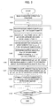
- FIG. 3 is a flow chart showing the process of flexure correction in this embodiment, where flexure amount correction is performed on each of taught point positions taught by a robot operation program.
- a flexible disk 19 storing flexure amount data for the model of a robot to be used is set on the disk driver 15. From the flexure amount data stored in the flexible disk 19, flexure amount data about a load that is closest in weight and center-of-gravity position to a working tool attached to the robot to be used is selected and designated by manipulating the display/MDI 16. Then, from the operation programs stored in the nonvolatile RAM 14, an operation program about which flexure amount correction should be performed to operate the robot is selected and designated. Then, when a flexure amount correction instruction is entered, the processor 11 starts the process shown in FIG. 3.
- Step 100 the designated operation program is read (Step 100), an index i is set at "1" (Step 101), and an ith taught point position Pi(xi, yi, zi) indicated by the index is read (Step 102). From the designated flexure amount data, a lattice point position Q0 closest to this taught point position is obtained (Step 103).
- an orientation that is closest to the robot wrist orientation (w, p, r) at the taught point position Pi, of a plurality of robot wrist orientations stored as the robot wrist orientations at the lattice point position Q0 is obtained.
- an angle ⁇ p at which the robot wrist orientation (w, p, r) at the taught point position Pi is inclined from a reference orientation is obtained (Step 104)
- angles ⁇ q1 to ⁇ qn at which the robot wrist orientations (w, p, r) stored as those at the selected lattice point position Q0 are inclined from the reference orientation are obtained (Step 105)
- the wrist orientation (w0, p0, r0) having an angle closest to the angle ⁇ of the orientation at the taught point position Pi is selected (Step 106).
- a flexure amount (Txk, Tyk, Tzk, Twk, Tpk, Trk) corresponding to the obtained lattice point position and orientation (x0, y0, z0, w0, p0, r0) is obtained from the flexure amount data (Step 107).
- Step 102 is taken again and the process subsequent to Step 102 is performed on the taught point indicated by the index i so that flexure amount correction will be performed and the taught point position/orientation will be replaced with a corrected one.
- the process is terminated when the flexure amount correction has been performed on all the taught points and all the taught point positions/orientations have been replaced with corrected ones.
- the flexure correction device is formed by adding a flexure correction function to the off-line programming apparatus.
- the robot controller itself may be formed to function as a flexure correction device.
- the flexure correction device when the flexure correction device is constituted by the off-line programming apparatus, when the flexure correction device is constituted by the robot controller, it may be arranged as follows: First, flexure amount data about the model of a robot to be used and corresponding to the weight and center-of-gravity position of a tool to be used is selected and designated. Then, before the robot executes an operation program to be executed, the robot controller executes the process shown in FIG. 3 to obtain the operation program with taught points each corrected by an amount corresponding to the flexure amount. Then, the robot executes this operation program.
- flexure amount correction is performed on the operation program. Specifically, when the next taught point is read from the operation program, the above-described process is performed to obtain a flexure amount for that taught point and correct the taught point position/orientation by an amount corresponding to the flexure amount. Then, interpolation is performed for moving the robot to the corrected taught point position/orientation, and the robot shafts are driven.
- flexure amount correction is performed on a position (and orientation) obtained by interpolation.
- flexure amount correction like the above-described is performed on an interpolation point position relative to the taught point position obtained by interpolation.
- a motion command is given to the robot axes on the basis of the corrected interpolation point position. This is performed on each interpolation point position.
- a flexure amount for the taught point is obtained, the taught point position/orientation is corrected by an amount corresponding to the flexure amount, and the robot is moved to the corrected taught point position/orientation.
- interpolation for obtaining an interpolation point position is performed on the basis of the taught point position not corrected. Flexure correction is performed on the interpolation point position obtained this way, and a motion command is given on the basis of the corrected interpolation point position.
- flexure amounts measured for each of robot models and for each of loads corresponding to working tools in weight and center-of-gravity position are stored in a storage medium as flexure amount data, and flexure amount data about the model of a robot to be used and about the load closest in weight and center-of-gravity position to a working tool to be used is selected.
- flexure amount data may be created with the working tool attached to the robot.
- the flexure amount data thus obtained with the working tool attached is used.
- flexure amount data only needs to be created once in one lump by a robot maker or the like.
- each of taught point positions/orientations designated by a robot operation program can be automatically corrected, only by selecting and designating flexure amount data about the model of the used robot and about the load that is equal or close in weight and center-of-gravity position to a tool used with the robot.
- correction of operation programs generated by the off-line programming apparatus can be performed very easily.
Landscapes
- Engineering & Computer Science (AREA)
- Robotics (AREA)
- Mechanical Engineering (AREA)
- Numerical Control (AREA)
- Manipulator (AREA)
Applications Claiming Priority (2)
| Application Number | Priority Date | Filing Date | Title |
|---|---|---|---|
| JP2003096574A JP2004299010A (ja) | 2003-03-31 | 2003-03-31 | ロボットのたわみ補正装置及びたわみ補正方法 |
| JP2003096574 | 2003-03-31 |
Publications (1)
| Publication Number | Publication Date |
|---|---|
| EP1464453A2 true EP1464453A2 (de) | 2004-10-06 |
Family
ID=32844649
Family Applications (1)
| Application Number | Title | Priority Date | Filing Date |
|---|---|---|---|
| EP04251856A Withdrawn EP1464453A2 (de) | 2003-03-31 | 2004-03-29 | Verfahren und Gerät zum Krümmungsausgleich eines Roboters |
Country Status (3)
| Country | Link |
|---|---|
| US (1) | US20040193293A1 (de) |
| EP (1) | EP1464453A2 (de) |
| JP (1) | JP2004299010A (de) |
Cited By (4)
| Publication number | Priority date | Publication date | Assignee | Title |
|---|---|---|---|---|
| WO2006117022A1 (en) * | 2005-05-02 | 2006-11-09 | Abb Research Ltd | A method for control of an industrial robot |
| EP2272637A2 (de) | 2009-07-08 | 2011-01-12 | KUKA Roboter GmbH | Verfahren und eine Vorrichtung zum Betreiben eines Manipulators |
| EP2431136A3 (de) * | 2010-09-15 | 2014-07-30 | Walter Maschinenbau GmbH | Verfahren zum Betreiben einer Greifeinrichtung |
| CN108584703A (zh) * | 2018-07-18 | 2018-09-28 | 安徽工业大学 | 双梁桥式起重机吊重及主梁挠度在线测量系统及其测量方法 |
Families Citing this family (20)
| Publication number | Priority date | Publication date | Assignee | Title |
|---|---|---|---|---|
| US9110456B2 (en) * | 2004-09-08 | 2015-08-18 | Abb Research Ltd. | Robotic machining with a flexible manipulator |
| JP5009522B2 (ja) * | 2005-11-28 | 2012-08-22 | リンテック株式会社 | 搬送装置 |
| JP2010231575A (ja) * | 2009-03-27 | 2010-10-14 | Kobe Steel Ltd | ロボットのオフライン教示装置、ロボットのオフライン教示方法、及びロボットシステム |
| JP5509013B2 (ja) * | 2010-09-17 | 2014-06-04 | 株式会社ミツトヨ | 三次元測定機の測定データ補正方法および三次元測定機 |
| JP2011173234A (ja) * | 2011-01-15 | 2011-09-08 | Ken Kobayashi | 工作機械の制御方法 |
| JP6545472B2 (ja) * | 2015-01-27 | 2019-07-17 | 蛇の目ミシン工業株式会社 | ロボット |
| KR101962889B1 (ko) * | 2015-07-27 | 2019-03-28 | 한국전자통신연구원 | 작업환경 변화에 적응적인 로봇 동작 데이터 제공장치 및 그 방법 |
| JP6576824B2 (ja) * | 2015-12-25 | 2019-09-18 | 株式会社ダイヘン | ロボット制御装置 |
| JP6386501B2 (ja) * | 2016-08-12 | 2018-09-05 | ファナック株式会社 | レーザ加工ロボットシステム及びレーザ加工方法 |
| US10651067B2 (en) * | 2017-01-26 | 2020-05-12 | Brooks Automation, Inc. | Method and apparatus for substrate transport apparatus position compensation |
| JP6743723B2 (ja) * | 2017-02-16 | 2020-08-19 | トヨタ自動車株式会社 | ロボットの教示データ補正方法 |
| JP7436181B2 (ja) * | 2019-11-08 | 2024-02-21 | ファナック株式会社 | たわみ量算出装置及びプログラム |
| JP7556951B2 (ja) * | 2020-05-11 | 2024-09-26 | ファナック株式会社 | プログラム生成装置およびプログラム生成方法 |
| JP7513721B2 (ja) * | 2020-07-29 | 2024-07-09 | 株式会社Fuji | スカラロボットシステム |
| CN114764241B (zh) * | 2021-01-14 | 2025-02-18 | 腾讯科技(深圳)有限公司 | 运动状态的控制方法、装置、设备及可读存储介质 |
| JP7696284B2 (ja) * | 2021-12-10 | 2025-06-20 | 株式会社ブリヂストン | シフト量制御システム、シフト量制御方法及びプログラム |
| JP2024007104A (ja) * | 2022-07-05 | 2024-01-18 | 川崎重工業株式会社 | ロボットシステム、ロボット制御方法及びロボット制御プログラム |
| CN115091464B (zh) * | 2022-07-22 | 2024-10-01 | 西安理工大学 | 机械臂关节刚度参数的识别方法 |
| CN115042189B (zh) * | 2022-07-22 | 2024-10-01 | 西安理工大学 | 机械臂参数误差识别及补偿方法 |
| JP2025037380A (ja) * | 2023-09-06 | 2025-03-18 | 株式会社不二越 | ロボット溶接システム及びロボット溶接制御装置 |
Family Cites Families (6)
| Publication number | Priority date | Publication date | Assignee | Title |
|---|---|---|---|---|
| JP2786225B2 (ja) * | 1989-02-01 | 1998-08-13 | 株式会社日立製作所 | 工業用ロボットの制御方法及び装置 |
| US5297238A (en) * | 1991-08-30 | 1994-03-22 | Cimetrix Incorporated | Robot end-effector terminal control frame (TCF) calibration method and device |
| WO2000025185A1 (en) * | 1998-10-27 | 2000-05-04 | Irobotics, Inc. | Robotic process planning using templates |
| US7092860B1 (en) * | 1999-02-03 | 2006-08-15 | Mitutoyo Corporation | Hardware simulation systems and methods for vision inspection systems |
| IT1313346B1 (it) * | 1999-09-06 | 2002-07-23 | Abb Ricerca Spa | Metodo per eseguire la programmazione fuori linea di un robotindustriale. |
| US6662082B2 (en) * | 2000-08-25 | 2003-12-09 | Janome Sewing Machine Co., Ltd. | System for operating a robot with easy programming |
-
2003
- 2003-03-31 JP JP2003096574A patent/JP2004299010A/ja active Pending
-
2004
- 2004-03-26 US US10/809,373 patent/US20040193293A1/en not_active Abandoned
- 2004-03-29 EP EP04251856A patent/EP1464453A2/de not_active Withdrawn
Cited By (7)
| Publication number | Priority date | Publication date | Assignee | Title |
|---|---|---|---|---|
| WO2006117022A1 (en) * | 2005-05-02 | 2006-11-09 | Abb Research Ltd | A method for control of an industrial robot |
| EP2272637A2 (de) | 2009-07-08 | 2011-01-12 | KUKA Roboter GmbH | Verfahren und eine Vorrichtung zum Betreiben eines Manipulators |
| DE102009032278A1 (de) | 2009-07-08 | 2011-01-13 | Kuka Roboter Gmbh | Verfahren und eine Vorrichtung zum Betreiben eines Manipulators |
| US8406921B2 (en) | 2009-07-08 | 2013-03-26 | Kuka Roboter Gmbh | Method and device for controlling a manipulator |
| DE102009032278B4 (de) * | 2009-07-08 | 2021-03-04 | Kuka Roboter Gmbh | Verfahren und eine Vorrichtung zum Betreiben eines Manipulators |
| EP2431136A3 (de) * | 2010-09-15 | 2014-07-30 | Walter Maschinenbau GmbH | Verfahren zum Betreiben einer Greifeinrichtung |
| CN108584703A (zh) * | 2018-07-18 | 2018-09-28 | 安徽工业大学 | 双梁桥式起重机吊重及主梁挠度在线测量系统及其测量方法 |
Also Published As
| Publication number | Publication date |
|---|---|
| JP2004299010A (ja) | 2004-10-28 |
| US20040193293A1 (en) | 2004-09-30 |
Similar Documents
| Publication | Publication Date | Title |
|---|---|---|
| EP1464453A2 (de) | Verfahren und Gerät zum Krümmungsausgleich eines Roboters | |
| EP2381325B1 (de) | Verfahren zur Offline-Programmierung eines Roboters | |
| US7912584B2 (en) | Power consumption estimation apparatus | |
| US9156164B2 (en) | Method for adjusting parameters of impedance control | |
| US6826450B2 (en) | Robot controller | |
| EP1533671B1 (de) | Vorrichtung zur Korrektur einer gelernten Position | |
| US8406921B2 (en) | Method and device for controlling a manipulator | |
| CN113365785B (zh) | 校准工业机器人的工具的方法、控制系统和工业机器人 | |
| JP2021098268A (ja) | 駆動装置、ロボット装置、物品の製造方法、制御方法、制御プログラム、記録媒体 | |
| CN111546334B (zh) | 一种减小轮廓误差的工业机器人在线位姿误差补偿方法 | |
| EP0519081B1 (de) | Verfahren zum korrigieren der abbiegung eines roboters | |
| KR20100116545A (ko) | 매니퓰레이터를 조절하기 위한 방법 및 장치 | |
| JPH11502776A (ja) | 多軸工業ロボットの較正の装置と方法 | |
| EP2404712A1 (de) | Roboter mit zwei Armen und Verfahren zum Steuern eines Roboters mit zwei Armen | |
| US10507585B2 (en) | Robot system that displays speed | |
| KR20100089031A (ko) | 매니퓰레이터용 제어 디바이스 및 방법 | |
| JP2021059012A (ja) | 情報処理装置、情報処理方法及びロボットシステム | |
| JP2019123073A (ja) | ロボットシステム、ロボットアームの制御方法、プログラム、記録媒体、及び物品の製造方法 | |
| EP1671759B1 (de) | Robotersteuerung und Verfahren zur Robotersteuerung | |
| JP2001092511A (ja) | ロボットなどの制御ゲイン調整装置 | |
| JP2007066001A (ja) | ロボットの制御装置 | |
| CN121548486A (zh) | 控制装置、参数校正方法以及程序 | |
| JP7534440B2 (ja) | 指令値補正装置及びロボットシステム | |
| KR20230046333A (ko) | 강성 모델과 절삭력 모델을 이용한 로봇 제어 방법 및 장치 | |
| JP2001018182A (ja) | ロボット機構較正演算方法及びシステム |
Legal Events
| Date | Code | Title | Description |
|---|---|---|---|
| PUAI | Public reference made under article 153(3) epc to a published international application that has entered the european phase |
Free format text: ORIGINAL CODE: 0009012 |
|
| AK | Designated contracting states |
Kind code of ref document: A2 Designated state(s): AT BE BG CH CY CZ DE DK EE ES FI FR GB GR HU IE IT LI LU MC NL PL PT RO SE SI SK TR |
|
| AX | Request for extension of the european patent |
Extension state: AL LT LV MK |
|
| STAA | Information on the status of an ep patent application or granted ep patent |
Free format text: STATUS: THE APPLICATION HAS BEEN WITHDRAWN |
|
| 18W | Application withdrawn |
Effective date: 20070430 |