EP1464488A2 - Entraínements d'une unité d'impression - Google Patents
Entraínements d'une unité d'impression Download PDFInfo
- Publication number
- EP1464488A2 EP1464488A2 EP04100557A EP04100557A EP1464488A2 EP 1464488 A2 EP1464488 A2 EP 1464488A2 EP 04100557 A EP04100557 A EP 04100557A EP 04100557 A EP04100557 A EP 04100557A EP 1464488 A2 EP1464488 A2 EP 1464488A2
- Authority
- EP
- European Patent Office
- Prior art keywords
- drive
- printing
- motor
- cylinder
- printing units
- Prior art date
- Legal status (The legal status is an assumption and is not a legal conclusion. Google has not performed a legal analysis and makes no representation as to the accuracy of the status listed.)
- Granted
Links
- 238000007639 printing Methods 0.000 title claims description 127
- 230000001105 regulatory effect Effects 0.000 claims description 6
- 230000001172 regenerating effect Effects 0.000 claims description 4
- 230000005540 biological transmission Effects 0.000 abstract description 5
- 238000000034 method Methods 0.000 description 4
- 230000008878 coupling Effects 0.000 description 2
- 238000010168 coupling process Methods 0.000 description 2
- 238000005859 coupling reaction Methods 0.000 description 2
- 230000001360 synchronised effect Effects 0.000 description 2
- 244000059549 Borneo rubber Species 0.000 description 1
- 238000010017 direct printing Methods 0.000 description 1
- 230000000694 effects Effects 0.000 description 1
- 238000005516 engineering process Methods 0.000 description 1
- 230000002349 favourable effect Effects 0.000 description 1
- 238000009434 installation Methods 0.000 description 1
- 238000007645 offset printing Methods 0.000 description 1
- 230000001737 promoting effect Effects 0.000 description 1
Images



Classifications
-
- B—PERFORMING OPERATIONS; TRANSPORTING
- B41—PRINTING; LINING MACHINES; TYPEWRITERS; STAMPS
- B41F—PRINTING MACHINES OR PRESSES
- B41F13/00—Common details of rotary presses or machines
- B41F13/004—Electric or hydraulic features of drives
- B41F13/0045—Electric driving devices
Definitions
- the invention relates to drives of a printing unit according to the preamble of the claim 1, 3 or 5.
- a printing unit is known from DE 43 44 896 A1, an impression cylinder is assigned to several printing units, and regardless of the printing units is driven by its own drive motor. Power is supplied via a Controller.
- DE 197 32 330 A1 discloses a ten-cylinder satellite printing unit, wherein a separate drive motor is assigned to both satellite cylinders.
- DE 197 23 959 A1 discloses a drive of a printing unit, wherein a Impression cylinder is assigned to four printing units, and mechanically independent of the printing units are driven by their own drive motor.
- a second Version are two impression cylinders, each with its own drive motor driven independently by four assigned printing units.
- DE 195 25 593 C2 is a multi-motor drive for a sheet-fed printing machine discloses, the individual printing units each by two drive motors on Transfer cylinder, namely by a highly dynamic motor of low power and one with low dynamics and high performance. In one execution are the converters of the drives with each other via a DC link connected to the regenerative braking energy in the event of a power failure regenerative drives to maintain full DC voltage can.
- the principle of the double motor arrangement on the transfer cylinder can also be applied individually driven cylinders of the printing press are transmitted.
- the invention has for its object an improved drive of a printing unit to accomplish.
- the use of drive motors which also for the Cylinder pairs can be used.
- the two drive motors each are assigned to different network devices, which, however, at the same time at least in each case are assigned to the drive of a pair of cylinders.
- a printing press in particular a web-fed rotary printing press, has at least one a printing unit 01.
- the printing unit 01 has at least one as Counter pressure cylinder 02 executed cylinder 02, on which at least two Cylinder 03 or 04, e.g. B. several transfer cylinders 03 in the indirect printing process or several forme cylinders 04 can be set in the direct printing process.
- the Impression cylinder 02 is as a satellite cylinder 02, the printing unit 01 as Satellite printing unit 01 executed.
- the advantageous embodiment of the printing unit 01 as a nine-cylinder satellite printing unit 01 guarantees a very good registration or a low fan-out. she can but also be designed as a ten-cylinder satellite printing unit 01.
- the printing unit 01 has several, in the example four printing units 06, by means of which Color from an inking unit 07 via the forme cylinder 04 to the Counter pressure cylinder 02 looping web can be applied.
- the printing unit 06 designed and assigned as an offset printing unit 06 for the wet offset in addition to the inking unit 07, a dampening unit 08 and the above Transfer cylinder 03 on.
- the transfer cylinder 03 forms a pressure point with the impression cylinder 02.
- the forme cylinder 04 forms the counterpressure cylinder 02 Print location.
- the following drive and supply concepts are basically for everyone Printing units 01 (for direct or indirect printing processes) of advantage, where one Impression cylinder 02 and at least one, in particular two, together with this acting cylinders 03; 04 by different drive motors 09; 12 are driven.
- the design of the impression cylinder 02 with two is particularly advantageous Drive motors 09 in connection with wide printing units 06, z. B. at least twice, especially three times wide, d. H. for the pressure of four, especially six axially side by side newspaper pages.
- the forme cylinder 04 has z. B. a circumference between 900 and 1,300 mm, especially from 940 to 1,200 mm.
- the scope is e.g. B. to accommodate two standing printed pages, e.g. B. Newspaper pages in broadsheet format, using two in Circumferential direction on the form cylinder 04 one behind the other fixable elevators, for. B. flexible printing forms, trained.
- the printing forms are in the circumferential direction on the Forme cylinder 04 mountable and, for example, each in the axial direction with a Printing side equipped single printing plate individually exchangeable.
- a length of usable Bale of the forme cylinder 04 is z. B. 1,850 to 2,400 mm, in particular 1,900 to 2,300 mm and is in the axial direction to accommodate z. B.
- the variant of the version is the length of the usable bale between 2,000 and 2,400 mm.
- the transfer cylinder 03 also has one in the exemplary embodiment Scope z. B. between 900 and 1,300 mm, in particular from 940 to 1,200 mm.
- the Length of the usable bale of the transfer cylinder 03 is z. B. 1,850 to 2,400 mm, in particular 1,900 to 2,300 mm and is in the longitudinal direction side by side z. B. with three elevators, e.g. B. rubber blankets. They range in circumferential direction essential to the full extent.
- the rubber blankets are, the vibration behavior of the printing unit in the operating case favorably influencing, advantageously alternating, z. B. um 180 °, staggered.
- the length of the usable bale also between 2,000 and 2,400 mm.
- a ratio of a length of the usable bale of the cylinders 03; 04 to theirs Diameter should be 5.8 to 8.8, e.g. B. at 6.3 to 8.0, in a wide version however, particularly at 6.5 to 8.0.
- the width or length of the bale is to be the length of the usable bale understand which is suitable for the inclusion of lifts. This roughly corresponds to a maximum possible web width of a web to be printed. Relating to one total length of the bale of the cylinders 03; 04 would be usable to this length Bale still the width of any existing bearer rings, of any existing Add grooves and / or any existing surface areas, which z. B. must be accessible for the operation of clamping and / or clamping devices.
- the impression cylinder 02 also essentially has the mentioned dimensions and ratios at least of the assigned Transfer cylinder 03 on.
- the rotary drive of the printing unit 01 now takes place in such a way that the The impression cylinder 02 of the printing unit 01 is mechanically independent of the cylinders 03; 04 the printing units 06 is driven.
- this enables a backup function, but in particular one standardized motor size and an even load distribution (see below).
- a gear 11 in particular at least one reduction gear 11 (as for example pinion, attachment and / or planetary gear) arranged.
- the printing unit 01 becomes like this driven that the printing units 06 each by at least one of the others Printing units 06 and mechanically independent of the impression cylinder 02 Drive motor 12 can be driven in rotation.
- the drive motors 12 are preferred as regulated with respect to their angular position electric motors 12, for. B. as asynchronous motors, Synchronous motors or DC motors.
- 04 or Cylinder pair 03, 04 at least one gear 13, in particular at least one Reduction gear 62 (such as pinion, attachment and / or planetary gear) arranged.
- the individual drives contribute to high flexibility and to avoid Vibrations in the mechanical drive system, and thus to high quality in the product.
- Fig. 1 form and transfer cylinders 03; 04 pairs in common Drive motor 11 on.
- the drive can be coaxial, e.g. B. via a gear 13 on one of the Cylinder 03; 04 and from there to the other cylinder 04; 03 or as below explained in more detail about a pinion and a drive wheel.
- the drive connection (as Connection line shown) can be as a gear connection or via a belt respectively.
- For the rotary drive of the inking and dampening unit 07; 08 can each with its own drive motors 14; 16 or one of the ink and assigned dampening system common drive motor 14 or 16 may be provided.
- Cylinder 03; 04 is, however, in terms of an inexpensive and control technology robust solution also a drive from the forme cylinder 04, without its own drive motor advantageous.
- the cylinders 02; 03; 04 represent friction gear in their respective pressure-on position. Between the cylinders 02; 03; 04 may e.g. B. due to different funding behavior and / or surface properties, a power exchange via the friction gear respectively. For example, e.g. B. in so-called. Positive elevators on the Transfer cylinder 03, the impression cylinder 02 in one case on the Transfer cylinder 03 to be driven, the drive motors 09 then generator and the transmission cylinder 03 are operated by motor. Vice versa can, e.g. B. in so-called. Negative promotional elevators on the transfer cylinder 03, the Counter-pressure cylinder 02 be the transfer cylinder 03, with its Drive motors 09 then motorized and the drive motors 12 operated as a generator are.
- the drive motors 09; 12 of the printing unit 01 are at least one Supply unit 17, e.g. B. power supply 17, supplied with electrical power. This takes place, for example, from the supply unit 17 via lines 19 to one of the respective drive motor 09; 12 assigned controller 18 or a controller 18. It is essential that the two drive motors 09 by at least one Supply unit 17 is supplied with electrical power, through which also at least one drive motor 12 of a printing group 06 is supplied. So is ensures that energy generated by generator operation is not entirely must be destroyed via heat, but in the respective other drive can be fed back.
- Supply unit 17 e.g. B. power supply 17 supplied with electrical power.
- the regulators 18 and controls 18 are supplied by one Control device 21, which for example has a virtual (electronic) master axis has or represents signals to a target angular position and / or target speed transmitted.
- the controller 18 then regulate z. B. according to this setpoint Power supply (motorized) or power dissipation (generator, braking effect).
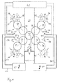
- FIGS Various advantageous drive configurations are shown in the following FIGS a nine-cylinder printing unit 01 shown.
- the two cylinders 03; 04 each printing unit 03 have each drive wheels 22; 23 (e.g. gears 22; 23) on and are via a pinion 24 from a common drive motor 12 Transfer cylinder 03 driven.
- the drive can also be coaxial, e.g. B. about a not shown, the above Additional gear.
- From the drive wheel of the Transfer cylinder 17 is then on the drive wheel 23 of the forme cylinder 03, and from there to the inking and / or dampening unit 07; 08 driven.
- the drive connection between the two cylinders 03; 04 can also be done with straps.
- the impression cylinder 02 is here driven by the two drive motors 09 via pinions 26 driven, which on a common drive wheel 27 or on two different, axially offset drive wheels 27 of the impression cylinder 02 drives. Between the drive motors 09; 12 and the drive wheels 22; 27 can do more Gear elements, such as. B. gears and / or belt drives can be provided.
- the Drive arrangement is of particular advantage with regard to a clear Torque flow in the printing unit 06 from the transfer cylinder 03 to the forme cylinder 04 and then e.g. on ink and, if necessary, dampening unit 07; 08.
- the energy supply is designed in such a way that the drive motors 12 of the left printing units 06 together with a Drive motor 09 of the impression cylinder 02 by a power supply 17 and the rest are supplied by the other power supply 17.
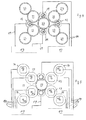
- the drive can again axially, for. B. about a not shown transmission, take place or on the drive wheel 23 of the Forme cylinder 04 driving pinion 24. From the drive wheel 23 of the forme cylinder 04 can then be driven on the drive wheel 22 of the transfer cylinder 03.
- the Drive connection and the drive of the ink and dampening unit 07; 08 how to Fig. 2 set out to be executed.
- the drive arrangement is of particular advantage in With regard to an actuating movement of the transfer cylinder 03, without a high effort in the storage of the drive motor 12 and / or compromises in Gear engagement would have to be considered.
- the energy supply is exemplary designed that the drive motors 12 of the upper printing units 06 together with a Drive motor 09 of the impression cylinder 02 by a power supply 17 and the rest are supplied by the other power supply 17.
- the supply scheme from FIG. 3 can be applied to the drive concept of FIG. 2 and vice versa.
- two pairs 03, 04 are each in a drive system driven together by a drive motor. It is from the two Transfer cylinders 03 driven "outside" (torque flow).
- the drive assembly can also be a variant of one of the two forme cylinders 04 be driven, with the transfer cylinder 03 between the drive wheels 22 at least one intermediate wheel is provided.
- the drive wheel 27 is or Drive wheels 27 are driven as described for FIG. 2. The concept sees that Supply of one drive motor 09 together with one of the drive motors 12 of the two drive systems.
- two distribution cylinders which rotate together by means of their own drive motor 14 can be driven via a gearbox indicated by dashed lines. They are to be created an axial stroke, for example, by a further drive means, not shown axially movable and drivable.
- the inking unit can also only have one distribution cylinder exhibit. The said is on the drive of the dampening unit 08 in the same way apply.
- the concept sees the supply of the drive motors 12 to two Printing units 06 together with a drive motor 09 of the impression cylinder 02.
- Fig. 6 shows a side view of the drive for the impression cylinder in the Version with a drive wheel connected torsionally rigid to the impression cylinder 02 27. This is driven by a drive motor 09, z. B. via an attachment gear 11, and a pinion 26 driven. In an embodiment not shown, the two pinions 26 drive on two axially offset drive wheels 27.
- FIG. 7 shows a satellite printing unit 01 with two satellite cylinders 02, to which two printing units 06 are assigned.
- printing units 06 with inking and possibly dampening unit 07; 08 applies the above and the same reference numerals.
- each of the two impression cylinders 02 has its own drive motor 09.
- the above-mentioned is to be used.
- a drive motor 09 which is arranged essentially coaxially with the cylinder 02 and which drives the cylinder 02 via a coaxial transmission (not shown) can be provided.
- the supply concepts of the drive motors 09; 12 and the drive concepts of the printing units 06 are to be used here.
- the drive motors 09 supplied according to FIGS. 2 to 5 do not drive on the same impression cylinder 02 but on two different impression cylinders 02.
- each Impression cylinder 02 two drive motors 09 are provided.
- the drive motors 12 are preferably referred to as their angular position controlled electric motors 12, z. B. as asynchronous motors, Synchronous motors or DC motors.
- the two too Drive motors 09 can be designed in this way. This is especially true if as in Fig. 7 is assigned to two counter-pressure cylinders 02, a drive motor 09.
- an impression cylinder 02 has two drive motors 09, it is from Advantage if one of the two drive motors 09 is regulated with respect to its angular position, and the other drive motor in terms of its moment (or its power).
- the Angular position-controlled drive motor 09 acts here, for. B. as a "master” during the other drive motor 09 as “slave” is torque-controlled.
- all drive motors 09; 12 the cylinder 02; 03; 04 the Printing unit 01 a common supply unit 17.
- the supply unit 17 is - like the two supply units 17 described above - designed to Drive power obtained from generator drive to at least one to lead a significant part back into the drive power for the motor drive.
- On called power supply 17 for supplying multiple drives in the manner described For example, an energy supply from a local network (print shop or Energy supplier), through which only energy is fed into the power supply, however is not recoverable from this.
- One (or more together) independent of other drives speed and / or position control drive motor 09; 11 shows that Power supply unit 17, for example a converter (in particular frequency converter), whose power requirements are fed from a common circuit. Electrical Energy, which is generated by a drive motor 09; 12 flows back, can in this way a motorized drive motor 12; 09 fed become. This energy is therefore not only converted into heat, but one made available to other consumers. A generator operated drive without Dispensing to a consumer would overheat if necessary.
- Power supply unit 17 for example a converter (in particular frequency converter)
- everyone in operation is regenerative operated drive motor 09; 12 (in particular 09) of the same printing unit at least one drive motor 12 operated in operation; 09 about that common power supply 17 assigned.
- a generator-driven drive motor 09; 12 thus flows energy, z. B. drive energy, in particular electrical energy, via the power supply 17 in the motorized Drive motor 12; 09th
Landscapes
- Engineering & Computer Science (AREA)
- Mechanical Engineering (AREA)
- Rotary Presses (AREA)
- Inking, Control Or Cleaning Of Printing Machines (AREA)
- Printers Or Recording Devices Using Electromagnetic And Radiation Means (AREA)
- Ink Jet (AREA)
- Printers Characterized By Their Purpose (AREA)
Applications Claiming Priority (2)
| Application Number | Priority Date | Filing Date | Title |
|---|---|---|---|
| DE10309092A DE10309092B3 (de) | 2003-03-03 | 2003-03-03 | Antrieb einer Druckeinheit |
| DE10309092 | 2003-03-03 |
Publications (3)
| Publication Number | Publication Date |
|---|---|
| EP1464488A2 true EP1464488A2 (fr) | 2004-10-06 |
| EP1464488A3 EP1464488A3 (fr) | 2008-10-29 |
| EP1464488B1 EP1464488B1 (fr) | 2010-04-28 |
Family
ID=32842095
Family Applications (1)
| Application Number | Title | Priority Date | Filing Date |
|---|---|---|---|
| EP04100557A Expired - Lifetime EP1464488B1 (fr) | 2003-03-03 | 2004-02-13 | Imprimante |
Country Status (3)
| Country | Link |
|---|---|
| EP (1) | EP1464488B1 (fr) |
| AT (1) | ATE465872T1 (fr) |
| DE (2) | DE10309092B3 (fr) |
Cited By (5)
| Publication number | Priority date | Publication date | Assignee | Title |
|---|---|---|---|---|
| DE102006056828A1 (de) * | 2006-12-01 | 2008-06-05 | Koenig & Bauer Aktiengesellschaft | Satellitendruckeinheit und einen Druckturm |
| DE102007008539A1 (de) * | 2007-02-21 | 2008-09-04 | Koenig & Bauer Aktiengesellschaft | Satellitendruckeinheit und einen Druckturm |
| FR2927837A1 (fr) * | 2008-02-25 | 2009-08-28 | Goss Int Montataire Sa | Unite d'impression pour presse rotative. |
| DE102008040132A1 (de) | 2008-07-03 | 2010-01-14 | Koenig & Bauer Aktiengesellschaft | Maschineneinheit einer Druckmaschine mit mindestens einer Antriebseinheit |
| EP2159050A3 (fr) * | 2008-09-02 | 2011-12-21 | Fischer & Krecke GmbH | Procédé de fonctionnement d'une machine d'impression à cylindre central |
Families Citing this family (3)
| Publication number | Priority date | Publication date | Assignee | Title |
|---|---|---|---|---|
| US7383771B2 (en) * | 2003-12-05 | 2008-06-10 | Man Roland Druckmaschinen Ag | Web-fed rotary printing unit |
| DE102006003005B3 (de) * | 2005-06-17 | 2006-11-23 | Koenig & Bauer Ag | Flexodruckmaschine |
| DE102009001304A1 (de) * | 2009-03-03 | 2010-09-09 | Manroland Ag | Druckeinheit einer Rollenrotationsdruckmaschine |
Citations (7)
| Publication number | Priority date | Publication date | Assignee | Title |
|---|---|---|---|---|
| DE4344896A1 (de) | 1993-12-29 | 1995-07-06 | Wifag Maschf | Rotationsdruckmaschine mit paarweise zu Zylindergruppen zusammengefaßten Gummituch- und Platten- bzw. Formzylindern |
| EP0669208A1 (fr) | 1994-02-28 | 1995-08-30 | Ward Holding Company, Inc. | Montage d'arbre et dispositif pour une machine de traitement de flancs de carton |
| DE19525593C2 (de) | 1995-07-13 | 1997-04-30 | Roland Man Druckmasch | Mehrmotorenantrieb für eine Druckmaschine |
| DE19723059A1 (de) | 1997-06-02 | 1998-12-03 | Wifag Maschf | Registerhaltige Abstimmung von Druckzylindern einer Rollenrotationsmaschine |
| DE19732330A1 (de) | 1997-07-28 | 1999-02-04 | Koenig & Bauer Albert Ag | Druckeinheit |
| WO2002024452A2 (fr) | 2000-09-20 | 2002-03-28 | Koenig & Bauer Aktiengesellschaft | Unite d'impression |
| WO2002074540A1 (fr) | 2001-03-20 | 2002-09-26 | Koenig & Bauer Aktiengesellschaft | Procedes et dispositifs pour entrainer une unite d'impression |
Family Cites Families (2)
| Publication number | Priority date | Publication date | Assignee | Title |
|---|---|---|---|---|
| DE10016409B4 (de) * | 1999-12-02 | 2007-03-15 | Koenig & Bauer Ag | Druckeinheit einer Rotationsdruckmaschine |
| WO2003016057A1 (fr) * | 2001-08-03 | 2003-02-27 | Koenig & Bauer Aktiengesellschaft | Elements d'impression pour presse d'imprimerie |
-
2003
- 2003-03-03 DE DE10309092A patent/DE10309092B3/de not_active Expired - Fee Related
-
2004
- 2004-02-13 AT AT04100557T patent/ATE465872T1/de active
- 2004-02-13 EP EP04100557A patent/EP1464488B1/fr not_active Expired - Lifetime
- 2004-02-13 DE DE502004011088T patent/DE502004011088D1/de not_active Expired - Lifetime
Patent Citations (7)
| Publication number | Priority date | Publication date | Assignee | Title |
|---|---|---|---|---|
| DE4344896A1 (de) | 1993-12-29 | 1995-07-06 | Wifag Maschf | Rotationsdruckmaschine mit paarweise zu Zylindergruppen zusammengefaßten Gummituch- und Platten- bzw. Formzylindern |
| EP0669208A1 (fr) | 1994-02-28 | 1995-08-30 | Ward Holding Company, Inc. | Montage d'arbre et dispositif pour une machine de traitement de flancs de carton |
| DE19525593C2 (de) | 1995-07-13 | 1997-04-30 | Roland Man Druckmasch | Mehrmotorenantrieb für eine Druckmaschine |
| DE19723059A1 (de) | 1997-06-02 | 1998-12-03 | Wifag Maschf | Registerhaltige Abstimmung von Druckzylindern einer Rollenrotationsmaschine |
| DE19732330A1 (de) | 1997-07-28 | 1999-02-04 | Koenig & Bauer Albert Ag | Druckeinheit |
| WO2002024452A2 (fr) | 2000-09-20 | 2002-03-28 | Koenig & Bauer Aktiengesellschaft | Unite d'impression |
| WO2002074540A1 (fr) | 2001-03-20 | 2002-09-26 | Koenig & Bauer Aktiengesellschaft | Procedes et dispositifs pour entrainer une unite d'impression |
Cited By (8)
| Publication number | Priority date | Publication date | Assignee | Title |
|---|---|---|---|---|
| DE102006056828A1 (de) * | 2006-12-01 | 2008-06-05 | Koenig & Bauer Aktiengesellschaft | Satellitendruckeinheit und einen Druckturm |
| DE102006056828B4 (de) * | 2006-12-01 | 2010-04-08 | Koenig & Bauer Aktiengesellschaft | Satellitendruckeinheit und ein Druckturm |
| DE102007008539A1 (de) * | 2007-02-21 | 2008-09-04 | Koenig & Bauer Aktiengesellschaft | Satellitendruckeinheit und einen Druckturm |
| DE102007008539B4 (de) * | 2007-02-21 | 2009-11-12 | Koenig & Bauer Aktiengesellschaft | Satellitendruckeinheit und ein Druckturm |
| FR2927837A1 (fr) * | 2008-02-25 | 2009-08-28 | Goss Int Montataire Sa | Unite d'impression pour presse rotative. |
| DE102008040132A1 (de) | 2008-07-03 | 2010-01-14 | Koenig & Bauer Aktiengesellschaft | Maschineneinheit einer Druckmaschine mit mindestens einer Antriebseinheit |
| DE102008040132B4 (de) * | 2008-07-03 | 2011-07-21 | KOENIG & BAUER Aktiengesellschaft, 97080 | Maschineneinheit einer Druckmaschine mit mindestens einer Antriebseinheit |
| EP2159050A3 (fr) * | 2008-09-02 | 2011-12-21 | Fischer & Krecke GmbH | Procédé de fonctionnement d'une machine d'impression à cylindre central |
Also Published As
| Publication number | Publication date |
|---|---|
| EP1464488B1 (fr) | 2010-04-28 |
| DE10309092B3 (de) | 2004-09-09 |
| DE502004011088D1 (de) | 2010-06-10 |
| ATE465872T1 (de) | 2010-05-15 |
| EP1464488A3 (fr) | 2008-10-29 |
Similar Documents
| Publication | Publication Date | Title |
|---|---|---|
| EP0699524B2 (fr) | Machine rotative d'impression offset à bobines | |
| EP0919372B1 (fr) | Groupe imprimant pour une rotative | |
| EP0753405B1 (fr) | Dispositif d'entraínement à plusiers moteurs pour une machine à imprimer | |
| DE19942619A1 (de) | Druckwerk in einer Rollenrotations-Offsetdruckmaschine zur Durchführung eines fliegenden Plattenwechsels | |
| EP2195166A1 (fr) | Dispositif d'encrage d'une presse à imprimer | |
| DE10121245A1 (de) | Druckwerksanordnung in einer Rollenrotationsdruckmaschine | |
| EP1412183A1 (fr) | Elements d'impression pour presse d'imprimerie | |
| DE10309092B3 (de) | Antrieb einer Druckeinheit | |
| EP1318909A1 (fr) | Unite d'impression | |
| EP1226937B1 (fr) | Entraînement sans arbre à moteur pour une machine d'impression avec un rouleau d'encrage anilox | |
| EP1412184A1 (fr) | Elements d'impression pour presse d'imprimerie | |
| DE10327490B4 (de) | Druckeinheit einer Rotationsdruckmaschine | |
| DE10304296B4 (de) | Antrieb eines Druckwerkes | |
| DE10350098A1 (de) | Antrieb für eine Offsetdruckmaschine | |
| DE102005014060B4 (de) | Farbwerk einer Druckmaschine | |
| EP3370965B1 (fr) | Entraînement pour presses à feuilles rotatives | |
| DE102007039235A1 (de) | Verfahren und Vorrichtung zum Antreiben einer Rotationsbogendruckmaschine mit mehreren Druckwerken | |
| DE10046365B4 (de) | Verfahren und Vorrichtung zum Antrieb einer Druckeinheit | |
| DE10229784A1 (de) | Druckwerke einer Druckmaschine | |
| WO2003016058A1 (fr) | Elements d'impression pour presse d'imprimerie | |
| EP1492673A1 (fr) | Unites d impression | |
| CH698434B1 (de) | Rollenrotationsdruckeinheit. | |
| DE10315196A1 (de) | Druckeinheiten | |
| WO2002070259A1 (fr) | Unite d'impression | |
| DE102013226314A1 (de) | Verfahren zum Betreiben einer Druckmaschine und Druckmaschine |
Legal Events
| Date | Code | Title | Description |
|---|---|---|---|
| PUAI | Public reference made under article 153(3) epc to a published international application that has entered the european phase |
Free format text: ORIGINAL CODE: 0009012 |
|
| AK | Designated contracting states |
Kind code of ref document: A2 Designated state(s): AT BE BG CH CY CZ DE DK EE ES FI FR GB GR HU IE IT LI LU MC NL PT RO SE SI SK TR |
|
| AX | Request for extension of the european patent |
Extension state: AL LT LV MK |
|
| PUAL | Search report despatched |
Free format text: ORIGINAL CODE: 0009013 |
|
| AK | Designated contracting states |
Kind code of ref document: A3 Designated state(s): AT BE BG CH CY CZ DE DK EE ES FI FR GB GR HU IE IT LI LU MC NL PT RO SE SI SK TR |
|
| AX | Request for extension of the european patent |
Extension state: AL LT LV MK |
|
| 17P | Request for examination filed |
Effective date: 20081006 |
|
| 17Q | First examination report despatched |
Effective date: 20090310 |
|
| AKX | Designation fees paid |
Designated state(s): AT BE BG CH CY CZ DE DK EE ES FI FR GB GR HU IE IT LI LU MC NL PT RO SE SI SK TR |
|
| RTI1 | Title (correction) |
Free format text: PRINTING UNIT |
|
| GRAP | Despatch of communication of intention to grant a patent |
Free format text: ORIGINAL CODE: EPIDOSNIGR1 |
|
| GRAS | Grant fee paid |
Free format text: ORIGINAL CODE: EPIDOSNIGR3 |
|
| GRAA | (expected) grant |
Free format text: ORIGINAL CODE: 0009210 |
|
| AK | Designated contracting states |
Kind code of ref document: B1 Designated state(s): AT BE BG CH CY CZ DE DK EE ES FI FR GB GR HU IE IT LI LU MC NL PT RO SE SI SK TR |
|
| REG | Reference to a national code |
Ref country code: GB Ref legal event code: FG4D Free format text: NOT ENGLISH |
|
| REG | Reference to a national code |
Ref country code: CH Ref legal event code: EP |
|
| REG | Reference to a national code |
Ref country code: IE Ref legal event code: FG4D Free format text: LANGUAGE OF EP DOCUMENT: GERMAN |
|
| REF | Corresponds to: |
Ref document number: 502004011088 Country of ref document: DE Date of ref document: 20100610 Kind code of ref document: P |
|
| REG | Reference to a national code |
Ref country code: NL Ref legal event code: VDEP Effective date: 20100428 |
|
| PG25 | Lapsed in a contracting state [announced via postgrant information from national office to epo] |
Ref country code: ES Free format text: LAPSE BECAUSE OF FAILURE TO SUBMIT A TRANSLATION OF THE DESCRIPTION OR TO PAY THE FEE WITHIN THE PRESCRIBED TIME-LIMIT Effective date: 20100808 Ref country code: NL Free format text: LAPSE BECAUSE OF FAILURE TO SUBMIT A TRANSLATION OF THE DESCRIPTION OR TO PAY THE FEE WITHIN THE PRESCRIBED TIME-LIMIT Effective date: 20100428 Ref country code: SE Free format text: LAPSE BECAUSE OF FAILURE TO SUBMIT A TRANSLATION OF THE DESCRIPTION OR TO PAY THE FEE WITHIN THE PRESCRIBED TIME-LIMIT Effective date: 20100428 |
|
| REG | Reference to a national code |
Ref country code: IE Ref legal event code: FD4D |
|
| PG25 | Lapsed in a contracting state [announced via postgrant information from national office to epo] |
Ref country code: SI Free format text: LAPSE BECAUSE OF FAILURE TO SUBMIT A TRANSLATION OF THE DESCRIPTION OR TO PAY THE FEE WITHIN THE PRESCRIBED TIME-LIMIT Effective date: 20100428 Ref country code: FI Free format text: LAPSE BECAUSE OF FAILURE TO SUBMIT A TRANSLATION OF THE DESCRIPTION OR TO PAY THE FEE WITHIN THE PRESCRIBED TIME-LIMIT Effective date: 20100428 |
|
| PG25 | Lapsed in a contracting state [announced via postgrant information from national office to epo] |
Ref country code: CY Free format text: LAPSE BECAUSE OF FAILURE TO SUBMIT A TRANSLATION OF THE DESCRIPTION OR TO PAY THE FEE WITHIN THE PRESCRIBED TIME-LIMIT Effective date: 20100428 Ref country code: GR Free format text: LAPSE BECAUSE OF FAILURE TO SUBMIT A TRANSLATION OF THE DESCRIPTION OR TO PAY THE FEE WITHIN THE PRESCRIBED TIME-LIMIT Effective date: 20100729 |
|
| PG25 | Lapsed in a contracting state [announced via postgrant information from national office to epo] |
Ref country code: IE Free format text: LAPSE BECAUSE OF FAILURE TO SUBMIT A TRANSLATION OF THE DESCRIPTION OR TO PAY THE FEE WITHIN THE PRESCRIBED TIME-LIMIT Effective date: 20100428 Ref country code: PT Free format text: LAPSE BECAUSE OF FAILURE TO SUBMIT A TRANSLATION OF THE DESCRIPTION OR TO PAY THE FEE WITHIN THE PRESCRIBED TIME-LIMIT Effective date: 20100830 Ref country code: EE Free format text: LAPSE BECAUSE OF FAILURE TO SUBMIT A TRANSLATION OF THE DESCRIPTION OR TO PAY THE FEE WITHIN THE PRESCRIBED TIME-LIMIT Effective date: 20100428 Ref country code: DK Free format text: LAPSE BECAUSE OF FAILURE TO SUBMIT A TRANSLATION OF THE DESCRIPTION OR TO PAY THE FEE WITHIN THE PRESCRIBED TIME-LIMIT Effective date: 20100428 |
|
| PG25 | Lapsed in a contracting state [announced via postgrant information from national office to epo] |
Ref country code: SK Free format text: LAPSE BECAUSE OF FAILURE TO SUBMIT A TRANSLATION OF THE DESCRIPTION OR TO PAY THE FEE WITHIN THE PRESCRIBED TIME-LIMIT Effective date: 20100428 Ref country code: RO Free format text: LAPSE BECAUSE OF FAILURE TO SUBMIT A TRANSLATION OF THE DESCRIPTION OR TO PAY THE FEE WITHIN THE PRESCRIBED TIME-LIMIT Effective date: 20100428 Ref country code: CZ Free format text: LAPSE BECAUSE OF FAILURE TO SUBMIT A TRANSLATION OF THE DESCRIPTION OR TO PAY THE FEE WITHIN THE PRESCRIBED TIME-LIMIT Effective date: 20100428 |
|
| PLBE | No opposition filed within time limit |
Free format text: ORIGINAL CODE: 0009261 |
|
| STAA | Information on the status of an ep patent application or granted ep patent |
Free format text: STATUS: NO OPPOSITION FILED WITHIN TIME LIMIT |
|
| PG25 | Lapsed in a contracting state [announced via postgrant information from national office to epo] |
Ref country code: IT Free format text: LAPSE BECAUSE OF FAILURE TO SUBMIT A TRANSLATION OF THE DESCRIPTION OR TO PAY THE FEE WITHIN THE PRESCRIBED TIME-LIMIT Effective date: 20100428 |
|
| 26N | No opposition filed |
Effective date: 20110131 |
|
| BERE | Be: lapsed |
Owner name: KOENIG & BAUER A.G. Effective date: 20110228 |
|
| PG25 | Lapsed in a contracting state [announced via postgrant information from national office to epo] |
Ref country code: MC Free format text: LAPSE BECAUSE OF NON-PAYMENT OF DUE FEES Effective date: 20110228 |
|
| PG25 | Lapsed in a contracting state [announced via postgrant information from national office to epo] |
Ref country code: BE Free format text: LAPSE BECAUSE OF NON-PAYMENT OF DUE FEES Effective date: 20110228 |
|
| PGFP | Annual fee paid to national office [announced via postgrant information from national office to epo] |
Ref country code: FR Payment date: 20120229 Year of fee payment: 9 Ref country code: CH Payment date: 20120227 Year of fee payment: 9 |
|
| PGFP | Annual fee paid to national office [announced via postgrant information from national office to epo] |
Ref country code: DE Payment date: 20120315 Year of fee payment: 9 |
|
| PGFP | Annual fee paid to national office [announced via postgrant information from national office to epo] |
Ref country code: GB Payment date: 20120221 Year of fee payment: 9 |
|
| REG | Reference to a national code |
Ref country code: AT Ref legal event code: MM01 Ref document number: 465872 Country of ref document: AT Kind code of ref document: T Effective date: 20110213 |
|
| PG25 | Lapsed in a contracting state [announced via postgrant information from national office to epo] |
Ref country code: AT Free format text: LAPSE BECAUSE OF NON-PAYMENT OF DUE FEES Effective date: 20110213 |
|
| PG25 | Lapsed in a contracting state [announced via postgrant information from national office to epo] |
Ref country code: LU Free format text: LAPSE BECAUSE OF NON-PAYMENT OF DUE FEES Effective date: 20110213 |
|
| PG25 | Lapsed in a contracting state [announced via postgrant information from national office to epo] |
Ref country code: TR Free format text: LAPSE BECAUSE OF FAILURE TO SUBMIT A TRANSLATION OF THE DESCRIPTION OR TO PAY THE FEE WITHIN THE PRESCRIBED TIME-LIMIT Effective date: 20100428 Ref country code: BG Free format text: LAPSE BECAUSE OF FAILURE TO SUBMIT A TRANSLATION OF THE DESCRIPTION OR TO PAY THE FEE WITHIN THE PRESCRIBED TIME-LIMIT Effective date: 20100728 |
|
| REG | Reference to a national code |
Ref country code: CH Ref legal event code: PL |
|
| GBPC | Gb: european patent ceased through non-payment of renewal fee |
Effective date: 20130213 |
|
| PG25 | Lapsed in a contracting state [announced via postgrant information from national office to epo] |
Ref country code: CH Free format text: LAPSE BECAUSE OF NON-PAYMENT OF DUE FEES Effective date: 20130228 Ref country code: HU Free format text: LAPSE BECAUSE OF FAILURE TO SUBMIT A TRANSLATION OF THE DESCRIPTION OR TO PAY THE FEE WITHIN THE PRESCRIBED TIME-LIMIT Effective date: 20100428 Ref country code: LI Free format text: LAPSE BECAUSE OF NON-PAYMENT OF DUE FEES Effective date: 20130228 |
|
| REG | Reference to a national code |
Ref country code: FR Ref legal event code: ST Effective date: 20131031 |
|
| REG | Reference to a national code |
Ref country code: DE Ref legal event code: R119 Ref document number: 502004011088 Country of ref document: DE Effective date: 20130903 |
|
| PG25 | Lapsed in a contracting state [announced via postgrant information from national office to epo] |
Ref country code: DE Free format text: LAPSE BECAUSE OF NON-PAYMENT OF DUE FEES Effective date: 20130903 Ref country code: GB Free format text: LAPSE BECAUSE OF NON-PAYMENT OF DUE FEES Effective date: 20130213 Ref country code: FR Free format text: LAPSE BECAUSE OF NON-PAYMENT OF DUE FEES Effective date: 20130228 |