EP1464816A2 - Diagnosesystem für eine Abgasnachbehandlungsanlage einer Brennkraftmaschine - Google Patents
Diagnosesystem für eine Abgasnachbehandlungsanlage einer Brennkraftmaschine Download PDFInfo
- Publication number
- EP1464816A2 EP1464816A2 EP04008006A EP04008006A EP1464816A2 EP 1464816 A2 EP1464816 A2 EP 1464816A2 EP 04008006 A EP04008006 A EP 04008006A EP 04008006 A EP04008006 A EP 04008006A EP 1464816 A2 EP1464816 A2 EP 1464816A2
- Authority
- EP
- European Patent Office
- Prior art keywords
- exhaust
- deterioration
- aftertreatment apparatus
- exhaust aftertreatment
- fuel ratio
- Prior art date
- Legal status (The legal status is an assumption and is not a legal conclusion. Google has not performed a legal analysis and makes no representation as to the accuracy of the status listed.)
- Granted
Links
Images







Classifications
-
- F—MECHANICAL ENGINEERING; LIGHTING; HEATING; WEAPONS; BLASTING
- F01—MACHINES OR ENGINES IN GENERAL; ENGINE PLANTS IN GENERAL; STEAM ENGINES
- F01N—GAS-FLOW SILENCERS OR EXHAUST APPARATUS FOR MACHINES OR ENGINES IN GENERAL; GAS-FLOW SILENCERS OR EXHAUST APPARATUS FOR INTERNAL-COMBUSTION ENGINES
- F01N3/00—Exhaust or silencing apparatus having means for purifying, rendering innocuous, or otherwise treating exhaust
- F01N3/08—Exhaust or silencing apparatus having means for purifying, rendering innocuous, or otherwise treating exhaust for rendering innocuous
- F01N3/0807—Exhaust or silencing apparatus having means for purifying, rendering innocuous, or otherwise treating exhaust for rendering innocuous by using absorbents or adsorbents
- F01N3/0828—Exhaust or silencing apparatus having means for purifying, rendering innocuous, or otherwise treating exhaust for rendering innocuous by using absorbents or adsorbents characterised by the absorbed or adsorbed substances
- F01N3/0842—Nitrogen oxides
-
- F—MECHANICAL ENGINEERING; LIGHTING; HEATING; WEAPONS; BLASTING
- F01—MACHINES OR ENGINES IN GENERAL; ENGINE PLANTS IN GENERAL; STEAM ENGINES
- F01N—GAS-FLOW SILENCERS OR EXHAUST APPARATUS FOR MACHINES OR ENGINES IN GENERAL; GAS-FLOW SILENCERS OR EXHAUST APPARATUS FOR INTERNAL-COMBUSTION ENGINES
- F01N11/00—Monitoring or diagnostic devices for exhaust-gas treatment apparatus
-
- F—MECHANICAL ENGINEERING; LIGHTING; HEATING; WEAPONS; BLASTING
- F01—MACHINES OR ENGINES IN GENERAL; ENGINE PLANTS IN GENERAL; STEAM ENGINES
- F01N—GAS-FLOW SILENCERS OR EXHAUST APPARATUS FOR MACHINES OR ENGINES IN GENERAL; GAS-FLOW SILENCERS OR EXHAUST APPARATUS FOR INTERNAL-COMBUSTION ENGINES
- F01N11/00—Monitoring or diagnostic devices for exhaust-gas treatment apparatus
- F01N11/002—Monitoring or diagnostic devices for exhaust-gas treatment apparatus the diagnostic devices measuring or estimating temperature or pressure in, or downstream of the exhaust apparatus
-
- F—MECHANICAL ENGINEERING; LIGHTING; HEATING; WEAPONS; BLASTING
- F01—MACHINES OR ENGINES IN GENERAL; ENGINE PLANTS IN GENERAL; STEAM ENGINES
- F01N—GAS-FLOW SILENCERS OR EXHAUST APPARATUS FOR MACHINES OR ENGINES IN GENERAL; GAS-FLOW SILENCERS OR EXHAUST APPARATUS FOR INTERNAL-COMBUSTION ENGINES
- F01N11/00—Monitoring or diagnostic devices for exhaust-gas treatment apparatus
- F01N11/007—Monitoring or diagnostic devices for exhaust-gas treatment apparatus the diagnostic devices measuring oxygen or air concentration downstream of the exhaust apparatus
-
- F—MECHANICAL ENGINEERING; LIGHTING; HEATING; WEAPONS; BLASTING
- F01—MACHINES OR ENGINES IN GENERAL; ENGINE PLANTS IN GENERAL; STEAM ENGINES
- F01N—GAS-FLOW SILENCERS OR EXHAUST APPARATUS FOR MACHINES OR ENGINES IN GENERAL; GAS-FLOW SILENCERS OR EXHAUST APPARATUS FOR INTERNAL-COMBUSTION ENGINES
- F01N13/00—Exhaust or silencing apparatus characterised by constructional features
- F01N13/009—Exhaust or silencing apparatus characterised by constructional features having two or more separate purifying devices arranged in series
-
- F—MECHANICAL ENGINEERING; LIGHTING; HEATING; WEAPONS; BLASTING
- F01—MACHINES OR ENGINES IN GENERAL; ENGINE PLANTS IN GENERAL; STEAM ENGINES
- F01N—GAS-FLOW SILENCERS OR EXHAUST APPARATUS FOR MACHINES OR ENGINES IN GENERAL; GAS-FLOW SILENCERS OR EXHAUST APPARATUS FOR INTERNAL-COMBUSTION ENGINES
- F01N3/00—Exhaust or silencing apparatus having means for purifying, rendering innocuous, or otherwise treating exhaust
- F01N3/08—Exhaust or silencing apparatus having means for purifying, rendering innocuous, or otherwise treating exhaust for rendering innocuous
- F01N3/0807—Exhaust or silencing apparatus having means for purifying, rendering innocuous, or otherwise treating exhaust for rendering innocuous by using absorbents or adsorbents
- F01N3/0814—Exhaust or silencing apparatus having means for purifying, rendering innocuous, or otherwise treating exhaust for rendering innocuous by using absorbents or adsorbents combined with catalytic converters, e.g. NOx absorption/storage reduction catalysts
-
- F—MECHANICAL ENGINEERING; LIGHTING; HEATING; WEAPONS; BLASTING
- F02—COMBUSTION ENGINES; HOT-GAS OR COMBUSTION-PRODUCT ENGINE PLANTS
- F02D—CONTROLLING COMBUSTION ENGINES
- F02D41/00—Electrical control of supply of combustible mixture or its constituents
- F02D41/02—Circuit arrangements for generating control signals
- F02D41/021—Introducing corrections for particular conditions exterior to the engine
- F02D41/0235—Introducing corrections for particular conditions exterior to the engine in relation with the state of the exhaust gas treating apparatus
- F02D41/027—Introducing corrections for particular conditions exterior to the engine in relation with the state of the exhaust gas treating apparatus to purge or regenerate the exhaust gas treating apparatus
- F02D41/0275—Introducing corrections for particular conditions exterior to the engine in relation with the state of the exhaust gas treating apparatus to purge or regenerate the exhaust gas treating apparatus the exhaust gas treating apparatus being a NOx trap or adsorbent
-
- F—MECHANICAL ENGINEERING; LIGHTING; HEATING; WEAPONS; BLASTING
- F02—COMBUSTION ENGINES; HOT-GAS OR COMBUSTION-PRODUCT ENGINE PLANTS
- F02D—CONTROLLING COMBUSTION ENGINES
- F02D41/00—Electrical control of supply of combustible mixture or its constituents
- F02D41/02—Circuit arrangements for generating control signals
- F02D41/14—Introducing closed-loop corrections
- F02D41/1438—Introducing closed-loop corrections using means for determining characteristics of the combustion gases; Sensors therefor
- F02D41/1439—Introducing closed-loop corrections using means for determining characteristics of the combustion gases; Sensors therefor characterised by the position of the sensor
- F02D41/1441—Plural sensors
-
- F—MECHANICAL ENGINEERING; LIGHTING; HEATING; WEAPONS; BLASTING
- F02—COMBUSTION ENGINES; HOT-GAS OR COMBUSTION-PRODUCT ENGINE PLANTS
- F02D—CONTROLLING COMBUSTION ENGINES
- F02D41/00—Electrical control of supply of combustible mixture or its constituents
- F02D41/02—Circuit arrangements for generating control signals
- F02D41/14—Introducing closed-loop corrections
- F02D41/1438—Introducing closed-loop corrections using means for determining characteristics of the combustion gases; Sensors therefor
- F02D41/1493—Details
- F02D41/1495—Detection of abnormalities in the air/fuel ratio feedback system
-
- F—MECHANICAL ENGINEERING; LIGHTING; HEATING; WEAPONS; BLASTING
- F02—COMBUSTION ENGINES; HOT-GAS OR COMBUSTION-PRODUCT ENGINE PLANTS
- F02D—CONTROLLING COMBUSTION ENGINES
- F02D41/00—Electrical control of supply of combustible mixture or its constituents
- F02D41/22—Safety or indicating devices for abnormal conditions
- F02D41/221—Safety or indicating devices for abnormal conditions relating to the failure of actuators or electrically driven elements
-
- F—MECHANICAL ENGINEERING; LIGHTING; HEATING; WEAPONS; BLASTING
- F02—COMBUSTION ENGINES; HOT-GAS OR COMBUSTION-PRODUCT ENGINE PLANTS
- F02B—INTERNAL-COMBUSTION PISTON ENGINES; COMBUSTION ENGINES IN GENERAL
- F02B2275/00—Other engines, components or details, not provided for in other groups of this subclass
- F02B2275/14—Direct injection into combustion chamber
-
- F—MECHANICAL ENGINEERING; LIGHTING; HEATING; WEAPONS; BLASTING
- F02—COMBUSTION ENGINES; HOT-GAS OR COMBUSTION-PRODUCT ENGINE PLANTS
- F02B—INTERNAL-COMBUSTION PISTON ENGINES; COMBUSTION ENGINES IN GENERAL
- F02B29/00—Engines characterised by provision for charging or scavenging not provided for in groups F02B25/00, F02B27/00 or F02B33/00 - F02B39/00; Details thereof
- F02B29/04—Cooling of air intake supply
- F02B29/0406—Layout of the intake air cooling or coolant circuit
-
- F—MECHANICAL ENGINEERING; LIGHTING; HEATING; WEAPONS; BLASTING
- F02—COMBUSTION ENGINES; HOT-GAS OR COMBUSTION-PRODUCT ENGINE PLANTS
- F02B—INTERNAL-COMBUSTION PISTON ENGINES; COMBUSTION ENGINES IN GENERAL
- F02B3/00—Engines characterised by air compression and subsequent fuel addition
- F02B3/06—Engines characterised by air compression and subsequent fuel addition with compression ignition
-
- F—MECHANICAL ENGINEERING; LIGHTING; HEATING; WEAPONS; BLASTING
- F02—COMBUSTION ENGINES; HOT-GAS OR COMBUSTION-PRODUCT ENGINE PLANTS
- F02B—INTERNAL-COMBUSTION PISTON ENGINES; COMBUSTION ENGINES IN GENERAL
- F02B37/00—Engines characterised by provision of pumps driven at least for part of the time by exhaust
-
- F—MECHANICAL ENGINEERING; LIGHTING; HEATING; WEAPONS; BLASTING
- F02—COMBUSTION ENGINES; HOT-GAS OR COMBUSTION-PRODUCT ENGINE PLANTS
- F02D—CONTROLLING COMBUSTION ENGINES
- F02D41/00—Electrical control of supply of combustible mixture or its constituents
- F02D41/02—Circuit arrangements for generating control signals
- F02D41/14—Introducing closed-loop corrections
- F02D41/1438—Introducing closed-loop corrections using means for determining characteristics of the combustion gases; Sensors therefor
- F02D41/1473—Introducing closed-loop corrections using means for determining characteristics of the combustion gases; Sensors therefor characterised by the regulation method
- F02D41/1475—Regulating the air fuel ratio at a value other than stoichiometry
-
- F—MECHANICAL ENGINEERING; LIGHTING; HEATING; WEAPONS; BLASTING
- F02—COMBUSTION ENGINES; HOT-GAS OR COMBUSTION-PRODUCT ENGINE PLANTS
- F02M—SUPPLYING COMBUSTION ENGINES IN GENERAL WITH COMBUSTIBLE MIXTURES OR CONSTITUENTS THEREOF
- F02M26/00—Engine-pertinent apparatus for adding exhaust gases to combustion-air, main fuel or fuel-air mixture, e.g. by exhaust gas recirculation [EGR] systems
- F02M26/02—EGR systems specially adapted for supercharged engines
- F02M26/04—EGR systems specially adapted for supercharged engines with a single turbocharger
- F02M26/05—High pressure loops, i.e. wherein recirculated exhaust gas is taken out from the exhaust system upstream of the turbine and reintroduced into the intake system downstream of the compressor
-
- F—MECHANICAL ENGINEERING; LIGHTING; HEATING; WEAPONS; BLASTING
- F02—COMBUSTION ENGINES; HOT-GAS OR COMBUSTION-PRODUCT ENGINE PLANTS
- F02M—SUPPLYING COMBUSTION ENGINES IN GENERAL WITH COMBUSTIBLE MIXTURES OR CONSTITUENTS THEREOF
- F02M26/00—Engine-pertinent apparatus for adding exhaust gases to combustion-air, main fuel or fuel-air mixture, e.g. by exhaust gas recirculation [EGR] systems
- F02M26/02—EGR systems specially adapted for supercharged engines
- F02M26/09—Constructional details, e.g. structural combinations of EGR systems and supercharger systems; Arrangement of the EGR and supercharger systems with respect to the engine
- F02M26/10—Constructional details, e.g. structural combinations of EGR systems and supercharger systems; Arrangement of the EGR and supercharger systems with respect to the engine having means to increase the pressure difference between the exhaust and intake system, e.g. venturis, variable geometry turbines, check valves using pressure pulsations or throttles in the air intake or exhaust system
-
- F—MECHANICAL ENGINEERING; LIGHTING; HEATING; WEAPONS; BLASTING
- F02—COMBUSTION ENGINES; HOT-GAS OR COMBUSTION-PRODUCT ENGINE PLANTS
- F02M—SUPPLYING COMBUSTION ENGINES IN GENERAL WITH COMBUSTIBLE MIXTURES OR CONSTITUENTS THEREOF
- F02M26/00—Engine-pertinent apparatus for adding exhaust gases to combustion-air, main fuel or fuel-air mixture, e.g. by exhaust gas recirculation [EGR] systems
- F02M26/13—Arrangement or layout of EGR passages, e.g. in relation to specific engine parts or for incorporation of accessories
- F02M26/14—Arrangement or layout of EGR passages, e.g. in relation to specific engine parts or for incorporation of accessories in relation to the exhaust system
- F02M26/15—Arrangement or layout of EGR passages, e.g. in relation to specific engine parts or for incorporation of accessories in relation to the exhaust system in relation to engine exhaust purifying apparatus
-
- F—MECHANICAL ENGINEERING; LIGHTING; HEATING; WEAPONS; BLASTING
- F02—COMBUSTION ENGINES; HOT-GAS OR COMBUSTION-PRODUCT ENGINE PLANTS
- F02M—SUPPLYING COMBUSTION ENGINES IN GENERAL WITH COMBUSTIBLE MIXTURES OR CONSTITUENTS THEREOF
- F02M26/00—Engine-pertinent apparatus for adding exhaust gases to combustion-air, main fuel or fuel-air mixture, e.g. by exhaust gas recirculation [EGR] systems
- F02M26/45—Sensors specially adapted for EGR systems
- F02M26/46—Sensors specially adapted for EGR systems for determining the characteristics of gases, e.g. composition
-
- F—MECHANICAL ENGINEERING; LIGHTING; HEATING; WEAPONS; BLASTING
- F02—COMBUSTION ENGINES; HOT-GAS OR COMBUSTION-PRODUCT ENGINE PLANTS
- F02M—SUPPLYING COMBUSTION ENGINES IN GENERAL WITH COMBUSTIBLE MIXTURES OR CONSTITUENTS THEREOF
- F02M63/00—Other fuel-injection apparatus having pertinent characteristics not provided for in groups F02M39/00 - F02M57/00 or F02M67/00; Details, component parts, or accessories of fuel-injection apparatus, not provided for in, or of interest apart from, the apparatus of groups F02M39/00 - F02M61/00 or F02M67/00; Combination of fuel pump with other devices, e.g. lubricating oil pump
- F02M63/02—Fuel-injection apparatus having several injectors fed by a common pumping element, or having several pumping elements feeding a common injector; Fuel-injection apparatus having provisions for cutting-out pumps, pumping elements, or injectors; Fuel-injection apparatus having provisions for variably interconnecting pumping elements and injectors alternatively
- F02M63/0225—Fuel-injection apparatus having a common rail feeding several injectors ; Means for varying pressure in common rails; Pumps feeding common rails
-
- Y—GENERAL TAGGING OF NEW TECHNOLOGICAL DEVELOPMENTS; GENERAL TAGGING OF CROSS-SECTIONAL TECHNOLOGIES SPANNING OVER SEVERAL SECTIONS OF THE IPC; TECHNICAL SUBJECTS COVERED BY FORMER USPC CROSS-REFERENCE ART COLLECTIONS [XRACs] AND DIGESTS
- Y02—TECHNOLOGIES OR APPLICATIONS FOR MITIGATION OR ADAPTATION AGAINST CLIMATE CHANGE
- Y02T—CLIMATE CHANGE MITIGATION TECHNOLOGIES RELATED TO TRANSPORTATION
- Y02T10/00—Road transport of goods or passengers
- Y02T10/10—Internal combustion engine [ICE] based vehicles
- Y02T10/12—Improving ICE efficiencies
-
- Y—GENERAL TAGGING OF NEW TECHNOLOGICAL DEVELOPMENTS; GENERAL TAGGING OF CROSS-SECTIONAL TECHNOLOGIES SPANNING OVER SEVERAL SECTIONS OF THE IPC; TECHNICAL SUBJECTS COVERED BY FORMER USPC CROSS-REFERENCE ART COLLECTIONS [XRACs] AND DIGESTS
- Y02—TECHNOLOGIES OR APPLICATIONS FOR MITIGATION OR ADAPTATION AGAINST CLIMATE CHANGE
- Y02T—CLIMATE CHANGE MITIGATION TECHNOLOGIES RELATED TO TRANSPORTATION
- Y02T10/00—Road transport of goods or passengers
- Y02T10/10—Internal combustion engine [ICE] based vehicles
- Y02T10/40—Engine management systems
Definitions
- the present invention relates to an exhaust aftertreatment apparatus for an internal combustion engine, and more particularly to a diagnosis system of the exhaust aftertreatment apparatus.
- an adsorption and oxidization type NOx catalyst (NOx trap catalyst) is mostly provided in an exhaust passage of the engine to purify (deoxidize) nitrogen oxide (NOx) in exhaust gas.
- NOx trap catalyst adsorbs NOx in exhaust gas when an air-fuel ratio in exhaust gas is high (lean), and desorbs and deoxidizes the trapped NOx when the air-fuel ratio is low (rich). Due to the limitation of the adsorbing capacity of NOx trap catalyst, it is necessary to desorb and deoxidize the trapped NOx at a proper timing before the adsorbing capacity is saturated. Therefore, a known exhaust aftertreatment apparatus is arranged to execute a rich spike control of temporally lowering the exhaust air/fuel ratio as disclosed in Japanese Published Patent Application No. 7-279718.
- Japanese Published Patent Applications No. 2002-38929 and 2001-73747 discloses a diagnosis method of measuring an exhaust air/fuel ratio during the rich spike control and diagnosing a deterioration of the NOx trap catalyst on the basis of a time period during when the measured exhaust air/fuel ratio is maintained at ratios near the stoichiometric air/fuel ratio.
- Japanese Published Patent Application No. 10-121943 discloses a diagnosis method of measuring an inversion cycle of an output of an O 2 sensor during a feedback control of an air/fuel ratio of mixture supplied to the engine according to the output of the O 2 sensor disposed downstream of the catalyst, and of diagnosing the deterioration of the catalyst from the measured inversion cycle.
- the former method is arranged to diagnose the deterioration of the catalyst by measuring a time period ⁇ T during which the downstream side air/fuel ratio (outlet ⁇ ) is maintained at ratios near the stoichiometric air/fuel ratio and by comparing the time period ⁇ T with a threshold, there is a possibility that the erroneous diagnosis is made for the reasons that the time period ⁇ T maintained at ratios near the stoichiometric air/fuel ratio varies if the control of the air/fuel ratio during the rich spike control fluctuates, as shown in Figs. 22A and 22B.
- An aspect of the present invention resides in an exhaust-aftertreatment-apparatus diagnosing system for an internal combustion engine comprising: an exhaust ambience varying section varying a ratio between an oxidizing agent and a reducing agent in exhaust gas of the engine; an exhaust aftertreatment apparatus disposed in an exhaust passage of the engine, the exhaust aftertreatment apparatus selectively executing an adsorbing operation and a reducing operation of the exhaust gas according to the ratio; a first exhaust ambience detector disposed upstream of the exhaust aftertreatment apparatus, the first exhaust ambience detector detecting a first ratio between the oxidizing agent and the reducing agent of the exhaust gas upstream of the exhaust aftertreatment apparatus; a second exhaust ambience detector disposed downstream of the exhaust aftertreatment apparatus, the second exhaust ambience detector detecting a second ratio of the oxidizing agent and the reducing agent of the exhaust gas downstream of the exhaust aftertreatment apparatus; a first deterioration diagnosing section diagnosing a deterioration of the exhaust aftertreatment apparatus on the basis of the first and second ratios obtained under a first engine operating condition under that the exhaust ambience
- Another aspect of the present invention resides in a method of diagnosing an exhaust aftertreatment apparatus for an internal combustion engine, the exhaust aftertreatment apparatus being disposed in an exhaust passage of the engine and purifying exhaust gas of the engine according to a ratio between an oxidizing agent and a reducing agent in the exhaust gas, which is varied by an exhaust ambience varying section, the method comprising: an operation of detecting a first ratio between the oxidizing agent and the reducing agent of the exhaust gas upstream of the exhaust aftertreatment apparatus; an operation of detecting a second ratio of the oxidizing,agent and the reducing agent of the exhaust gas downstream of the exhaust aftertreatment apparatus; an operation of executing a first diagnosis for diagnosing a deterioration of the exhaust aftertreatment apparatus on the basis of the first and second ratios obtained under a first engine operating condition under that the exhaust ambience is changed; and an operation of executing a second diagnosis for diagnosing the deterioration of the exhaust aftertreatment apparatus on the basis of the first and second ratios obtained under a second engine operating condition when the first deterioration diagnos
- Fig. 1 is a system view showing a diagnosis system of an embodiment according to the present invention.
- Fig. 2 is a structural view showing an exhaust aftertreatment apparatus employed in the embodiment.
- Fig. 3 is a structural view showing another exhaust aftertreatment apparatus employed in the embodiment.
- Fig. 4 is a structural view showing another exhaust aftertreatment apparatus employed in the embodiment.
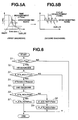
- Figs. 5A and 5B are graphs respectively explaining first and second deterioration diagnoses executed by the diagnosis system of the embodiment.
- Fig. 6 is a flowchart showing a catalyst deterioration diagnosis executed in the embodiment.
- Fig. 7 is a view explaining an exhaust aftertreatment demand.
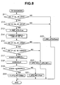
- Fig. 8 is a flowchart showing a first deterioration diagnosis executed at step S1 in Fig. 6.
- Figs. 9A, 9B and 9C are graphs explaining the first deterioration diagnosis of Fig. 8.
- Fig. 10 is a flowchart showing a second deterioration diagnosis executed at step S5 in Fig. 6.
- Fig. 11 is a graph explaining the second deterioration diagnosis of Fig. 10.
- Fig. 12 is a flowchart showing an actual air/fuel ratio calculation process.
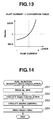
- Fig. 13 is a table showing a relationship between a pump current and the air/fuel ratio.
- Fig. 14 is a flowchart showing a fuel injection quantity calculation process.
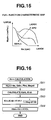
- Fig. 15 is a map showing a fuel injection characteristic.
- Fig. 16 is a flowchart showing an air intake system response time-constant calculation process.
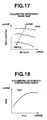
- Fig. 17 is a map showing a volumetric efficiency.
- Fig. 18 is a table showing a volumetric efficiency correction value.
- Fig. 19 is a flowchart showing a cylinder intake fresh air quantity calculation process.
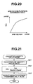
- Fig. 20 is a table showing a relationship between an AFM voltage and an airflow rate.
- Fig. 21 is a flowchart showing an exhaust HC quantity calculation process.
- Figs. 22A and 22B are graphs explaining the deterioration diagnosis using a time measurement.
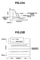
- Figs. 23A and 23B are graphs explaining the deterioration diagnosis using an integral quantity.
- Fig. 1 is a schematic diagram showing an embodiment of the diagnosis system for the exhaust aftertreatment apparatus adapted to an internal combustion engine (diesel engine) according to the present invention.
- an air cleaner 3 Provided in an intake passage 2 of a diesel engine 1 are an air cleaner 3, an airflow meter 4, an intake air compressor 5a of a turbocharger 5, an intercooler 6, an intake air throttle valve 7 and a collector 8, in the order of mention from an upstream side to engine 1. Accordingly, intake air entered through air cleaner 3 is measured by airflow meter 4, compressed by intake air compressor 5a of turbocharger 5, cooled by intercooler 6, and controlled in quantity by intake air throttle valve 7. Further, the air flows into a combustion chamber 9 of each cylinder through collector 8.
- Fuel is pressurized by a common rail type fuel injection system, that is, a high pressure fuel pump 10 and is supplied to a common rail 11, and is then directly injected into each combustion chamber 9 through a fuel injector 10 for each cylinder. Air and fuel supplied into each combustion chamber 9 are properly heated by a glow plug 13 and combusted by a compression ignition. Further, exhaust gas is discharged into an exhaust passage 14.
- a common rail type fuel injection system that is, a high pressure fuel pump 10 and is supplied to a common rail 11, and is then directly injected into each combustion chamber 9 through a fuel injector 10 for each cylinder. Air and fuel supplied into each combustion chamber 9 are properly heated by a glow plug 13 and combusted by a compression ignition. Further, exhaust gas is discharged into an exhaust passage 14.
- a part of exhaust gas flowed into the exhaust gas passage 14 is returned to an intake side of engine 1 through an EGR passage 15 and an EGR valve 16 as EGR (exhaust gas recirculation) gas.
- EGR exhaust gas recirculation
- the other of exhaust gas flows through an exhaust turbine 5b of turbocharger 5 to drive exhaust turbine 5b.
- the exhaust aftertreatment apparatus for engine 1 is disposed downstream of exhaust turbine 5b in exhaust passage 14.
- the exhaust aftertreatment apparatus has a function of purifying exhaust gas by adsorbing and deoxidizing nitrogen oxides (NOx) according to a ratio between an oxide agent and a reducing agent in exhaust gas, which varies at least by an exhaust gas ambient varying means. More specifically, when the exhaust air/fuel ratio is lean, NOx in exhaust gas is trapped in a NOx trap catalyst element 17 of the exhaust aftertreatment apparatus, and when the exhaust air/fuel ratio is rich NOx trapped in NOx trap catalyst element 17 is desorbed and deoxidized at NOx trap catalyst element 17.
- NOx nitrogen oxides
- air/fuel ratio sensors 21 and 22 for detecting air/fuel ratios ⁇ (representing an excess air ratio) in exhaust gas, respectively.
- These upstream and downstream air/fuel ratio sensors 21 and 22 function as first and second exhaust ambience detecting means for detecting a ratio of oxidizing agent and reducing agent in exhaust gas.
- the exhaust aftertreatment apparatus may be arranged, as shown in Fig. 2, such that NOx trap catalyst element 17, on which an oxidizing catalyst is supported, is independently disposed in exhaust passage so as to oxidize the exhaust composition (HC, CO) flowing through NOx trap catalyst element 17. Further, the exhaust aftertreatment apparatus may be arranged, as shown in Fig. 3, to employ NOx trap catalyst element 17 and diesel particulate trap (DPF) 18 for catching exhaust particulate contaminants (soot) which is disposed downstream of NOx trap catalyst element 17. Furthermore, the exhaust aftertreatment apparatus may be arranged, as shown in Fig. 4, such that an oxidizing catalyst 19 is separately disposed upstream of NOx trap catalyst element 17 and DPF 18 is disposed downstream of NOx trap catalyst element 17.
- air/fuel ratio sensors 21 and 22 are disposed at an upstream side and a downstream side of NOx trap catalyst element 17, respectively.
- O 2 sensors 21 and 22 are disposed at an upstream side of oxidizing catalyst 19 and a downstream side of NOx trap catalyst element 17, respectively.
- a pressure difference sensor 23 for detecting a pressure difference between an upstream side pressure and a downstream side pressure of DPF 18, and exhaust gas temperature sensors 24 and 25 for detecting exhaust gas temperatures at inlet and outlet of DPF 18.
- the embodiment according to the present invention has been shown and described so as to calculate a reducing agent quantity in exhaust gas on the basis of the air/fuel ratio sensor output (air/fuel ratio) without directly employing the air/fuel ratio sensor output (air/fuel ratio) as a parameter relating to a ratio between an oxidizing agent and a reducing agent in exhaust gas.
- the first and second exhaust ambience detecting means are constructed so as to comprise HC quantity calculating sections in addition to air/fuel ratio sensors, respectively.
- control unit 30 receives signals from airflow meter 4, air/fuel ratio sensors 21 and 22, an engine speed sensor 31 for detecting engine speed Ne, an accelerator opening sensor 32 for detecting an accelerator opening APO, a water temperature sensor 33 for detecting an engine water temperature Tw, and an intake air pressure sensor 34 for detecting an intake air pressure Pint, in order to control engine 1.
- Control unit 30 outputs a fuel injection command signal to fuel injectors 12, a throttle opening command signal to intake air throttle valve 7 and an EGR valve opening command signal to EGR valve 16, on the basis of the received input signals.
- the fuel injection command signal determines a main injection of fuel injectors 12 and fuel injection quantity and an injection timing of a post injection executed after the main injection, that is, executed during an expansion stroke or exhaust stroke.
- NOx trap catalyst element 17 basically stores NOx during the lean burn operating condition. However, due to the limitation of a NOx trap capacity of NOx trap catalyst element 17, it is necessary to desorb NOx stored in NOx trap catalyst element 17 and to deoxidize NOx at a proper timing before the NOx trap capacity saturates.
- Control unit 30 determines a recovery timing of NOx trap catalyst element 17 on the basis of an engine operation history.
- a rich burn operation (rich spike control) is executed by temporally decreasing an opening of intake air throttle valve 7 or by temporally increasing the fuel injection.
- a method of the rich spike control a method shown in Japanese Published Patent Application No. 7-279718 may be employed, and it will be understood that the method of the rich spike control is not limited to this.
- Control unit 30 is therefore arranged to execute the deterioration diagnosis of NOx trap catalyst element by utilizing an O 2 storage function of NOx trap catalyst element 17.
- the deterioration diagnosis employed in the embodiment of the present invention includes a first deterioration diagnosis which is easily executed under a normal engine operating condition, and a second deterioration diagnosis which is executed when the first deterioration diagnosis result is that the possibility of the deterioration is high, and which is capable of obtain a high-accuracy diagnosis result.
- the first deterioration diagnosis is executed under a normal operating condition and when the exhaust ambience is changed to rich side or lean side, that is, when the engine operating state is changed from a lean burn operation to a rich burn operation, or changed from the rich burn operation to the lean burn operation. More specifically, when the rich spike control is executed, the first deterioration diagnosis is executed.
- the technique of the first deterioration diagnosis is arranged to measure a time period ⁇ Time (shown in Fig. 22) from a first moment that the air/fuel ratio ⁇ or HC quantity at the upstream side of catalyst 17 is changed to a predetermined value to a second moment that the air/fuel ratio ⁇ or HC quantity at the downstream side of catalyst 17 reaches the predetermined value with reference to a graph of Fig. 5A, or to calculate an integral quantity ( ⁇ (HC) of a difference between the upstream side and downstream side air/fuel ratios ⁇ or HC quantities during the time period ⁇ Time. Further, on the basis of the obtained time period ⁇ Time or the integral quantity, a deterioration of NOx trap catalyst element is diagnosed.
- the second deterioration diagnosis is executed upon changing the engine operation mode to a diagnosis operation mode, that is, to the stoichiometric air/fuel ratio operating condition, when the result of the first deterioration diagnosis indicates that NOx trap catalyst element 17 is in a deterioration condition.
- the technique of the second deterioration diagnosis is arranged to measure an inversion cycle TCHK of a feedback quantity ( ⁇ ) during a feedback control while feedback controlling an exhaust air/fuel ratio at a value near the stoichiometric air/fuel ratio on the basis of the output of the downstream side air/fuel ratio sensor 22. Further on the basis of the obtained inversion cycle TCHK, a deterioration of NOx trap catalyst element 17 is diagnosed.
- the method of measuring the inversion cycle TCHK of the feedback quantity during the air/fuel ratio feedback control is commonly known, and is particularly disclosed in Japanese Published Patent Application No. 10-121943. Therefore, the explanation thereof is omitted herein.
- the catalyst deterioration diagnosis during the rich spike control is simple. However, since this deterioration diagnosis is executed during a transient operating condition, it is difficult to obtain a diagnosis result with high accuracy. On the other hand, although in view of accuracy it is preferable to employ the method of diagnosing the deterioration on the basis of the inversion cycle of the air/fuel ratio feedback control as to the downstream side air/fuel ratio, this latter diagnosis has to be executed under the stoichiometric air/fuel ratio condition. Accordingly, the latter diagnosis is not preferable in view of fuel consumption.
- the first deterioration diagnosis a simple catalyst deterioration diagnosis executed during the rich spike control is adopted. Further, when the result of the first deterioration diagnosis executed under a condition of setting the diagnosis threshold at a relatively severe value indicative that there is a deterioration tendency of the catalyst, the second diagnosis, which is a high-accuracy deterioration diagnosis executed on the basis of the inversion cycle of the air/fuel ration feedback control at a value near the stoichiometric air/fuel ratio, is executed.
- Fig. 6 is the main flowchart of the catalyst deterioration diagnosis.
- control unit 30 determines whether or not a rich spike control is now being executed by checking a flag Frich indicative of an execution state of the rich spike control for recovering NOx trap catalyst element 17.
- flag Frich indicative of an execution state of the rich spike control for recovering NOx trap catalyst element 17.
- control unit 30 executes the first deterioration diagnosis (1st Diagnosis) shown by a flowchart in Fig. 8 to obtain a first deterioration diagnosis result F_ATS_NG1.
- control unit 30 determines whether or not first diagnosis result F_ATS_NG1 is true.
- the determination at step S3 is affirmative, that is, when first diagnosis result F_ATS_NG1 is true indicative that NOx trap catalyst element in the deteriorated condition
- the program proceeds to step S4.
- the determination at step S3 is negative, that is, when first diagnosis result F_ATS_NG1 is false, the present routine is terminated.
- control unit 30 sets an exhaust aftertreatment demand flag ATSstate at 3 to transit the present engine operation to the stoichiometric air/fuel ratio control for the purpose of executing a second deterioration diagnosis.
- the explanation of the exhaust aftertreatment demand flag ATSstate is discussed later.
- control unit 30 obtains a second deterioration diagnosis result F_ATS_NG2 by executing the second deterioration diagnosis (2nd Diagnosis) shown by a flowchart in Fig. 10.
- control unit 30 determines whether or not second diagnosis result F_ATS_NG2 is true.
- Fig. 7 shows an explanatory view for explaining the exhaust aftertreatment demand flag ATSstate.
- control unit 30 sets the flag ATSstate at 1 indicative of a normal diesel operation mode so that air/fuel ratio ⁇ is set to be greater than or equal to 1.4 ( ⁇ ⁇ 1.4) to execute a lean burn operation.
- the first deterioration diagnosis is executed.
- control unit 30 sets ATSstate at 6 to execute an operation for avoiding such damage-by-fire for a predetermined time. Thereafter, the operation returns to a normal operation.
- Fig. 8 shows the flowchart of the first deterioration diagnosis executed at step S2 of the flowchart in Fig. 6, and Fig. 9 shows the situation of the first deterioration diagnosis.
- control unit 30 determines whether or not HC quantity HC_F at an upstream side of NOx trap catalyst element 17 is smaller than a predetermined value SL_HC_SF# in order to check whether the rich burn control is being executed.
- control unit 30 determines whether or not HC quantity HC_R at an downstream side of NOx trap catalyst element 17 is smaller than a predetermined value SL_HC_SR1# in order to check whether the rich burn control is being executed.
- HC quantity Hydro Carbon quantity
- control unit 30 calculates HC integral quantity KOBDHC, which is a difference between the upstream side HC quantity HC_F and downstream side HC quantity HC_R using the following expression (1).
- KOBDHC KOBDHCn-1 + (HC_F - HC_R)
- control unit 30 determines whether or not downstream side HC quantity HC_R is smaller than a predetermined quantity SL_HC_SR2# to determine whether or not the stoichiometric air/fuel ratio maintaining period is terminated.
- control unit 30 determines whether or not the difference
- step S17 When both of the determinations at steps S15 and S16 are affirmative (True), the program proceeds to step S17.
- step S15 or the determination at step S16 is negative (False)
- control unit 30 determines whether or not the final HC integral quantity KOBDF is greater than a predetermined diagnosis threshold KOBDFSL#.
- Fig. 10 is a flowchart of the second deterioration diagnosis execute at step S5 of the flowchart shown in Fig. 6, and Fig. 11 shows a concrete operation of the second deterioration diagnosis.
- control unit 31 determines whether the exhaust aftertreatment demand flag ATSstate is 3 or 4 to determine whether the engine operating condition is in the vicinity of the stoichiometric air/fuel ratio.
- control unit 30 determines whether or not the air/fuel ratio Rlambr is converging at the target air/fuel ratio by checking whether an absolute value
- step S31 and S32 When both of the determinations at step S31 and S32 are affirmative (True), the program proceeds to step S33. When either the determination at step S31 or the determination at step S32 is negative (False), the present routine is terminated.
- control unit 30 reads an inversion cycle TCHK of the air/fuel ratio feedback control and determines whether or not the inversion cycle TCHK is smaller than a diagnosis threshold SL_TCHK#.
- the program proceeds to step S34 wherein control unit 30 determines that the catalyst is abnormal. Thereafter, the present routine is terminated.
- Fig. 12 shows a flowchart for calculating actual air/fuel ratio (actual ⁇ ) from an output of a wide range type air/fuel ratio sensor. Both outputs of the upstream side and downstream side sensors for NOx trap catalyst element 17 are similarly employed to calculate the respective actual air/fuel ratios thereof.
- control unit 30 reads a pump current of each air/fuel ratio sensor.
- control unit 30 converts the pump current into the actual air/fuel ratio Rlamb0 using a table shown in Fig. 13.
- control unit 30 obtains the final air/fuel ratios (upstream side air/fuel ration Rlambf and downstream side air/fuel ratio Rlambr) by executing a weighted average processing.
- Fig. 14 shows a flowchart employed for calculating a target acceleration demand fuel injection quantity Qfdrv.
- control unit 30 reads engine speed Ne and accelerator opening APO.
- control unit 30 retrieves a basic fuel injection quanity Mqdrv from a map shown in Fig. 15 on the basis of engine speed Ne and accelerator opening APO.
- control unit 30 calculates an idling correction quantity Qfisc for an idling speed control.
- control unit 30 obtains target acceleration demand fuel injection quantity Qfdrv by adding idling correction quantity Qfisc to basic fuel injection quantity Mqdrv. Thereafter, the present routine is terminated.
- Fig. 16 is a flowchart wherein a response time constant equivalent value Kkin of an air intake system.
- control unit 30 reads engine speed Ne, target acceleration demand fuel injection quantity Qfdrv, intake air pressure Pint and EGR ratio Megrd.
- control unit 30 calculates a volumetric efficiency basic value Kinb from engine speed Ne and target acceleration demand fuel injection quantity Qfdrv using a map shown in Fig. 17, and calculates volumetric efficiency intake pressure correction value Kinh from intake pressure Pint using a table shown in Fig. 18.
- control unit 30 calculates volumetric efficiency equivalent value Kin from volumetric efficiency basic value Kinb, volumetric efficiency intake pressure correction value Kinh and EGR ratio Megrd using the following expression (2).
- Kin Kinb ⁇ Kinh ⁇ 1/(1Megrd/100)
- control unit 30 calculates a response time constant equivalent value Kkin of the air intake system by multiplying volumetric efficiency equivalent value Kin by a volume ratio KVOL. Thereafter, the present routine is terminated.
- volume ratio KVOL is a ratio (Vc/Vm) between an intake system volume Vm and a cylinder stroke volume Vc.
- Fig. 19 is a flowchart for calculating a cylinder intake fresh air quantity Qac.
- control unit 30 reads an output voltage of airflow meter (AFM).
- control unit 30 converts the output voltage into an intake air quantity Qas using a table shown in Fig. 20.
- control unit 30 executes a weighted average process of intake air quantity Qas to obtain a value Qas0.
- control unit 30 reads engine speed Ne.
- control unit 30 calculates per-cylinder intake air quantity Qac0 from intake air quantity Qas0, engine speed Ne and a constant KCON# using the following expression (3).
- Qac0 Qas0/Ne ⁇ KCON#
- control unit 30 calculates a cylinder intake fresh air quantity Qac by executing a delay processing from response time constant equivalent value Kin and collector inlet fresh air quantity Qacn using the following expression (4).
- Qac Qac n-1 ⁇ (1-Kkin) + Qac n ⁇ Kkin
- Fig. 21 is a flowchart for calculating an exhaust system HC quantity (reducing agent quantity). Both outputs of the upstream side and downstream side sensors for NOx trap catalyst element 17 are similarly employed to calculate the respective exhaust system HC quantities thereof.
- control unit 30 reads cylinder intake fresh air quantity Qac, air/fuel ratio Rlamb (Rlambf and Rlambr).
- control unit 30 calculates HC quantity using the following expression (5).
- HC Qac/(Blmab# ⁇ Ralmb) where Blmab# is a constant.
- control unit 30 executes the weighted average processing of HC quantity obtained at step S82 to obtain the final HC quantity and sets the upstream side and downstream side HC quantity of NOx trap catalyst element as HC_F and HC_R, respectively.
- the first deterioration diagnosis is executed under a normal engine operating condition wherein the exhaust ambience is changed to rich side or lean side, and diagnoses the deterioration of the exhaust aftertreatment apparatus from the detection result change between the first and second exhaust ambience detecting means respectively provided at the upstream side and the downstream side of the exhaust aftertreatment apparatus.
- the second deterioration diagnosis is executed.
- the engine operating condition is changed to a diagnosis operating condition.
- the second deterioration diagnosis is arranged to diagnose the exhaust aftertreatment apparatus from a change of the detection result of the second exhaust ambience detecting means.
- the diagnosis of the exhaust aftertreatment apparatus is easily executed without deteriorating the engine performance.
- the first deterioration diagnosis is arranged to calculate the integral of a difference between the output of the first exhaust ambience detecting means and the output of the second exhaust ambience detecting means during a period from a first moment that the output of the first exhaust ambience detecting means varies to a predetermined value to a second moment that the output of the second exhaust ambience detecting means also varies to the predetermined value, and to diagnose the deterioration of the exhaust aftertreatment apparatus on the basis of the obtained integral quantity.
- This arrangement largely improves the accuracy of the diagnosis.
- the diagnosis method of calculating the integral quantity ⁇ ( ⁇ HC) and diagnosing the deterioration of the exhaust aftertreatment apparatus on the basis of this integral quantity improves the accuracy of the diagnosis for the reasons that the fluctuation is small even if the control of the air/fuel ratio during the rich spike control fluctuates, as shown in Figs. 23A and 23B.
- the second deterioration diagnosis of the embodiment according to the present invention is arranged to execute the deterioration diagnosis by transiting the engine operation to the stoichiometric air/fuel ratio control, it becomes possible to accurately diagnose the deterioration of the exhaust aftertreatment apparatus.
- the second deterioration diagnosis of the embodiments according to the present invention is arranged to execute the deterioration diagnosis by feedback controlling the exhaust air/fuel ratio at ratios near the stoichiometric air/fuel ratio on the basis of the output of the second exhaust ambience detecting means, by measuring the inversion cycle of the feedback quantity during the feedback control, and by diagnosing the deterioration of the exhaust aftertreatment apparatus on the basis of the inversion cycle.
- This arrangement enables the high-accuracy diagnosis.
- the advantages of the diagnosis system is increased due to the separation of the diagnosis into two stages. That is, in case of a gasoline engine, at least in a high-load operation area, the engine is operated in the vicinity of the stoichiometric air/fuel ratio, and therefore, it is possible to firstly execute the diagnosis on the basis of the inversion cycle of the feedback quantity during the feedback quantity.
Landscapes
- Engineering & Computer Science (AREA)
- Chemical & Material Sciences (AREA)
- Combustion & Propulsion (AREA)
- Mechanical Engineering (AREA)
- General Engineering & Computer Science (AREA)
- Chemical Kinetics & Catalysis (AREA)
- Exhaust Gas After Treatment (AREA)
- Electrical Control Of Air Or Fuel Supplied To Internal-Combustion Engine (AREA)
- Combined Controls Of Internal Combustion Engines (AREA)
Applications Claiming Priority (2)
| Application Number | Priority Date | Filing Date | Title |
|---|---|---|---|
| JP2003099656A JP4092486B2 (ja) | 2003-04-02 | 2003-04-02 | 内燃機関の排気後処理装置の診断装置 |
| JP2003099656 | 2003-04-02 |
Publications (3)
| Publication Number | Publication Date |
|---|---|
| EP1464816A2 true EP1464816A2 (de) | 2004-10-06 |
| EP1464816A3 EP1464816A3 (de) | 2005-05-04 |
| EP1464816B1 EP1464816B1 (de) | 2011-11-23 |
Family
ID=32844696
Family Applications (1)
| Application Number | Title | Priority Date | Filing Date |
|---|---|---|---|
| EP04008006A Expired - Lifetime EP1464816B1 (de) | 2003-04-02 | 2004-04-01 | Diagnosesystem für eine Abgasnachbehandlungsanlage einer Brennkraftmaschine |
Country Status (4)
| Country | Link |
|---|---|
| US (1) | US7162860B2 (de) |
| EP (1) | EP1464816B1 (de) |
| JP (1) | JP4092486B2 (de) |
| CN (1) | CN100362219C (de) |
Cited By (2)
| Publication number | Priority date | Publication date | Assignee | Title |
|---|---|---|---|---|
| EP1734242A1 (de) * | 2005-06-17 | 2006-12-20 | Ford Global Technologies, LLC | Diagnoseverfahren für eine Vorkatlambdasonde und ein Katalysator eines Abgassystems |
| FR3012171A1 (fr) * | 2013-10-23 | 2015-04-24 | Renault Sa | Procede de diagnostic d'un piege a oxydes d'azote et dispositif associe |
Families Citing this family (29)
| Publication number | Priority date | Publication date | Assignee | Title |
|---|---|---|---|---|
| US7469177B2 (en) * | 2005-06-17 | 2008-12-23 | Honeywell International Inc. | Distributed control architecture for powertrains |
| WO2007008121A1 (en) * | 2005-07-07 | 2007-01-18 | Volvo Lastvagnar Ab | Method, device and computer program product for diagnosing of at least one exhaust emission control unit |
| JP4718613B2 (ja) * | 2005-09-29 | 2011-07-06 | ボルボ ラストバグナー アーベー | 排気後処理システムの診断方法 |
| JP4742837B2 (ja) * | 2005-12-07 | 2011-08-10 | 日産自動車株式会社 | 内燃機関の触媒劣化診断装置および診断方法 |
| JP4335249B2 (ja) * | 2006-12-04 | 2009-09-30 | 三菱電機株式会社 | 内燃機関の制御装置 |
| US7771113B2 (en) * | 2007-06-29 | 2010-08-10 | Cummins Filtration Ip, Inc | Sensor rationality diagnostic |
| JP5125298B2 (ja) * | 2007-08-03 | 2013-01-23 | 日産自動車株式会社 | 内燃機関の燃料供給制御装置 |
| JP4483972B2 (ja) * | 2008-04-14 | 2010-06-16 | トヨタ自動車株式会社 | 排気浄化システムの故障診断装置 |
| DE102008043706B4 (de) * | 2008-11-13 | 2013-09-05 | Ford Global Technologies, Llc | Verfahren zur Reduktion von Stickoxiden in Abgasen |
| DE102009054817A1 (de) * | 2009-12-17 | 2011-06-22 | Ford Global Technologies, LLC, Mich. | Verfahren und Vorrichtung zur "On-Board"-Felerdiagnose im Betrieb eines Verbrennungsmotors |
| WO2011135710A1 (ja) * | 2010-04-30 | 2011-11-03 | トヨタ自動車株式会社 | 内燃機関の触媒劣化検出装置及び触媒劣化検出方法 |
| KR101393704B1 (ko) * | 2012-05-31 | 2014-05-13 | 한국기계연구원 | 산화 촉매의 이상 진단 장치 및 방법 |
| US20140090374A1 (en) * | 2012-10-03 | 2014-04-03 | Caterpollar Inc. | Exhaust aftertreatment system and method |
| DE102012025002A1 (de) | 2012-12-20 | 2014-06-26 | Volkswagen Aktiengesellschaft | Verfahren zur Diagnose eines Abgaskatalysators, Diagnoseeinrichtung sowie Kraftfahrzeug mit einer solchen |
| JP2019105259A (ja) | 2017-12-14 | 2019-06-27 | トヨタ自動車株式会社 | 還元剤添加装置の異常診断装置 |
| JP7234956B2 (ja) * | 2020-02-03 | 2023-03-08 | トヨタ自動車株式会社 | 空燃比検出装置の異常検出装置 |
| US11636870B2 (en) | 2020-08-20 | 2023-04-25 | Denso International America, Inc. | Smoking cessation systems and methods |
| US11932080B2 (en) | 2020-08-20 | 2024-03-19 | Denso International America, Inc. | Diagnostic and recirculation control systems and methods |
| US12269315B2 (en) | 2020-08-20 | 2025-04-08 | Denso International America, Inc. | Systems and methods for measuring and managing odor brought into rental vehicles |
| US11813926B2 (en) | 2020-08-20 | 2023-11-14 | Denso International America, Inc. | Binding agent and olfaction sensor |
| US11881093B2 (en) | 2020-08-20 | 2024-01-23 | Denso International America, Inc. | Systems and methods for identifying smoking in vehicles |
| US11760170B2 (en) | 2020-08-20 | 2023-09-19 | Denso International America, Inc. | Olfaction sensor preservation systems and methods |
| US12017506B2 (en) | 2020-08-20 | 2024-06-25 | Denso International America, Inc. | Passenger cabin air control systems and methods |
| US12251991B2 (en) | 2020-08-20 | 2025-03-18 | Denso International America, Inc. | Humidity control for olfaction sensors |
| US11828210B2 (en) | 2020-08-20 | 2023-11-28 | Denso International America, Inc. | Diagnostic systems and methods of vehicles using olfaction |
| US12377711B2 (en) | 2020-08-20 | 2025-08-05 | Denso International America, Inc. | Vehicle feature control systems and methods based on smoking |
| US11760169B2 (en) | 2020-08-20 | 2023-09-19 | Denso International America, Inc. | Particulate control systems and methods for olfaction sensors |
| JP7447823B2 (ja) * | 2021-01-07 | 2024-03-12 | トヨタ自動車株式会社 | エンジン制御装置 |
| JP2023042206A (ja) * | 2021-09-14 | 2023-03-27 | ヤマハ発動機株式会社 | 船舶推進機およびそれを備える船舶 |
Citations (5)
| Publication number | Priority date | Publication date | Assignee | Title |
|---|---|---|---|---|
| EP0636771A1 (de) | 1993-07-31 | 1995-02-01 | Lucas Industries Public Limited Company | Verfahren und Vorrichtung zur Überwachung der Funktionsfähigkeit eines Katalysators |
| JPH07279718A (ja) | 1994-04-12 | 1995-10-27 | Toyota Motor Corp | ディーゼル機関の排気浄化装置 |
| JPH10121943A (ja) | 1996-10-21 | 1998-05-12 | Honda Motor Co Ltd | 内燃機関の触媒劣化判定装置 |
| JP2001073747A (ja) | 1999-09-01 | 2001-03-21 | Honda Motor Co Ltd | 内燃機関の排気浄化装置 |
| JP2002038929A (ja) | 2000-07-24 | 2002-02-06 | Toyota Motor Corp | 内燃機関の排気浄化装置 |
Family Cites Families (16)
| Publication number | Priority date | Publication date | Assignee | Title |
|---|---|---|---|---|
| USRE28051E (en) * | 1970-04-09 | 1974-06-18 | Torque traksmitting device | |
| JPH0417758A (ja) * | 1990-05-08 | 1992-01-22 | Honda Motor Co Ltd | 内燃機関の三元触媒の劣化検出方法 |
| JP2626384B2 (ja) * | 1991-12-16 | 1997-07-02 | トヨタ自動車株式会社 | 触媒劣化判別装置 |
| JP3074975B2 (ja) * | 1992-11-04 | 2000-08-07 | スズキ株式会社 | 内燃機関の触媒劣化判定装置 |
| JP3149714B2 (ja) * | 1994-12-28 | 2001-03-26 | 日産自動車株式会社 | 内燃機関の触媒劣化診断装置 |
| US5887421A (en) * | 1996-03-18 | 1999-03-30 | Toyota Jidosha Kabushiki Kaisha | Apparatus for detecting the deterioration of a three-way catalytic converter for an internal combustion engine |
| EP0892159A3 (de) * | 1997-07-17 | 2000-04-26 | Hitachi, Ltd. | Abgasreiningungsvorrichtung und -Verfahren einer Brennkraftmaschine |
| GB9717034D0 (en) * | 1997-08-13 | 1997-10-15 | Johnson Matthey Plc | Improvements in emissions control |
| US6050128A (en) * | 1998-05-28 | 2000-04-18 | Ford Global Technologies, Inc. | Catalyst deterioration monitoring |
| US6467254B1 (en) * | 2000-01-20 | 2002-10-22 | Ford Global Technologies, Inc. | Diagnostic system for detecting catalyst failure using switch ratio |
| JP4889873B2 (ja) * | 2000-09-08 | 2012-03-07 | 日産自動車株式会社 | 排気ガス浄化システム、これに用いる排気ガス浄化触媒及び排気浄化方法 |
| DE10054005A1 (de) * | 2000-11-01 | 2002-05-08 | Daimler Chrysler Ag | Verfahren zum Betrieb einer Abgasreinigungsanlage mit Stickoxidspeicher |
| JP2002147224A (ja) * | 2000-11-08 | 2002-05-22 | Honda Motor Co Ltd | 吸着材の状態判定装置 |
| EP1365137B9 (de) * | 2001-02-26 | 2006-07-12 | Mitsubishi Jidosha Kogyo Kabushiki Kaisha | Abgasreiniger für brennkraftmaschinen |
| US6594985B2 (en) * | 2001-06-19 | 2003-07-22 | Ford Global Technologies, Inc. | Exhaust gas aftertreatment device efficiency estimation |
| US6813884B2 (en) * | 2002-01-29 | 2004-11-09 | Ford Global Technologies, Llc | Method of treating diesel exhaust gases |
-
2003
- 2003-04-02 JP JP2003099656A patent/JP4092486B2/ja not_active Expired - Fee Related
-
2004
- 2004-04-01 US US10/814,602 patent/US7162860B2/en not_active Expired - Fee Related
- 2004-04-01 EP EP04008006A patent/EP1464816B1/de not_active Expired - Lifetime
- 2004-04-02 CN CNB200410033367XA patent/CN100362219C/zh not_active Expired - Fee Related
Patent Citations (5)
| Publication number | Priority date | Publication date | Assignee | Title |
|---|---|---|---|---|
| EP0636771A1 (de) | 1993-07-31 | 1995-02-01 | Lucas Industries Public Limited Company | Verfahren und Vorrichtung zur Überwachung der Funktionsfähigkeit eines Katalysators |
| JPH07279718A (ja) | 1994-04-12 | 1995-10-27 | Toyota Motor Corp | ディーゼル機関の排気浄化装置 |
| JPH10121943A (ja) | 1996-10-21 | 1998-05-12 | Honda Motor Co Ltd | 内燃機関の触媒劣化判定装置 |
| JP2001073747A (ja) | 1999-09-01 | 2001-03-21 | Honda Motor Co Ltd | 内燃機関の排気浄化装置 |
| JP2002038929A (ja) | 2000-07-24 | 2002-02-06 | Toyota Motor Corp | 内燃機関の排気浄化装置 |
Cited By (3)
| Publication number | Priority date | Publication date | Assignee | Title |
|---|---|---|---|---|
| EP1734242A1 (de) * | 2005-06-17 | 2006-12-20 | Ford Global Technologies, LLC | Diagnoseverfahren für eine Vorkatlambdasonde und ein Katalysator eines Abgassystems |
| FR3012171A1 (fr) * | 2013-10-23 | 2015-04-24 | Renault Sa | Procede de diagnostic d'un piege a oxydes d'azote et dispositif associe |
| WO2015059374A1 (fr) * | 2013-10-23 | 2015-04-30 | Renault S.A.S. | Procede de diagnostic d'un piege a oxydes d'azote et dispositif associe |
Also Published As
| Publication number | Publication date |
|---|---|
| US20040250609A1 (en) | 2004-12-16 |
| CN1536206A (zh) | 2004-10-13 |
| JP4092486B2 (ja) | 2008-05-28 |
| JP2004308455A (ja) | 2004-11-04 |
| EP1464816A3 (de) | 2005-05-04 |
| US7162860B2 (en) | 2007-01-16 |
| EP1464816B1 (de) | 2011-11-23 |
| CN100362219C (zh) | 2008-01-16 |
Similar Documents
| Publication | Publication Date | Title |
|---|---|---|
| US7162860B2 (en) | Diagnosis system of exhaust aftertreatment apparatus for internal combustion engine | |
| JP3873904B2 (ja) | 内燃機関の排気浄化装置 | |
| JP4952847B2 (ja) | 内燃機関の制御装置 | |
| US7325393B2 (en) | Deterioration diagnosing device and diagnosing method for exhaust gas purification catalyst | |
| US7168237B2 (en) | Deterioration diagnosing device and diagnosing method for exhaust gas purification catalyst | |
| US20170362979A1 (en) | EXHAUST PURIFICATION SYSTEM AND METHOD FOR RESTORING NOx PURIFICATION CAPACITY | |
| JP4285141B2 (ja) | ディーゼルエンジンの燃料噴射制御装置 | |
| CN101501309B (zh) | 催化剂监测系统和方法 | |
| KR100649403B1 (ko) | NOx 흡장 촉매의 흡장량 추정 장치 및 흡장량 추정 방법 | |
| JP4092485B2 (ja) | 排気ガス浄化触媒の劣化診断装置 | |
| JP4380354B2 (ja) | 内燃機関の添加弁異常診断装置 | |
| JP4154589B2 (ja) | 内燃機関の燃焼制御装置 | |
| JP6498537B2 (ja) | 内燃機関の制御装置 | |
| JP4244751B2 (ja) | 内燃機関の燃焼制御方法及び燃焼制御装置 | |
| JP5308875B2 (ja) | 内燃機関の排ガス浄化装置 | |
| JP2006183525A (ja) | 内燃機関の排気浄化装置 | |
| JP4103820B2 (ja) | 触媒の劣化診断装置 | |
| JP2006183495A (ja) | 内燃機関の排気浄化装置 |
Legal Events
| Date | Code | Title | Description |
|---|---|---|---|
| PUAI | Public reference made under article 153(3) epc to a published international application that has entered the european phase |
Free format text: ORIGINAL CODE: 0009012 |
|
| 17P | Request for examination filed |
Effective date: 20040401 |
|
| AK | Designated contracting states |
Kind code of ref document: A2 Designated state(s): AT BE BG CH CY CZ DE DK EE ES FI FR GB GR HU IE IT LI LU MC NL PL PT RO SE SI SK TR |
|
| AX | Request for extension of the european patent |
Extension state: AL HR LT LV MK |
|
| PUAL | Search report despatched |
Free format text: ORIGINAL CODE: 0009013 |
|
| AK | Designated contracting states |
Kind code of ref document: A3 Designated state(s): AT BE BG CH CY CZ DE DK EE ES FI FR GB GR HU IE IT LI LU MC NL PL PT RO SE SI SK TR |
|
| AX | Request for extension of the european patent |
Extension state: AL HR LT LV MK |
|
| RIC1 | Information provided on ipc code assigned before grant |
Ipc: 7F 01N 11/00 B Ipc: 7F 02D 41/14 A |
|
| AKX | Designation fees paid |
Designated state(s): DE FR GB |
|
| GRAP | Despatch of communication of intention to grant a patent |
Free format text: ORIGINAL CODE: EPIDOSNIGR1 |
|
| GRAS | Grant fee paid |
Free format text: ORIGINAL CODE: EPIDOSNIGR3 |
|
| GRAA | (expected) grant |
Free format text: ORIGINAL CODE: 0009210 |
|
| AK | Designated contracting states |
Kind code of ref document: B1 Designated state(s): DE FR GB |
|
| REG | Reference to a national code |
Ref country code: GB Ref legal event code: FG4D |
|
| REG | Reference to a national code |
Ref country code: DE Ref legal event code: R096 Ref document number: 602004035374 Country of ref document: DE Effective date: 20120202 |
|
| PLBE | No opposition filed within time limit |
Free format text: ORIGINAL CODE: 0009261 |
|
| STAA | Information on the status of an ep patent application or granted ep patent |
Free format text: STATUS: NO OPPOSITION FILED WITHIN TIME LIMIT |
|
| 26N | No opposition filed |
Effective date: 20120824 |
|
| REG | Reference to a national code |
Ref country code: DE Ref legal event code: R097 Ref document number: 602004035374 Country of ref document: DE Effective date: 20120824 |
|
| PGFP | Annual fee paid to national office [announced via postgrant information from national office to epo] |
Ref country code: GB Payment date: 20140326 Year of fee payment: 11 |
|
| PGFP | Annual fee paid to national office [announced via postgrant information from national office to epo] |
Ref country code: DE Payment date: 20140417 Year of fee payment: 11 Ref country code: FR Payment date: 20140409 Year of fee payment: 11 |
|
| REG | Reference to a national code |
Ref country code: DE Ref legal event code: R119 Ref document number: 602004035374 Country of ref document: DE |
|
| GBPC | Gb: european patent ceased through non-payment of renewal fee |
Effective date: 20150401 |
|
| PG25 | Lapsed in a contracting state [announced via postgrant information from national office to epo] |
Ref country code: GB Free format text: LAPSE BECAUSE OF NON-PAYMENT OF DUE FEES Effective date: 20150401 Ref country code: DE Free format text: LAPSE BECAUSE OF NON-PAYMENT OF DUE FEES Effective date: 20151103 |
|
| REG | Reference to a national code |
Ref country code: FR Ref legal event code: ST Effective date: 20151231 |
|
| PG25 | Lapsed in a contracting state [announced via postgrant information from national office to epo] |
Ref country code: FR Free format text: LAPSE BECAUSE OF NON-PAYMENT OF DUE FEES Effective date: 20150430 |