EP1464854A2 - Teleskopische Antriebswellekupplung für Kraftfahrzeug - Google Patents
Teleskopische Antriebswellekupplung für Kraftfahrzeug Download PDFInfo
- Publication number
- EP1464854A2 EP1464854A2 EP04251894A EP04251894A EP1464854A2 EP 1464854 A2 EP1464854 A2 EP 1464854A2 EP 04251894 A EP04251894 A EP 04251894A EP 04251894 A EP04251894 A EP 04251894A EP 1464854 A2 EP1464854 A2 EP 1464854A2
- Authority
- EP
- European Patent Office
- Prior art keywords
- members
- wedge member
- slip joint
- cap
- driveshaft
- Prior art date
- Legal status (The legal status is an assumption and is not a legal conclusion. Google has not performed a legal analysis and makes no representation as to the accuracy of the status listed.)
- Withdrawn
Links
Images

Classifications
-
- F—MECHANICAL ENGINEERING; LIGHTING; HEATING; WEAPONS; BLASTING
- F16—ENGINEERING ELEMENTS AND UNITS; GENERAL MEASURES FOR PRODUCING AND MAINTAINING EFFECTIVE FUNCTIONING OF MACHINES OR INSTALLATIONS; THERMAL INSULATION IN GENERAL
- F16C—SHAFTS; FLEXIBLE SHAFTS; ELEMENTS OR CRANKSHAFT MECHANISMS; ROTARY BODIES OTHER THAN GEARING ELEMENTS; BEARINGS
- F16C3/00—Shafts; Axles; Cranks; Eccentrics
- F16C3/02—Shafts; Axles
- F16C3/03—Shafts; Axles telescopic
- F16C3/035—Shafts; Axles telescopic with built-in bearings
-
- F—MECHANICAL ENGINEERING; LIGHTING; HEATING; WEAPONS; BLASTING
- F16—ENGINEERING ELEMENTS AND UNITS; GENERAL MEASURES FOR PRODUCING AND MAINTAINING EFFECTIVE FUNCTIONING OF MACHINES OR INSTALLATIONS; THERMAL INSULATION IN GENERAL
- F16C—SHAFTS; FLEXIBLE SHAFTS; ELEMENTS OR CRANKSHAFT MECHANISMS; ROTARY BODIES OTHER THAN GEARING ELEMENTS; BEARINGS
- F16C3/00—Shafts; Axles; Cranks; Eccentrics
- F16C3/02—Shafts; Axles
- F16C3/03—Shafts; Axles telescopic
-
- Y—GENERAL TAGGING OF NEW TECHNOLOGICAL DEVELOPMENTS; GENERAL TAGGING OF CROSS-SECTIONAL TECHNOLOGIES SPANNING OVER SEVERAL SECTIONS OF THE IPC; TECHNICAL SUBJECTS COVERED BY FORMER USPC CROSS-REFERENCE ART COLLECTIONS [XRACs] AND DIGESTS
- Y10—TECHNICAL SUBJECTS COVERED BY FORMER USPC
- Y10T—TECHNICAL SUBJECTS COVERED BY FORMER US CLASSIFICATION
- Y10T403/00—Joints and connections
- Y10T403/32—Articulated members
- Y10T403/32254—Lockable at fixed position
- Y10T403/32467—Telescoping members
- Y10T403/32475—Telescoping members having detent
- Y10T403/32501—Cam or wedge
Definitions
- the invention relates in general to driveshaft assemblies, such as are commonly found in the drive train systems of most vehicles.
- this invention relates to an improved structure for a sliding spline type of slip joint for use in such a vehicular driveshaft assembly.
- Drive train systems are widely used for generating power from a source and for transferring such power from the source to a driven mechanism.
- the source generates rotational power, and such rotational power is transferred from the source to a rotatably driven mechanism.
- an engine/transmission assembly generates rotational power, and such rotational power is transferred from an output shaft of the engine/transmission assembly through a driveshaft assembly to an input shaft of an axle assembly so as to rotatably drive the wheels of the vehicle.
- a typical driveshaft assembly includes a hollow cylindrical driveshaft tube having a pair of end fittings, such as a pair of tube yokes, secured to the front and rear ends thereof.
- the front end fitting forms a portion of a front universal joint that connects the output shaft of the engine/transmission assembly to the front end of the driveshaft tube.
- the rear end fitting forms a portion of a rear universal joint that connects the rear end of the driveshaft tube to the input shaft of the axle assembly.
- the front and rear universal joints provide a rotational driving connection from the output shaft of the engine/transmission assembly through the driveshaft tube to the input shaft of the axle assembly, while accommodating a limited amount of angular misalignment between the rotational axes of these three shafts.
- a typical slip joint in the driveshaft assembly includes first and second members that have respective structures formed thereon that cooperate with one another for concurrent rotational movement, while permitting a limited amount of axial movement to occur therebetween.
- a typical sliding spline type of slip joint includes male and female members having respective pluralities of splines formed thereon.
- the male member is generally cylindrical in shape and has a plurality of outwardly extending splines formed on the outer surface thereof.
- the male member may be formed integrally with or secured to a first end of the driveshaft assembly described above.
- the female member is generally hollow and cylindrical in shape and has a plurality of inwardly extending splines formed on the inner surface thereof.
- the female member may be formed integrally with or secured to a second end of the driveshaft assembly described above.
- the male member is inserted within the female member such that the outwardly extending splines of the male member cooperate with the inwardly extending splines of the female member.
- the male and female members are connected together for concurrent rotational movement.
- the outwardly extending splines of the male member can slide relative to the inwardly extending splines of the female member to allow a limited amount of relative axial movement to occur between the engine/transmission assembly and the axle assembly of the drive train system.
- the invention relates to an improved structure for a slip joint, such as is commonly used in a driveshaft assembly of a vehicular drive train system, that minimizes or eliminates the occurrence of broken back and allows the amount of force that is required to be exerted in order to effect relative axial movement between the male and female members of the slip joint to be controlled in a simple and inexpensive manner.
- the slip joint includes a first member having a plurality of male splines provided thereon and a second member having a plurality of female splines provided thereon. The male splines cooperate with the female splines so as to connect the first and second members together for concurrent rotational movement and for relative axial movement.
- a wedge member is disposed between portions of the first and second members to take up looseness therebetween and to adjustably control the amount of force that is required to be exerted in order to effect relative axial movement.
- the wedge member includes a body portion having a plurality of leg portions extending therefrom. The wedge member is positioned such that the leg portions are received within an annular space between the first and second members.
- a cap can be provided for facilitating the positioning of the wedge member relative to the first and second members and for retaining the wedge member in a desired position relative to the two members. The cap can be threaded onto an outer surface of one of the members such that rotational movement of the cap causes the cap and the wedge member to move axially relative to the first and second members.
- the illustrated driveshaft assembly 10 may, for example, be used in a vehicle drive train system, such as described above. However, the illustrated driveshaft assembly 10 may be used in any desired environment for any purpose.
- the driveshaft assembly 10 includes a first end fitting 11 that is secured to a first end of a first driveshaft section 12.
- the first end fitting 11 may, for example, be a conventional tube yoke including a pair of yoke arms and a hollow cylindrical sleeve portion.
- the yoke arms of the first end fitting 11 are adapted to form a portion of a first universal joint, such as described above.
- the hollow cylindrical sleeve portion of the first end fitting 11 extends about the first end of the first driveshaft section 12 and can be secured thereto in any conventional manner, such as by welding.
- the first driveshaft section 12 is generally hollow and cylindrical in shape (although such is not required) and includes a second end having a plurality of axially extending male splines 12a formed or otherwise provided on an outer surface thereof.
- the driveshaft assembly 10 also includes a second driveshaft section 13 that is connected to the first driveshaft section 12 for rotation therewith.
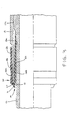
- the second driveshaft section 13 is also generally hollow and cylindrical in shape (although such is not required) and includes a first end having a plurality of axially extending female splines 13a formed or otherwise provided on an inner surface thereof. If desired, the end portions of the female splines 13a adjacent to the first end of the second driveshaft section 13 may be gradually tapered so as to blend smoothly with the inner surface of the second driveshaft section 13 at the first end thereof, as shown in Fig. 3.
- a helical thread 13b or similar structure is formed or otherwise provided on the outer surface of the first end of the second driveshaft section 13. The purpose for this helical thread 13b will be explained below.
- a second end fitting 14 is secured to a second end of the second driveshaft section 13.
- the second end fitting 14 may also, for example, be a conventional tube yoke including a pair of yoke arms and a hollow cylindrical sleeve portion.
- the hollow cylindrical sleeve portion of the second end fitting 14 extends within the second end of the second driveshaft section 13 and can be secured thereto in any conventional manner, such as by welding.
- the yoke arms of the second end fitting 14 are adapted to form a portion of a second universal joint, such as described above.
- the second end of the first driveshaft section 12 is inserted telescopically within the first end of the second driveshaft section 13 to form a slip joint, as shown in Figs. 1 and 3.
- the male splines 12a provided on the second end of the first driveshaft section 12 cooperate with the female splines 13a provided on the first end of the second driveshaft section 13.
- the cooperating male and female splines 12a and 13a permit at least a limited amount of relative axial movement to occur between the first driveshaft section 12 and the second driveshaft section 13.
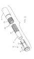
- the driveshaft assembly 10 further includes an annular wedge member, indicated generally at 20, that is adapted to extend between a portion of the outer surface of the first driveshaft section 12 and a portion of the inner surface of the second driveshaft section 13.
- the wedge member 20 is generally hollow and cylindrical in shape (although such is not required) and includes an annular body portion 21 having a plurality of leg portions 22 extending therefrom.
- the body portion 21 of the wedge member 20 has an annular groove 23 or similar structure formed in the outer surface thereof. The purpose for this annular groove 23 will be explained below.
- the leg portions 22 all have the same shape, as best shown in Fig. 2. However, the leg portions 22 of the wedge member 21 may be formed having any desired shape or combination of shapes.
- the illustrated leg portions 22 are gradually tapered as they extend axially outwardly from the body portion 21 from a maximum thickness adjacent to the body portion 21 to a minimum thickness at the ends thereof, as best shown in Fig. 3.
- the leg portions 22 need not be tapered in this manner or at all if desired.
- the wedge member 20 has four of such leg portions 22 extending axially from the body portion 21.
- the wedge member 20 may have any desired number of such leg portions 22.
- the male splines 12a provided on the second end of the first driveshaft section 12 cooperate with the female splines 13a provided on the first end of the second driveshaft section 13 in the manner described above to form the slip joint.
- an annular space is defined between a portion of the outer surface of the first driveshaft section 12 (the portion of the first driveshaft section 12 that is located axially inwardly from the end having the male splines 12a provided thereon) and a portion of the inner surface of the second driveshaft section 13 (the portion of the second driveshaft section 13 wherein the female splines 13a are tapered).
- This annular space is preferably located outside of the region of the cooperating male and female splines 12a and 13a.
- the annular wedge member 20 is adapted to extend within this annular space to minimize or eliminate looseness between the first and second driveshaft sections 12 and 13, and further to adjustably control the amount of force that is required to be exerted in order to effect relative axial movement therebetween.
- the wedge member 20 is initially disposed about the first driveshaft section 12 such that the leg portions 22 thereof are facing toward the region of the cooperating male and female splines 12a and 13a. Then, the wedge member 20 is moved axially along the first driveshaft section 12 such that the leg portions 22 are received within the annular space defined between the outer surface of the first driveshaft section 12 and the inner surface of the second driveshaft section 13, as best shown in Fig. 3. As a result, the tapered leg portions 22 of the wedge member 20 engage the outer surface of the first driveshaft section 12 and the inner surfaces of the female splines 13a of the second driveshaft section 13.
- the wedge member 20 occupies the annular space therebetween so as to minimize or eliminate looseness between the first and second driveshaft sections 12 and 13. Also, by adjusting the position of the wedge member 20 relative to the first and second driveshaft sections 12 and 13, the magnitude of the frictional engagement between these three components can be varied. Consequently, the amount of force that is required to be exerted in order to effect relative axial movement between the first and second driveshaft sections 12 and 13 can be adjustably controlled.
- a cap is provided for facilitating the positioning of the wedge member 20 relative to the first and second driveshaft sections 12 and 13 and for retaining the wedge member 20 in a desired relative position.
- the illustrated cap 25 includes a body portion 26 that is generally hollow and cylindrical in shape and a radially inwardly extending lip portion 27. If desired, an annular recessed area 26a may be formed or otherwise provided in the outer surface of the body portion 26 of the cap 25.
- the recessed area 26a can be used to facilitate the connection of one end of a conventional flexible boot (not shown) or similar sealing structure to prevent dirt, water, and other contaminants from entering into the region of the cooperating male and female splines 12a and 13a. The other end of the flexible boot would be supported on the outer surface of the first driveshaft section 12 in a conventional manner.
- the inner surface of the body portion 26 of the cap 25 has a helical thread 26b or similar structure formed or otherwise provided thereon.
- the helical thread 26b of the cap 25 cooperates with the helical thread 13b that is provided on the outer surface of the first end of the second driveshaft section 13.
- rotational movement of the cap 25 relative to the second driveshaft section 13 simultaneously causes the cap 25 to move axially relative to the second driveshaft section 13.
- the direction of such axial movement will depend upon the direction of the rotation of the cap 25 relative to the second driveshaft section 13.
- the lip portion 27 of the cap 25 is adapted to extend within the groove 23 formed in the outer surface of the body portion 21 of the wedge member 20.
- rotational movement of the cap 25 causes the wedge member 20 to be moved axially relative to the first and second driveshaft sections 12 and 13, for the purposes discussed above.
- the rotational movement of the cap 25 can be effected in any desired manner, such as by hand or with the use of a tool.
Landscapes
- Engineering & Computer Science (AREA)
- General Engineering & Computer Science (AREA)
- Ocean & Marine Engineering (AREA)
- Mechanical Engineering (AREA)
- Shafts, Cranks, Connecting Bars, And Related Bearings (AREA)
Applications Claiming Priority (2)
| Application Number | Priority Date | Filing Date | Title |
|---|---|---|---|
| US403828 | 1982-07-30 | ||
| US10/403,828 US7044860B2 (en) | 2003-03-31 | 2003-03-31 | Slip joint for vehicle driveshaft assembly |
Publications (2)
| Publication Number | Publication Date |
|---|---|
| EP1464854A2 true EP1464854A2 (de) | 2004-10-06 |
| EP1464854A3 EP1464854A3 (de) | 2007-04-04 |
Family
ID=32850578
Family Applications (1)
| Application Number | Title | Priority Date | Filing Date |
|---|---|---|---|
| EP04251894A Withdrawn EP1464854A3 (de) | 2003-03-31 | 2004-03-30 | Teleskopische Antriebswellekupplung für Kraftfahrzeug |
Country Status (2)
| Country | Link |
|---|---|
| US (1) | US7044860B2 (de) |
| EP (1) | EP1464854A3 (de) |
Cited By (2)
| Publication number | Priority date | Publication date | Assignee | Title |
|---|---|---|---|---|
| EP2840265A3 (de) * | 2013-08-23 | 2015-06-24 | Steering Solutions IP Holding Corporation | Sicherungskappe für Wellenanordnung |
| WO2017148481A1 (en) * | 2016-03-01 | 2017-09-08 | Vestas Wind Systems A/S | A wind turbine comprising a torque transmitting coupling |
Families Citing this family (10)
| Publication number | Priority date | Publication date | Assignee | Title |
|---|---|---|---|---|
| JP2005344743A (ja) * | 2004-05-31 | 2005-12-15 | Toyota Motor Corp | ベルト式無段変速機 |
| US20060046858A1 (en) * | 2004-08-26 | 2006-03-02 | Ronald Brissette | Driveshaft assembly with torque ring coupling |
| US20090215543A1 (en) * | 2008-02-25 | 2009-08-27 | American Axle & Manufacturing, Inc. | Slip yoke with internal splines having permanent coating and related method |
| US8262491B2 (en) | 2008-07-25 | 2012-09-11 | GKN Driveline Newton, LLC | Driveshaft assembly and method for assembling driveshaft assembly |
| US20180071476A1 (en) * | 2014-11-19 | 2018-03-15 | Koninklijke Philips N.V. | Frame/headgear adjustment assembly |
| EP3025846B1 (de) * | 2014-11-28 | 2019-11-13 | Crompton Technology Group Limited | Zusammengesetzter Zug-/Druckstab |
| US9845861B1 (en) * | 2016-05-26 | 2017-12-19 | GM Global Technology Operations LLC | Rotatable assembly including a coupling interface |
| DE102016215869A1 (de) * | 2016-08-24 | 2018-03-01 | Thyssenkrupp Ag | Längenveränderbare Lenkwelle und Verfahren zur Herstellung einer längenveränderbaren Lenkwelle |
| KR20210101007A (ko) * | 2020-02-07 | 2021-08-18 | 이래에이엠에스 주식회사 | 볼 스플라인 구조를 갖는 드라이브 샤프트용 관형 샤프트의 제조 방법 및 그에 의해 제조된 관형 샤프트 |
| EP3922415B1 (de) * | 2020-06-10 | 2024-04-10 | Tangshan Changzhi Agricultural Tools Design Manufacturing Co., Ltd. | Werkzeugleiste |
Family Cites Families (25)
| Publication number | Priority date | Publication date | Assignee | Title |
|---|---|---|---|---|
| US2158757A (en) * | 1938-07-11 | 1939-05-16 | William J Katzberg | Coupling |
| US4000919A (en) * | 1969-04-09 | 1977-01-04 | Edwards Francis P | Pipe coupler |
| US3697102A (en) * | 1970-12-09 | 1972-10-10 | Jay F Falke | Tubing coupling |
| US4022499A (en) * | 1975-04-14 | 1977-05-10 | Aeroquip Corporation | Tube retaining compression fitting |
| US4059297A (en) * | 1976-03-08 | 1977-11-22 | Parker-Hannifin Corporation | Tube coupling |
| US4082326A (en) * | 1976-08-30 | 1978-04-04 | Canadian Brass Limited | Compressible member for use in compression joint pipe connector |
| DE2747319C2 (de) * | 1977-10-21 | 1979-11-22 | Gelenkwellenbau Gmbh, 4300 Essen | Gelenkwelle bestehend aus zwei Kreuzgelenken |
| US4346923A (en) * | 1979-08-23 | 1982-08-31 | Vaponics Inc. | Apparatus for joining tubing |
| EP0047107B1 (de) * | 1980-08-29 | 1984-07-11 | Brd Company Limited | Keilwellenverbindung |
| US4624483A (en) * | 1981-08-26 | 1986-11-25 | Halliburton Company | Quick connect coupler |
| US4531766A (en) * | 1981-08-31 | 1985-07-30 | Crase Gary M | Releasable couplings for drill strings |
| US4445714A (en) * | 1982-03-25 | 1984-05-01 | Dresser Industries, Inc. | Compression end pipe coupling for plastic pipe |
| AT384405B (de) * | 1985-07-22 | 1987-11-10 | Supervis Ets | Laengenveraenderbare lenkspindel fuer lenkvorrichtungen bei kraftfahrzeugen |
| US4693316A (en) * | 1985-11-20 | 1987-09-15 | Halliburton Company | Round mandrel slip joint |
| US4655486A (en) * | 1986-02-07 | 1987-04-07 | Price Pfister, Inc. | Water faucet inlet line connector |
| US5207459A (en) * | 1991-07-11 | 1993-05-04 | Dresser Industries, Inc. | Transition coupling for pipes |
| US5344195A (en) * | 1992-07-29 | 1994-09-06 | General Electric Company | Biased fluid coupling |
| US5460574A (en) * | 1993-08-31 | 1995-10-24 | Trw Inc. | Variable length shaft assembly with a lash bushing |
| US5433551A (en) * | 1994-01-12 | 1995-07-18 | Gordon; Larry D. | Telescoping rod assembly |
| JP3341961B2 (ja) * | 1994-02-28 | 2002-11-05 | 株式会社ユニシアジェックス | 軸継手構造 |
| US5466019A (en) * | 1994-09-26 | 1995-11-14 | Komolrochanaporn; Naris | Pipe coupling |
| US5918913A (en) * | 1997-10-30 | 1999-07-06 | Dana Corporation | Quick-connect coupling for articulating hose lines |
| EP1045183A4 (de) * | 1997-12-24 | 2004-03-31 | Mikuni Plastics Co Ltd | Rohr aus hartem thermoplastischem harz, rohrkupplungsstruktur sowie herstellungsverfahren |
| FR2795785B1 (fr) * | 1999-06-30 | 2002-06-28 | Nacam | Dispositif d'accouplement a billes de deux arbres coulissants |
| US6620050B2 (en) * | 2001-10-30 | 2003-09-16 | Mando Corporation | Universal joint |
-
2003
- 2003-03-31 US US10/403,828 patent/US7044860B2/en not_active Expired - Fee Related
-
2004
- 2004-03-30 EP EP04251894A patent/EP1464854A3/de not_active Withdrawn
Cited By (3)
| Publication number | Priority date | Publication date | Assignee | Title |
|---|---|---|---|---|
| EP2840265A3 (de) * | 2013-08-23 | 2015-06-24 | Steering Solutions IP Holding Corporation | Sicherungskappe für Wellenanordnung |
| US9347492B2 (en) | 2013-08-23 | 2016-05-24 | Steering Solutions Ip Holding Corporation | Retainer cap for shaft assembly |
| WO2017148481A1 (en) * | 2016-03-01 | 2017-09-08 | Vestas Wind Systems A/S | A wind turbine comprising a torque transmitting coupling |
Also Published As
| Publication number | Publication date |
|---|---|
| US7044860B2 (en) | 2006-05-16 |
| EP1464854A3 (de) | 2007-04-04 |
| US20040192449A1 (en) | 2004-09-30 |
Similar Documents
| Publication | Publication Date | Title |
|---|---|---|
| US6582151B2 (en) | Driving axle assembly | |
| US7029398B1 (en) | Flange yoke and companion flange supported on a splined shaft | |
| US5807180A (en) | Constant velocity universal joint shaft and inner race combination | |
| JPH0539814A (ja) | 伸縮自在な継手 | |
| EP1559920A1 (de) | Befestigungsvorrichtung mit gegensinnigen Gewindeabschnitten zum Fixieren von zwei Komponenten aneinander | |
| US7044860B2 (en) | Slip joint for vehicle driveshaft assembly | |
| EP1479933A2 (de) | Teleskopische Kupplung mit Kugeln und spiralförmigen Käfig | |
| JP2010529373A (ja) | 伝動装置のジャーナルを駆動軸の駆動継手の継手本体に相対回動不能に結合するための装置 | |
| US20050277480A1 (en) | Flange assembly for supporting a bearing and an end fitting in a driveshaft assembly | |
| EP1473477A2 (de) | Verfahren zur Herstellung der Nuten einer Rohrdichtung in einer Fahrzeugantriebswellenvorrichtung | |
| EP1477696A2 (de) | Abgedichtete axialverschiebbare Rohrverbindung | |
| US6364778B1 (en) | Axially adjustable steering shaft assembly with ball spline | |
| CN100520098C (zh) | 具有等速接头的组合式驱动轴组件 | |
| US20060130306A1 (en) | Method of manufacturing a sliding spline type of slip joint | |
| US20060130309A1 (en) | Method of manufacturing a splined member having a coating of a material applied thereto | |
| US6158916A (en) | Universal joint connector | |
| US7052398B2 (en) | Pressure regulator assembly for use with a slip joint in a driveshaft assembly | |
| US20080305878A1 (en) | Constant velocity joint | |
| US20090029783A1 (en) | Axially adjustable driveshaft assembly and method of installing same | |
| EP1286067B1 (de) | Druckregelungsanordnung für teleskopische Antriebswelle | |
| US20010014624A1 (en) | Telescopic mechanical transmission with angular adjustment for assembly | |
| US7726000B2 (en) | Method of securing first and second splined members together | |
| US20100029397A1 (en) | Slip joint for use in a drive train system | |
| US10047800B2 (en) | Driveshaft with single constant-velocity joint and locking mechanism | |
| JP2026019580A (ja) | トルク伝達装置及び等速自在継手 |
Legal Events
| Date | Code | Title | Description |
|---|---|---|---|
| PUAI | Public reference made under article 153(3) epc to a published international application that has entered the european phase |
Free format text: ORIGINAL CODE: 0009012 |
|
| AK | Designated contracting states |
Kind code of ref document: A2 Designated state(s): AT BE BG CH CY CZ DE DK EE ES FI FR GB GR HU IE IT LI LU MC NL PL PT RO SE SI SK TR |
|
| AX | Request for extension of the european patent |
Extension state: AL LT LV MK |
|
| PUAL | Search report despatched |
Free format text: ORIGINAL CODE: 0009013 |
|
| AK | Designated contracting states |
Kind code of ref document: A3 Designated state(s): AT BE BG CH CY CZ DE DK EE ES FI FR GB GR HU IE IT LI LU MC NL PL PT RO SE SI SK TR |
|
| AX | Request for extension of the european patent |
Extension state: AL LT LV MK |
|
| AKX | Designation fees paid | ||
| REG | Reference to a national code |
Ref country code: DE Ref legal event code: 8566 |
|
| STAA | Information on the status of an ep patent application or granted ep patent |
Free format text: STATUS: THE APPLICATION IS DEEMED TO BE WITHDRAWN |
|
| 18D | Application deemed to be withdrawn |
Effective date: 20071005 |