EP1464862B1 - Dispositif central de débrayage pour un embrayage hydraulique - Google Patents
Dispositif central de débrayage pour un embrayage hydraulique Download PDFInfo
- Publication number
- EP1464862B1 EP1464862B1 EP04006180A EP04006180A EP1464862B1 EP 1464862 B1 EP1464862 B1 EP 1464862B1 EP 04006180 A EP04006180 A EP 04006180A EP 04006180 A EP04006180 A EP 04006180A EP 1464862 B1 EP1464862 B1 EP 1464862B1
- Authority
- EP
- European Patent Office
- Prior art keywords
- guide sleeve
- cylinder housing
- annular
- annular flange
- insert
- Prior art date
- Legal status (The legal status is an assumption and is not a legal conclusion. Google has not performed a legal analysis and makes no representation as to the accuracy of the status listed.)
- Expired - Lifetime
Links
- 229920003023 plastic Polymers 0.000 claims description 10
- 239000004033 plastic Substances 0.000 claims description 10
- 230000000295 complement effect Effects 0.000 claims description 8
- 238000007789 sealing Methods 0.000 claims description 4
- 238000002604 ultrasonography Methods 0.000 claims description 4
- 230000000694 effects Effects 0.000 claims 1
- 230000002093 peripheral effect Effects 0.000 description 13
- 230000005540 biological transmission Effects 0.000 description 10
- 238000003466 welding Methods 0.000 description 9
- 238000005304 joining Methods 0.000 description 8
- 238000004519 manufacturing process Methods 0.000 description 6
- 238000000034 method Methods 0.000 description 6
- 230000008901 benefit Effects 0.000 description 5
- 239000002184 metal Substances 0.000 description 5
- 230000008569 process Effects 0.000 description 5
- 230000004323 axial length Effects 0.000 description 4
- 229910000831 Steel Inorganic materials 0.000 description 3
- 230000009471 action Effects 0.000 description 3
- 238000013461 design Methods 0.000 description 3
- 239000010959 steel Substances 0.000 description 3
- 230000007704 transition Effects 0.000 description 3
- 230000015572 biosynthetic process Effects 0.000 description 2
- 238000010276 construction Methods 0.000 description 2
- 238000006073 displacement reaction Methods 0.000 description 2
- 239000012530 fluid Substances 0.000 description 2
- 238000003780 insertion Methods 0.000 description 2
- 230000037431 insertion Effects 0.000 description 2
- 239000000463 material Substances 0.000 description 2
- 230000007246 mechanism Effects 0.000 description 2
- 230000036316 preload Effects 0.000 description 2
- 238000011144 upstream manufacturing Methods 0.000 description 2
- 239000000853 adhesive Substances 0.000 description 1
- 230000001070 adhesive effect Effects 0.000 description 1
- 230000008859 change Effects 0.000 description 1
- 238000005352 clarification Methods 0.000 description 1
- 150000001875 compounds Chemical class 0.000 description 1
- 230000006835 compression Effects 0.000 description 1
- 238000007906 compression Methods 0.000 description 1
- 238000005520 cutting process Methods 0.000 description 1
- 230000000881 depressing effect Effects 0.000 description 1
- 238000011161 development Methods 0.000 description 1
- 230000018109 developmental process Effects 0.000 description 1
- 238000005516 engineering process Methods 0.000 description 1
- 238000002347 injection Methods 0.000 description 1
- 239000007924 injection Substances 0.000 description 1
- 239000007788 liquid Substances 0.000 description 1
- 238000012545 processing Methods 0.000 description 1
- 238000004080 punching Methods 0.000 description 1
- 239000007787 solid Substances 0.000 description 1
- 230000003068 static effect Effects 0.000 description 1
- 238000012360 testing method Methods 0.000 description 1
Images
Classifications
-
- F—MECHANICAL ENGINEERING; LIGHTING; HEATING; WEAPONS; BLASTING
- F16—ENGINEERING ELEMENTS AND UNITS; GENERAL MEASURES FOR PRODUCING AND MAINTAINING EFFECTIVE FUNCTIONING OF MACHINES OR INSTALLATIONS; THERMAL INSULATION IN GENERAL
- F16D—COUPLINGS FOR TRANSMITTING ROTATION; CLUTCHES; BRAKES
- F16D25/00—Fluid-actuated clutches
- F16D25/08—Fluid-actuated clutches with fluid-actuated member not rotating with a clutching member
- F16D25/082—Fluid-actuated clutches with fluid-actuated member not rotating with a clutching member the line of action of the fluid-actuated members co-inciding with the axis of rotation
- F16D25/083—Actuators therefor
Definitions
- the present invention relates to a Monausschreiber for a hydraulic clutch actuator according to the preamble of claim 1. More particularly, the invention relates to a Monausschreiber a hydraulic clutch actuator for a motor vehicle friction clutch, as they are used in masses in the automotive industry.
- a conventional hydraulic clutch actuator for motor vehicles has a master cylinder connected to a reservoir filled with hydraulic fluid, e.g. can be operated via a clutch pedal.
- the master cylinder is hydraulically connected via a pressure line with a slave cylinder, so that the pressure generated by depressing the clutch pedal in the master cylinder via the liquid column in the pressure line to the slave cylinder is transferable.
- the release bearing of the friction clutch is acted upon by the slave cylinder with an actuating force to disconnect via a release mechanism, the clutch pressure plate from the Kupplungsmit kindergartenusion and thus the engine from the transmission of the motor vehicle.
- the slave cylinder In order to ensure a uniform actuation of the friction clutch with the smallest possible space requirement of the slave cylinder, it has been proposed in the prior art to form the slave cylinder as a ring cylinder, which is arranged around the clutch or transmission shaft around and preferably attached to the transmission housing.
- an annular piston in the axial direction of the clutch or transmission shaft is slidably disposed, which is in operative connection with the release bearing of the friction clutch.
- the guide sleeve end has an annular flange which has an end face remote from the annular piston and a radially outer circumferential surface and over which the guide sleeve is attached to an end face of the cylinder housing.
- the cylinder housing Concentric with the annular groove, the cylinder housing is provided with an incision, the length of which exceeds the annular groove and the radial deflection of the undercut forming snap-action nose of the cylinder housing during insertion of the axial portion of the Ringflansches only in the annular groove of the cylinder housing allows.
- a disadvantage of this state of the art is in addition to the elaborate design of the annular flange of the guide sleeve (axial section with end workedem board) and the cylinder housing with respect to the connection of the guide sleeve (annular groove with an undercut and concentric incision to see it) in that the formation of the snap connection with the axial portion and the board on the annular flange of the guide sleeve on the one hand and the undercut and the recess on the cylinder housing on the other hand, in particular, a relatively large axial length of the Gottaus Kohlers conditional.
- the axial space for the Gottausschreiber is in the drive train of the motor vehicle, in which the friction clutch, the Gottausschreiber and the gearbox are arranged in series one behind the other, but very narrow. To make matters worse here is that variant constructions are common in which different performance friction clutches are housed in the same clutch housing, which may not be hindered by the Monausschreiber.
- the invention therefore has the object to provide a simple as possible Primaausscher for a hydraulic clutch actuation, which has the smallest possible axial length.
- a guide sleeve end has an annular flange with an end face remote from the annular piston and a radially outer surface over which the guide sleeve is attached to a front side of the cylinder housing, the annular flange adjacent a Merhhoff of in the Seen overhead Kreisring Wunschförmigen, emanating from the end axial grooves in the cylinder housing formed, in each of which a substantially complementary shaped insert is firmly inserted, which engages behind the annular flange only on the lateral surface thereof to secure the guide sleeve on the cylinder
- annular flange of the guide sleeve in the inventive fastening of the guide sleeve on the cylinder housing plane can be executed, a complicated design of the annular flange in the axial direction of the Guide sleeve as in the generic state of the art is therefore unnecessary. Also recesses, holes, punching etc. in the annular flange of the guide sleeve, which are partially necessary in the prior art ( DE 199 23 853 A1 .
- a plurality of annular grooves formed in plan view is formed, in each of which a substantially complementary shaped, i. likewise circular ring-shaped insert part is used.
- a substantially complementary shaped, i. likewise circular ring-shaped insert part is used.
- Such a non-annular closed configuration of the insert allows the axial groove and insert to be less tightly tolerated to fit together. Any geometrical deviations at the axial groove or insert part can possibly be compensated for by the greater elasticity of the circular-ring-shaped insert part compared to an annular formation of the insert part.
- the cylinder housing material present in the circumferential direction between the annular axial grooves increases advantageously the rigidity of the cylinder housing.
- the insert may be inserted into the axial groove by means of a suitable adhesive be glued.
- the cylinder housing and the insert parts are made of ultrasonically weldable plastics and the inserts are ultrasonically welded to the cylinder housing.
- An ultrasonic welding process is particularly suitable for cost-effective automated assembly of inserts in mass production.
- Plastic as a material for cylinder housing and insert also brings about weight advantages compared to a metallic design in addition to processing advantages.
- the insert parts may be provided on their inner side facing away from the guide sleeve and its outer side facing away from the guide sleeve, each with a step which is welded to the joining of the respective insert in the associated axial groove of the cylinder housing under the action of ultrasound with an adjacent edge of the associated axial groove.
- a welding of the insert part with the cylinder housing could also take place only on one side of the insert part, in particular its inside facing the guide sleeve
- a double-sided welding of the insert part with the Axialnutflanken of the cylinder housing has the advantage over the insert that no moments on the Versch dieungsstellen can be transmitted.
- the insert part can be pre-positioned over its section upstream of the stages before ultrasonic welding to the axial groove of the cylinder housing. This, too, is conducive to problem-free automated assembly of the insert part in mass production.
- the step on the inside of the respective insert part and the step on the outside of the respective insert part in the joining direction of the respective insert part are matched in terms of position and length to one another such that the steps coincide and substantially over the same length with the adjacent flanks the associated axial groove are welded, it can during the Ultrasonic welding does not lead to an undesirable tilting of the insert part with respect to the axial groove. Also, the time required for the ultrasonic welding process is minimized.
- the axial grooves in the cylinder housing may have a substantially rectangular groove cross-section, which simplifies the production of the cylinder housing and the insert part, in particular if they are injection-molded from plastic.
- a positive connection wherein at the respective insert part a retaining lug is formed with a slope which engages behind a complementary shaped, circumferential bevel on the annular flange, which extends from the end face of the annular flange on the lateral surface thereof.
- a positive connection wherein at the respective insert part a retaining lug is formed with a slope which engages behind a complementary shaped, circumferential bevel on the annular flange, which extends from the end face of the annular flange on the lateral surface thereof.
- any tolerances can be compensated for or between the components involved in a simple manner.
- the slope on the lateral surface of the annular flange can, if the guide sleeve is deep-drawn from a sheet steel, also easily be formed when cutting the guide sleeve from the deep drawing with, the annular flange is solidified by forming in the region of the slope at the same time advantageous.
- An embodiment of the Monausgurers in which in the cylinder housing, starting from the end face of a recess for receiving the annular flange is formed whose depth is equal to or smaller than the thickness of the annular flange, is also a short length of the Monausgurers conducive. Nevertheless, in the mounted on the gear housing state of the central release the guide sleeve over the annular flange defined supported on the transmission housing, which, among other things, leaks between the guide sleeve and cylinder housing are reliably avoided.
- a ring member is provided, which is arranged at the end facing away from the annular piston end of the pressure chamber between the guide sleeve and the cylinder wall and the guide sleeve centered with respect to the cylinder wall.
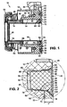
- Fig. 1 is a Monausschreiber 10 for a hydraulic clutch actuation for dry friction clutches in the unassembled state shown in basic position.
- the Monausschreiber 10 has an existing plastic cylinder housing 12 with a cylinder wall 14 and a concentrically disposed within the cylinder wall 14 guide sleeve 16 which is deep drawn from a steel sheet.
- guide sleeve 16 with thenreibkupplung (not shown) operatively connected annular piston 18 made of plastic displaceable, which can be acted upon by one of the cylinder wall 14 and the guide sleeve 16, more precisely its outer peripheral surface pressure chamber 20 with a pressure medium to the dry friction by Displacement of the annular piston 18 disengage.
- the guide sleeve 16 has end, ie at its in Fig. 1 right end of a plane annular flange 22, the one facing away from the annular piston 18 end face 24 and a radially outer surface 26 has. About the annular flange 22, the guide sleeve 16 is attached to an end face 28 of the cylinder housing 12.
- annular flange 22 adjacent to a plurality of, in the illustrated embodiment, two substantially with respect to the central axis of the guide sleeve 16 substantially diametrically opposite, emanating from the end face 28 Axialnuten 30 are formed in the cylinder housing 12, in each of which a substantially complementary shaped insert 32 is fixedly inserted, which engages behind the annular flange 22 on the lateral surface 26 to secure the guide sleeve 16 on the cylinder housing 12.
- an upper side 34 of each insert part 32 facing away from the annular piston 18 lies at least in a plane defined by the end face 24 of the annular flange 22 of the guide sleeve 16 or, viewed from the annular piston 18, before this, as in FIG Fig. 2 shown, whereby this mounting arrangement builds only very short in the axial direction of the Monausgurers 10.
- the cylinder housing 12 has a discharge nozzle 36 extending from its outer circumference, through which a pressure medium channel (not shown) extends, which opens into the pressure chamber 20 at a location not shown here.
- a pressure line (not shown) are connected, so that the pressure medium, namely hydraulic fluid can be supplied to the pressure chamber 20 via the pressure medium channel.
- the cylinder housing 12 in the illustrated embodiment, two concentrically arranged, substantially hollow cylindrical wall sections 38, 40, which at one, ie in Fig. 1 right end are connected to each other via a flange portion 42.
- the flange portion 42 is provided on the outer peripheral side with a plurality of angularly spaced fastening eyes (not shown), which in the motor vehicle in a known manner the Attachment of the central release 10 on a transmission wall or a gear cover (not shown) by means of screws (not shown) are used, which pass through the fastening eyes and pull the Monausschreiber 10 with the end face 28 of the cylinder housing 12 against the transmission wall or the gear cover.
- the cylinder housing 12 with the adjoining the flange 42 pressure port 36, its Wandungsablveslieen 38, 40 and connecting them, the fastening eyes having flange portion 42 is preferably injection molded in one piece of plastic.
- the cylindrical inner peripheral surface of the radially inner wall portion 38 of the cylinder housing 12 forms the cylinder wall 14, while the outer peripheral surface of the Wandungsabitess 38 together with the inner peripheral surface of the opposite axially slightly longer, radially outer wall portion 40 of the cylinder housing 12 defines an annular space 44.
- the annular space 44 is to the left in Fig. 1 open and ends on the in Fig. 1 right side on the flange portion 42 of the cylinder housing 12th
- the annular space 44 serves to receive a preload spring 46, in the illustrated embodiment, a helical compression spring which is located at its in Fig. 1 right end in an annular groove 48 on the flange portion 42 of the cylinder housing 12 is supported and on its in Fig. 1 left side over a deep-drawn from a metal sheet spring plate 50 a defined biasing force on a known release bearing 52 applies.
- the release bearing 52 is by means of a sheet metal part 54 at in Fig. 1 attached left end of the annular piston 18 in a suitable manner, so that the release bearing 52 in pressurizing the annular pressure chamber 20 in the axial, ie in Fig. 1 Horizontal direction is displaced to the dry friction clutch in a conventional manner off or engage.
- a preload spring 46 in the illustrated embodiment, a helical compression spring which is located at its in Fig. 1 right end in an annular groove 48 on the flange portion 42 of the cylinder housing 12 is supported and on its in Fig. 1 left side over a deep-
- a dynamic seal in the form of an elastomeric sealing sleeve 58 is suitably attached.
- the sealing collar 58 shown here in the undeformed state for ease of illustration is close to both the cylinder wall 14 of the cylinder housing 12 and on the outer peripheral surface of the guide sleeve 16 to the pressure chamber 20 to the left in Fig. 1 seal.
- the ring member 60 On the side facing away from the annular piston 18, ie in Fig. 1 right end of the pressure chamber 20 is inserted between the guide sleeve 16, more precisely the outer peripheral surface and the cylinder wall 14 of the cylinder housing 12, preferably made of a plastic injection-molded ring member 60 which centers the guide sleeve 16 with respect to the cylinder wall 14.
- the ring member 60 has a substantially L-shaped cross-section whose shorter leg rests against the outer peripheral surface of the guide sleeve 16, while the longer leg rests against the ring piston 18 facing annular surface 62 of the annular flange 22 of the guide sleeve 16. With its outer peripheral surface, the ring member 60 is finally against the cylinder housing 12.
- a static seal arrangement is further provided, which the pressure chamber 20 to the right in Fig. 1 seals against the environment.
- the seal assembly has in the illustrated embodiment, two elastomeric O-rings 64, 66, of which an O-ring 66 in a on the outer circumference the ring member 60 formed annular groove 68 is received to seal between the ring member 60 and the cylinder housing 12.
- the other O-ring 64 seals between the ring member 60 and the guide sleeve 16, for which purpose it is inserted between a chamfer 70 of the ring member 60 on the one hand and a transition section 72 of the guide sleeve 16 between the sleeve portion and the annular flange 22 on the other.
- Fig. 1 Finally, it can be seen that in the cylinder housing 12, starting from the end face 28 in a plan view from the right in Fig. 1 seen circular depression or recess 74 is formed, which serves to receive the annular flange 22 of the guide sleeve 16.
- the recess 74 has an in relation to a defined by the end face 28 of the cylinder housing 12 level Fig. 2 drawn depth t, which is equal to or - as in the illustrated embodiment - smaller than that in Fig. 1 drawn thickness d of the annular flange 22 of the guide sleeve 16 is, so that the annular flange 22 of the guide sleeve 16 protrudes slightly with its end face 24 on the end face 28 of the cylinder housing 12.
- Fig. 2 are in a versus the Fig. 1 enlarged scale details of the attachment of the guide sleeve 16 to the cylinder housing 12 to recognize.
- the cylinder housing 12 and the two of the attachment of the guide sleeve 16 on the cylinder housing 12 serving inserts 32 made of ultrasonic weldable plastics, and in the assembled state of the central release 10 each insert 32 with the cylinder housing 12 in the respectively associated Axialnut 30 is actually ultrasonically welded.
- the cylinder housing 12 and the insert member 32 drawn in the non-ultrasonic welded state one above the other, wherein the position of the indicated insert member 32 corresponds to the position of an ultrasonically welded to the cylinder housing 12 insert part 32 substantially.
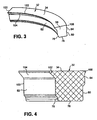
- two axial grooves 30 which extend from the end face 28 of the cylinder housing 12 are formed in the cylinder housing 12 in a substantially diametrically opposite arrangement relative to the center axis of the guide sleeve 16. Seen in the radial direction are the axial grooves 30, which according to Fig. 2 have a substantially rectangular groove cross-section, at the edge of the recess 74 in the cylinder housing 12. In a plan view from the right in the Fig. 1 and 2 considered each axial groove 30 has the shape of a circular ring piece. In the axial grooves 30, an insert member 32 is fixedly inserted, which has a shape of the axial groove 30 is substantially complementary shape, as the 3 and 4 illustrate.
- the one according to the Fig. 2 and 4 planar bottom 76 having insert 32 is, in particular the Fig. 2 shows, on its the guide sleeve 16 facing inside 78 and its remote from the guide sleeve 16 outside 80, each with a step 82, 84 is provided.
- the steps 82, 84 are weldable when joining the insert 32 into the associated axial groove 30 of the cylinder housing 12 under the action of ultrasound with an adjacent flank 86 and 88 of the axial groove 30, to which the stages 82, 84 with respect to the radial dimensions of the axial groove 30 a certain excess to have.
- the step 82 on the inside 78 of the insert 32 and the step 84 on the outside 80 of the insert 32 in the joining direction of the insert 32 ie in the horizontal direction in Fig. 2 seen regarding Position and length coordinated so that the steps 82, 84 at the same time and - like the overlapping areas of cylinder housing 12 and insert 32 in Fig. 2 make it clear - are essentially over the same length with the adjacent flanks 86 and 88 of the axial groove 30 welded.
- the axial groove 30 is provided on both the inner peripheral and outer peripheral sides, each with a rectangular cross-section recess 90 and 92, which forms an edge 94 and 96 in the axial groove 30.
- the dimensions 90, 92 which are matched with respect to their dimensions on the steps 82, 84 serve to pre-center the insert 32 at its steps 82, 84 during the joining of the insert 32 into the associated axial groove 30.
- the insert part 32 which has a curvature corresponding to the annular flange 22 of the guide sleeve 16 and not necessarily be formed as a solid body, but also could have a honeycomb profile
- the outer peripheral side has a triangular in cross-section stop lug 108, which adjoins the top 34 and the step 84 of the insert 32 connects.
- the stop lug 108 may abut when joining the insert part 32 in the associated axial groove 30 on a formed on the axial groove 30 draft 110.
- the guide sleeve 16 When assembling the central release 10, the guide sleeve 16 is first pushed into the cylinder housing 12 to fasten the guide sleeve 16 on the cylinder housing 12 until the annular flange 22 of the guide sleeve 16 comes with its annular surface 62 in the recess 74 of the cylinder housing 12 to the cylinder housing 12 to the plant. In this case, the guide sleeve 16 is centered with respect to the cylinder wall 14 of the cylinder housing 12 by means of the ring member 60. Next, the two insert members 32 are slid into the axial grooves 30 of the cylinder housing 12 until the steps 82, 84 of the respective insert member 32 abut against the edges 94, 96, respectively, in the associated axial groove 30.
- each insert member 32 is acted upon by its upper side 34 with a force and is pushed continuously under the action of ultrasound by a known per se ultrasonic welding device in the associated axial groove 30 into it.
- the steps 82 of the insert parts 32 merge with the radially inner flanks 86 of the axial grooves 30, while the steps 84 of the insert parts 32 merge with the radially outer flanks 88 of the axial grooves 30.
- the positive connection achieved in any case is sufficiently resilient to perform at the Gottausschreiber 10 a conventional pneumatic leak test and to transport the Monausschreiber 10 without problems.
- the positive engagement achieved in the vehicle mounted state of the Monausschreibers 10 is still supported by the fact that the annular flange 22 of the guide sleeve 16 is clamped between the transmission wall and the gear cover on one side and the cylinder housing 12 on the other side.
- a plurality of outgoing from the end axial grooves in the cylinder housing is formed, in each of which an insert is firmly inserted, which engages behind the annular flange on the lateral surface, wherein a side facing away from the annular piston top of the insert in a plane defined by the end face of the annular flange or, seen from the ring piston, lies in front of this.
Landscapes
- Engineering & Computer Science (AREA)
- General Engineering & Computer Science (AREA)
- Mechanical Engineering (AREA)
- Hydraulic Clutches, Magnetic Clutches, Fluid Clutches, And Fluid Joints (AREA)
Claims (9)
- Dispositif central de débrayage (10) pour un système d'actionnement hydraulique d'embrayage, comprenant un carter de cylindre (12), qui présente une paroi de cylindre (14), et une douille de guidage (16) agencée de manière concentrique à l'intérieur de la paroi de cylindre (14) et sur laquelle est guidé de manière coulissante, un piston annulaire (18) qui peut être amené à interagir avec l'embrayage, et peut être sollicité sélectivement par un fluide de pression moyennant une chambre de pression (20) délimitée par la paroi de cylindre (14) et la douille de guidage (16), en vue de débrayer l'embrayage, la douille de guidage (16) comportant, à l'extrémité, un flasque annulaire (22) qui présente une surface frontale (24) dirigée vers l'opposé de là où se trouve le piston annulaire (18) et une surface enveloppe périphérique (26) radialement extérieure, et par l'intermédiaire duquel la douille de guidage (16) est fixée à une face frontale (28) du carter de cylindre (12),
caractérisé en ce qu'au voisinage du flasque annulaire (22), dans le carter de cylindre (12), sont réalisées une pluralité de rainures axiales (30) issues de la face frontale (28) et présentant une forme de secteur annulaire circulaire dans une vue en plan sur la face frontale, et en ce que dans chacune de ces rainures est rapportée, de manière fixe, une pièce d'insert (32) de forme sensiblement complémentaire, qui ne vient surmonter en contre-dépouille le flasque annulaire (22) qu'au niveau de sa surface enveloppe périphérique (26), en vue de fixer la douille de guidage (16) au carter de cylindre (12), un côté externe (34) de la pièce d'insert (32), qui est dirigé vers l'opposé de là où se trouve le piston annulaire (18), se situant dans un plan défini par la surface frontale (24) du flasque annulaire (22), ou bien au-devant ce plan vu à partir du piston annulaire (18). - Dispositif central de débrayage (10) selon la revendication 1, caractérisé en ce que le carter de cylindre (12) et les pièces d'insert (32) sont réalisés en matières plastiques susceptibles d'être soudées par ultrasons, et les pièces d'insert (32) sont soudées par ultrasons au carter de cylindre (12).
- Dispositif central de débrayage (10) selon la revendication 2, caractérisé en ce que les pièces d'insert (32) sont munies respectivement, sur leur côté intérieur (78) dirigé vers la douille de guidage (16) et leur côté extérieur (80) dirigé vers l'opposé de là où se trouve la douille de guidage (16), d'un gradin (82, 84) qui, lors de l'assemblage de la pièce d'insert (32) respective dans la rainure axiale (30) associée du carter de cylindre (12), peut être soudé, sous l'effet des ultrasons, à un flanc adjacent (86 respectivement 88) de la rainure axiale (30) associée.
- Dispositif central de débrayage (10) selon la revendication 3, caractérisé en ce que le gradin (82) sur le côté intérieur (78) de la pièce d'insert (32) respective et le gradin (84) sur le côté extérieur (80) de la pièce d'insert (32) respective, sont, vu dans la direction d'assemblage de la pièce d'insert (32) respective, adaptés réciproquement l'un à l'autre en ce qui concerne la position et la longueur, de façon telle que les gradins (82, 84) puissent être soudés simultanément et sensiblement sur la même longueur avec les flancs adjacents (86 respectivement 88) de la rainure axiale (30) associée.
- Dispositif central de débrayage (10) selon l'une des revendications précédentes, caractérisé en ce que les rainures axiales (30) dans le carter de cylindre (12) présentent une section transversale de rainure sensiblement rectangulaire.
- Dispositif central de débrayage (10) selon l'une des revendications précédentes, caractérisé en ce que sur la pièce d'insert (32) respective est formé un talon de retenue (102) présentant une zone inclinée (104), qui vient surmonter en contre-dépouille une zone inclinée (106) périphérique, de forme complémentaire, réalisée sur le flasque annulaire (22) et s'étendant, à partir de la surface frontale (24) du flasque annulaire (22), au niveau de la surface enveloppe périphérique (26) de celui-ci.
- Dispositif central de débrayage (10) selon l'une des revendications précédentes, caractérisé en ce que dans le carter de cylindre (12), à partir de sa face frontale (28), est formé un évidement (74) destiné à recevoir le flasque annulaire (22) et dont la profondeur (t) est égale ou inférieure à l'épaisseur (d) du flasque annulaire (22).
- Dispositif central de débrayage (10) selon l'une des revendications précédentes, caractérisé par une pièce annulaire (60) qui est agencée à l'extrémité de la chambre de pression (20) opposée à celle où se trouve le piston annulaire (18), entre la douille de guidage (16) et la paroi de cylindre (14), et qui assure le centrage de la douille de guidage (16) par rapport à la paroi de cylindre (14).
- Dispositif central de débrayage (10) selon la revendication 8, caractérisé en ce que la chambre de pression (20) est rendue étanche vis-à-vis de l'environnement au moyen d'un agencement de joint d'étanchéité (64, 66) prévu sur la pièce annulaire (60).
Applications Claiming Priority (2)
| Application Number | Priority Date | Filing Date | Title |
|---|---|---|---|
| DE10314864 | 2003-04-02 | ||
| DE10314864A DE10314864B3 (de) | 2003-04-02 | 2003-04-02 | Zentralausrücker für eine hydraulische Kupplungsbetätigung |
Publications (3)
| Publication Number | Publication Date |
|---|---|
| EP1464862A2 EP1464862A2 (fr) | 2004-10-06 |
| EP1464862A3 EP1464862A3 (fr) | 2007-11-07 |
| EP1464862B1 true EP1464862B1 (fr) | 2010-05-19 |
Family
ID=32842211
Family Applications (1)
| Application Number | Title | Priority Date | Filing Date |
|---|---|---|---|
| EP04006180A Expired - Lifetime EP1464862B1 (fr) | 2003-04-02 | 2004-03-16 | Dispositif central de débrayage pour un embrayage hydraulique |
Country Status (3)
| Country | Link |
|---|---|
| US (1) | US6938536B2 (fr) |
| EP (1) | EP1464862B1 (fr) |
| DE (2) | DE10314864B3 (fr) |
Families Citing this family (8)
| Publication number | Priority date | Publication date | Assignee | Title |
|---|---|---|---|---|
| EP1808613A2 (fr) | 2006-01-11 | 2007-07-18 | LuK Lamellen und Kupplungsbau Beteiligungs KG | Joint d'étanchéité pour dispositif central de débrayage hydraulique |
| GB2474517A (en) * | 2009-10-19 | 2011-04-20 | Gm Global Tech Operations Inc | A clutch actuation device for a dual clutch including concentric slave cylinders |
| DE102014219314A1 (de) * | 2013-09-26 | 2015-03-26 | Schaeffler Technologies Gmbh & Co. Kg | Ausrücksystem, insbesondere deckelfester Ausrücker |
| DE102015215046B4 (de) | 2015-08-06 | 2023-06-07 | Schaeffler Technologies AG & Co. KG | Gehäuse für eine Kolben-Zylinder-Einheit |
| DE102016000708A1 (de) * | 2016-01-26 | 2017-07-27 | Fte Automotive Gmbh | Aktuator, insbesondere Nehmerzylinder, für eine Vorrichtung zur Kupplungsbetätigung in einem Kraftfahrzeug |
| DE102018005150A1 (de) | 2018-06-29 | 2020-01-02 | Fte Automotive Gmbh | Zentralausrücker für eine Kupplungsbetätigung |
| WO2022048752A1 (fr) * | 2020-09-03 | 2022-03-10 | Zf Cv Systems Europe Bv | Actionneur pneumatique |
| DE102021108646B3 (de) * | 2021-04-07 | 2022-08-18 | Schaeffler Technologies AG & Co. KG | Zentralausrücker und Verfahren zur Montage eines Zentralausrückers |
Family Cites Families (15)
| Publication number | Priority date | Publication date | Assignee | Title |
|---|---|---|---|---|
| GB9606971D0 (en) * | 1996-04-02 | 1996-06-05 | Automotive Prod France | Hydraulic actuators |
| DE29608918U1 (de) * | 1996-05-17 | 1996-08-14 | INA Wälzlager Schaeffler KG, 91074 Herzogenaurach | Führungshülse eines Nehmerzylinders, deren Ringflansch außenseitig durch eine Verstemmung am Druckgehäuse befestigt ist |
| DE19627617C2 (de) | 1996-07-09 | 2001-02-08 | Mannesmann Sachs Ag | Nehmerzylinder zur hydraulischen Betätigung einer Kraftfahrzeugkupplung |
| FR2754030B1 (fr) * | 1996-09-30 | 1998-11-27 | Valeo | Recepteur d'une commande hydraulique d'embrayage, notamment de vehicule automobile |
| US5887692A (en) * | 1997-01-10 | 1999-03-30 | Automotive Products (Usa), Inc. | Hydraulic pressure cylinder with combined boot and spring |
| DE19742468A1 (de) * | 1997-09-26 | 1999-04-01 | Schaeffler Waelzlager Ohg | Nehmerzylindergehäuse aus Kunststoff, in das eine Führungshülse aus Stahl eingesetzt ist |
| DE19755772A1 (de) * | 1997-12-16 | 1999-06-17 | Schaeffler Waelzlager Ohg | Hydraulische Kupplungs- und Bremsbetätigung |
| DE19811655A1 (de) * | 1998-03-18 | 1999-09-23 | Schaeffler Waelzlager Ohg | Kunststoffbauteil |
| DE19981050B4 (de) * | 1998-06-10 | 2009-04-09 | Luk Lamellen Und Kupplungsbau Beteiligungs Kg | Führungshülse für einen Nehmerzylinder |
| WO2000006921A1 (fr) * | 1998-07-24 | 2000-02-10 | Luk Lamellen Und Kupplungsbau Gmbh | Joint d'etancheite pour dispositif de debrayage a commande hydraulique |
| DE19846988B4 (de) * | 1998-10-13 | 2007-03-29 | Luk Lamellen Und Kupplungsbau Beteiligungs Kg | Betätigungsvorrichtung für eine Reibungskupplung |
| FR2786837B1 (fr) * | 1998-12-02 | 2001-02-16 | Valeo | Recepteur hydraulique, notamment d'embrayage, a piston elastique |
| DE10039242A1 (de) * | 1999-08-24 | 2001-03-08 | Luk Lamellen & Kupplungsbau | Ausrücksystem |
| DE19944083A1 (de) * | 1999-09-15 | 2001-04-12 | Fte Automotive Gmbh | Zentralausrücker für eine hydraulische Kupplungsbetätigung |
| US6389956B1 (en) * | 2000-03-21 | 2002-05-21 | Automotive Products, Inc. | Concentrically mounted hydraulic clutch slave cylinder |
-
2003
- 2003-04-02 DE DE10314864A patent/DE10314864B3/de not_active Expired - Fee Related
-
2004
- 2004-03-16 DE DE502004011168T patent/DE502004011168D1/de not_active Expired - Lifetime
- 2004-03-16 EP EP04006180A patent/EP1464862B1/fr not_active Expired - Lifetime
- 2004-04-02 US US10/817,478 patent/US6938536B2/en not_active Expired - Lifetime
Also Published As
| Publication number | Publication date |
|---|---|
| US6938536B2 (en) | 2005-09-06 |
| EP1464862A2 (fr) | 2004-10-06 |
| EP1464862A3 (fr) | 2007-11-07 |
| DE502004011168D1 (de) | 2010-07-01 |
| DE10314864B3 (de) | 2004-10-28 |
| US20040206598A1 (en) | 2004-10-21 |
Similar Documents
| Publication | Publication Date | Title |
|---|---|---|
| EP2791529B1 (fr) | Butée d'embrayage centrale pour un actionnement d'embrayage hydraulique | |
| EP2504597B1 (fr) | Dispositif de transfert de couple | |
| EP1988304B1 (fr) | Agencement d'étanchéité et agencement de double couplage par voie humide doté d'un agencement d'étanchéité | |
| DE10205177A1 (de) | Hydraulisches System | |
| DE69601057T2 (de) | Hydraulisch betätigtes ausrücklager für kraftfahrzeugkupplung mit membranfeder | |
| DE19881422B4 (de) | Nehmerzylindergehäuse aus Kunststoff, in das eine Führungshülse aus Metall eingesetzt ist | |
| EP3078874B1 (fr) | Dispositif de debrayage | |
| EP3478969B1 (fr) | Cylindre émetteur, en particulier pour un dispositif hydraulique d'actionnement d'embrayage dans des véhicules | |
| DE10008479A1 (de) | Dämpfungseinrichtung in einem hydraulischem Betätigungssystem einer Schalttrennkupplung | |
| EP1967744A2 (fr) | Cylindre hydraulique, en particulier maître-cylindre pour un actionnement d'embrayage ou de frein de véhicule automobile hydraulique, et procédé de fabrication d'un piston correspondant | |
| DE10323570A1 (de) | Hydraulisches System insbesondere für Kraftfahrzeuge | |
| DE10341470A1 (de) | Hydraulikzylinder | |
| EP1464862B1 (fr) | Dispositif central de débrayage pour un embrayage hydraulique | |
| DE19716473A1 (de) | Zentralausrücker für eine hydraulische Kupplungsbetätigung | |
| DE69716573T2 (de) | Hydraulischer verbinder für hydraulische kupplungsbetätigung | |
| DE19524312A1 (de) | Kolben für einen Nehmerzylinder einer hydraulisch betätigbaren Reibungskupplung | |
| DE69611890T2 (de) | Verbesserte hydraulische Kupplungsbetätigungsvorrichtung für Kraftfahrzeuge | |
| EP1870610B1 (fr) | Système de levier et son procédé de montage | |
| DE69710176T2 (de) | Nehmerzylinder für die hydraulische betätigung einer kraftfahrzeugkupplung | |
| EP3177844B1 (fr) | Maître-cylindre comprenant une douille de guidage pour une lèvre d'étanchéité du système de dilatation | |
| DE102008008315A1 (de) | Hydraulisch betätigte Ausrückvorrichtung | |
| DE102018115882A1 (de) | Zentralaktuator für eine hydraulische oder pneumatische Kupplungsbetätigung | |
| DE10006542A1 (de) | Dämpfungseinrichtung in einem hydraulischem Betätigungssystem einer Schalttrennkupplung | |
| DE4328463A1 (de) | Anordnung bei einer ziehenden Reibungskupplung zwischen einem Motor und einem Getriebe | |
| DE102019101452A1 (de) | Zentralaktuator für eine hydraulische oder pneumatische Kupplungsbetätigung |
Legal Events
| Date | Code | Title | Description |
|---|---|---|---|
| PUAI | Public reference made under article 153(3) epc to a published international application that has entered the european phase |
Free format text: ORIGINAL CODE: 0009012 |
|
| AK | Designated contracting states |
Kind code of ref document: A2 Designated state(s): AT BE BG CH CY CZ DE DK EE ES FI FR GB GR HU IE IT LI LU MC NL PL PT RO SE SI SK TR |
|
| AX | Request for extension of the european patent |
Extension state: AL LT LV MK |
|
| RAP1 | Party data changed (applicant data changed or rights of an application transferred) |
Owner name: FTE AUTOMOTIVE GMBH |
|
| PUAL | Search report despatched |
Free format text: ORIGINAL CODE: 0009013 |
|
| AK | Designated contracting states |
Kind code of ref document: A3 Designated state(s): AT BE BG CH CY CZ DE DK EE ES FI FR GB GR HU IE IT LI LU MC NL PL PT RO SE SI SK TR |
|
| AX | Request for extension of the european patent |
Extension state: AL LT LV MK |
|
| 17P | Request for examination filed |
Effective date: 20080312 |
|
| 17Q | First examination report despatched |
Effective date: 20080527 |
|
| AKX | Designation fees paid |
Designated state(s): DE ES FR GB IT |
|
| GRAP | Despatch of communication of intention to grant a patent |
Free format text: ORIGINAL CODE: EPIDOSNIGR1 |
|
| GRAS | Grant fee paid |
Free format text: ORIGINAL CODE: EPIDOSNIGR3 |
|
| GRAA | (expected) grant |
Free format text: ORIGINAL CODE: 0009210 |
|
| AK | Designated contracting states |
Kind code of ref document: B1 Designated state(s): DE ES FR GB IT |
|
| REG | Reference to a national code |
Ref country code: GB Ref legal event code: FG4D Free format text: NOT ENGLISH |
|
| REF | Corresponds to: |
Ref document number: 502004011168 Country of ref document: DE Date of ref document: 20100701 Kind code of ref document: P |
|
| PG25 | Lapsed in a contracting state [announced via postgrant information from national office to epo] |
Ref country code: ES Free format text: LAPSE BECAUSE OF FAILURE TO SUBMIT A TRANSLATION OF THE DESCRIPTION OR TO PAY THE FEE WITHIN THE PRESCRIBED TIME-LIMIT Effective date: 20100830 |
|
| PLBE | No opposition filed within time limit |
Free format text: ORIGINAL CODE: 0009261 |
|
| STAA | Information on the status of an ep patent application or granted ep patent |
Free format text: STATUS: NO OPPOSITION FILED WITHIN TIME LIMIT |
|
| 26N | No opposition filed |
Effective date: 20110222 |
|
| REG | Reference to a national code |
Ref country code: DE Ref legal event code: R097 Ref document number: 502004011168 Country of ref document: DE Effective date: 20110221 |
|
| GBPC | Gb: european patent ceased through non-payment of renewal fee |
Effective date: 20110316 |
|
| PG25 | Lapsed in a contracting state [announced via postgrant information from national office to epo] |
Ref country code: GB Free format text: LAPSE BECAUSE OF NON-PAYMENT OF DUE FEES Effective date: 20110316 |
|
| REG | Reference to a national code |
Ref country code: FR Ref legal event code: PLFP Year of fee payment: 13 |
|
| REG | Reference to a national code |
Ref country code: FR Ref legal event code: PLFP Year of fee payment: 14 |
|
| REG | Reference to a national code |
Ref country code: FR Ref legal event code: PLFP Year of fee payment: 15 |
|
| PGFP | Annual fee paid to national office [announced via postgrant information from national office to epo] |
Ref country code: IT Payment date: 20210309 Year of fee payment: 18 Ref country code: FR Payment date: 20210330 Year of fee payment: 18 |
|
| PG25 | Lapsed in a contracting state [announced via postgrant information from national office to epo] |
Ref country code: FR Free format text: LAPSE BECAUSE OF NON-PAYMENT OF DUE FEES Effective date: 20220331 |
|
| PG25 | Lapsed in a contracting state [announced via postgrant information from national office to epo] |
Ref country code: IT Free format text: LAPSE BECAUSE OF NON-PAYMENT OF DUE FEES Effective date: 20220316 |
|
| PGFP | Annual fee paid to national office [announced via postgrant information from national office to epo] |
Ref country code: DE Payment date: 20230307 Year of fee payment: 20 |
|
| P01 | Opt-out of the competence of the unified patent court (upc) registered |
Effective date: 20230629 |
|
| REG | Reference to a national code |
Ref country code: DE Ref legal event code: R081 Ref document number: 502004011168 Country of ref document: DE Owner name: VALEO POWERTRAIN GMBH, DE Free format text: FORMER OWNER: FTE ASIA GMBH, 96106 EBERN, DE Ref country code: DE Ref legal event code: R081 Ref document number: 502004011168 Country of ref document: DE Owner name: VALEO POWERTRAIN GMBH, DE Free format text: FORMER OWNER: FTE AUTOMOTIVE GMBH, 96106 EBERN, DE Ref country code: DE Ref legal event code: R082 Ref document number: 502004011168 Country of ref document: DE Representative=s name: OPPERMANN, MARK, DIPL.-ING., DE |
|
| REG | Reference to a national code |
Ref country code: DE Ref legal event code: R071 Ref document number: 502004011168 Country of ref document: DE |