EP1464982A2 - Verfahren zur Linearisierung von FMCW-Radargeräten - Google Patents
Verfahren zur Linearisierung von FMCW-Radargeräten Download PDFInfo
- Publication number
- EP1464982A2 EP1464982A2 EP04003829A EP04003829A EP1464982A2 EP 1464982 A2 EP1464982 A2 EP 1464982A2 EP 04003829 A EP04003829 A EP 04003829A EP 04003829 A EP04003829 A EP 04003829A EP 1464982 A2 EP1464982 A2 EP 1464982A2
- Authority
- EP
- European Patent Office
- Prior art keywords
- sequences
- reception sequences
- baseband
- iteration
- polynomial coefficients
- Prior art date
- Legal status (The legal status is an assumption and is not a legal conclusion. Google has not performed a legal analysis and makes no representation as to the accuracy of the status listed.)
- Withdrawn
Links
Images


Classifications
-
- G—PHYSICS
- G01—MEASURING; TESTING
- G01S—RADIO DIRECTION-FINDING; RADIO NAVIGATION; DETERMINING DISTANCE OR VELOCITY BY USE OF RADIO WAVES; LOCATING OR PRESENCE-DETECTING BY USE OF THE REFLECTION OR RERADIATION OF RADIO WAVES; ANALOGOUS ARRANGEMENTS USING OTHER WAVES
- G01S13/00—Systems using the reflection or reradiation of radio waves, e.g. radar systems; Analogous systems using reflection or reradiation of waves whose nature or wavelength is irrelevant or unspecified
- G01S13/02—Systems using reflection of radio waves, e.g. primary radar systems; Analogous systems
- G01S13/06—Systems determining position data of a target
- G01S13/08—Systems for measuring distance only
- G01S13/32—Systems for measuring distance only using transmission of continuous waves, whether amplitude-, frequency-, or phase-modulated, or unmodulated
- G01S13/34—Systems for measuring distance only using transmission of continuous waves, whether amplitude-, frequency-, or phase-modulated, or unmodulated using transmission of continuous, frequency-modulated waves while heterodyning the received signal, or a signal derived therefrom, with a locally-generated signal related to the contemporaneously transmitted signal
- G01S13/343—Systems for measuring distance only using transmission of continuous waves, whether amplitude-, frequency-, or phase-modulated, or unmodulated using transmission of continuous, frequency-modulated waves while heterodyning the received signal, or a signal derived therefrom, with a locally-generated signal related to the contemporaneously transmitted signal using sawtooth modulation
-
- G—PHYSICS
- G01—MEASURING; TESTING
- G01S—RADIO DIRECTION-FINDING; RADIO NAVIGATION; DETERMINING DISTANCE OR VELOCITY BY USE OF RADIO WAVES; LOCATING OR PRESENCE-DETECTING BY USE OF THE REFLECTION OR RERADIATION OF RADIO WAVES; ANALOGOUS ARRANGEMENTS USING OTHER WAVES
- G01S7/00—Details of systems according to groups G01S13/00, G01S15/00, G01S17/00
- G01S7/02—Details of systems according to groups G01S13/00, G01S15/00, G01S17/00 of systems according to group G01S13/00
- G01S7/35—Details of non-pulse systems
- G01S7/352—Receivers
-
- G—PHYSICS
- G01—MEASURING; TESTING
- G01S—RADIO DIRECTION-FINDING; RADIO NAVIGATION; DETERMINING DISTANCE OR VELOCITY BY USE OF RADIO WAVES; LOCATING OR PRESENCE-DETECTING BY USE OF THE REFLECTION OR RERADIATION OF RADIO WAVES; ANALOGOUS ARRANGEMENTS USING OTHER WAVES
- G01S7/00—Details of systems according to groups G01S13/00, G01S15/00, G01S17/00
- G01S7/02—Details of systems according to groups G01S13/00, G01S15/00, G01S17/00 of systems according to group G01S13/00
- G01S7/35—Details of non-pulse systems
- G01S7/352—Receivers
- G01S7/354—Extracting wanted echo-signals
-
- G—PHYSICS
- G01—MEASURING; TESTING
- G01S—RADIO DIRECTION-FINDING; RADIO NAVIGATION; DETERMINING DISTANCE OR VELOCITY BY USE OF RADIO WAVES; LOCATING OR PRESENCE-DETECTING BY USE OF THE REFLECTION OR RERADIATION OF RADIO WAVES; ANALOGOUS ARRANGEMENTS USING OTHER WAVES
- G01S7/00—Details of systems according to groups G01S13/00, G01S15/00, G01S17/00
- G01S7/02—Details of systems according to groups G01S13/00, G01S15/00, G01S17/00 of systems according to group G01S13/00
- G01S7/40—Means for monitoring or calibrating
- G01S7/4004—Means for monitoring or calibrating of parts of a radar system
- G01S7/4021—Means for monitoring or calibrating of parts of a radar system of receivers
-
- G—PHYSICS
- G01—MEASURING; TESTING
- G01S—RADIO DIRECTION-FINDING; RADIO NAVIGATION; DETERMINING DISTANCE OR VELOCITY BY USE OF RADIO WAVES; LOCATING OR PRESENCE-DETECTING BY USE OF THE REFLECTION OR RERADIATION OF RADIO WAVES; ANALOGOUS ARRANGEMENTS USING OTHER WAVES
- G01S7/00—Details of systems according to groups G01S13/00, G01S15/00, G01S17/00
- G01S7/02—Details of systems according to groups G01S13/00, G01S15/00, G01S17/00 of systems according to group G01S13/00
- G01S7/35—Details of non-pulse systems
- G01S7/352—Receivers
- G01S7/356—Receivers involving particularities of FFT processing
Definitions
- the invention relates to a method for linearizing FMCW radar devices according to the preamble of claim 1.
- FMCW (frequency modulated continuous wave) radar devices result in phase errors in the received signal due to the not strictly linear increase in the transmission frequency of an FMCW radar device. This leads to a loss of accuracy in the signal evaluation.
- Various methods are known for linearizing an FMCW radar device. In a known method, for example, a delayed transmission signal is generated by means of an optical delay line with a defined transit time. This delayed transmission signal is mixed with the undelayed transmission signal. From this, the deviation from the ideal linear characteristic can be determined. Disadvantages of this method are the high structural complexity and the age-related clouding of the optical components.
- DDS digital direct synthesis
- the object of the invention is to provide a method with which an FMCW radar device can be linearized without great structural effort.
- a correction phase term is used in the FMCW radar device on the receiver side calculated to compensate for the phase error in the received signal q (t). in the In contrast to known methods, the method according to the invention no complex components in the transmission branch of the FMCW radar device required what has a cost-reducing effect.
- the sampling clock T A of the ramp signals is reduced in a method step after the baseband transformation.
- a prior anti-alias low-pass filtering of the ramp signals q k (n) is carried out.
- the linearization is on the receiver side carried out by means of digital processing of the received signal.
- the calculations necessary for the method according to the invention can be carried out by the existing signal evaluation components. This results in further advantages in terms of manufacturing costs.
- Another advantage of the invention is that the estimation method can be implemented with little effort, since the received signal is processed in the baseband, which makes it possible to reduce the sampling clock T A by a factor K between 30 and 60.
- a further advantage of the method according to the invention is a calculation of the polynomial coefficients by means of robust estimation methods even with heavily disturbed channels. With the method according to the invention, a good compensation of phase errors with signal-to-noise ratios (SNR) of up to -20dB is possible. The method can thus also be used in the military sector, for example for distance measurement, in addition to the civilian sector.
- SNR signal-to-noise ratios
- the starting point is the transmission signal of an FMCW radar, which uses a general N-order polynomial approach for a transmission ramp can be described with t ⁇ [0, T r ].
- ⁇ 0 is an initial phase
- T r the time duration of a transmission ramp represents the as given set parameters m 1 to -.
- m 1 B / t, where B describes the frequency swing of the FMCW radar system.
- a single reflective point-shaped object is assumed.
- the corresponding parameters are shown in FIG. 1 using the example of an idealized transmission signal. With equation (1) the received signal is then in the ideal noise-free case
- the received signal y (t) can advantageously be mixed into a lower frequency range.
- f 0 0.
- r (t) q e (t) + r (t)
- the noise influence for a sufficiently large signal-to-noise ratio can also be expressed as phase noise e j r ( t ) are considered, where r (t) is real, white and Gaussian.
- FIG. 3 shows a block diagram in the form of a flow diagram of the method according to the invention.
- the resulting ramp signals q k (n) have a bandpass spectrum.
- the sampling clock can advantageously be reduced by a factor K.
- the further course of the block diagram in FIG. 3 shows the sequence of the iteration for calculating a correction phase term for the partial compensation of nonlinear frequency components in the baseband reception sequences q and (i) / k (m) with m as the time index after clock reduction.
- q and (i) / k (m) are used to assume a signal sequence whose sampling clock T A has been reduced.
- these method steps can also be carried out with a sequence q and (i) / k (n) , the sampling clock T A of which has not been reduced.
- a bandpass filtering of the sequences q and (i) / k (m) at the beginning which is advantageously carried out as a window in the spectral range, with all spectral coefficients outside the window being set to zero.
- a Hamming window can advantageously be used as the window function.
- the received signal spectrum is determined by means of bandpass filtering selected a single object. Any other unwanted Spectra are suppressed. It also finds oppression of those noise-like spectral components that do not belong to the useful component. This can even with a single reflective object, the SNR after bandpass filtering increase.
- a Fast Fourier Transform FFT of the sequences q and (i) / k ( m ) is advantageously carried out.
- the number of points M of the FFT is typically up to 1000. With an advantageously implemented reduction of the sampling clock T A and prior anti-alias low-pass filtering, the FFT can be carried out with a small number of points M from 64 to 256.
- the distances estimated using a maximum likelihood estimation method From the estimated distances can use the polynomial coefficients to be appreciated. Then the distances averaged over L reception sequences q and k (n). In a final iteration step according to a reception sequence q and ( i +1) / k (m) with the averaged estimated polynomial coefficients calculated as the starting point for a next iteration loop.
- the maximum likelihood parameter estimation is carried out using the linear estimator with the vectors and a matrix A with the dimension L q x (N + 1), where L q represents the length of a sequence q and (i) / k ( m ).
- the phase values ⁇ (nT A ) in the vector b are determined using a phase unwrapping method.
- the method according to the invention makes it possible to reconstruct the spectral resolution of the sampled mixed received signal q (n), which is reduced due to the linearity error in the FMCW radar transmission signal.
- This is exemplarily shown below using two objects at different distances.
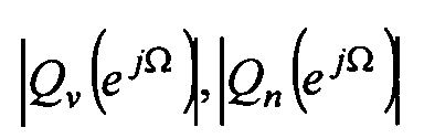
- the subspectra that can be easily separated can be clearly seen, the lower subspectrum belonging to the object at the distance R 1 being selected in the bandpass filtering.
- FIG. 5b shows the region of interest from the magnitude spectrum
Landscapes
- Engineering & Computer Science (AREA)
- Radar, Positioning & Navigation (AREA)
- Remote Sensing (AREA)
- Computer Networks & Wireless Communication (AREA)
- Physics & Mathematics (AREA)
- General Physics & Mathematics (AREA)
- Radar Systems Or Details Thereof (AREA)
Abstract
Description
Zur Linearisierung eines FMCW-Radargeräts sind verschiedene Verfahren bekannt.
In einem bekannten Verfahren wird beispielsweise ein verzögertes Sendesignal mittels einer optischen Verzögerungsleitung mit definierter Laufzeit erzeugt. Dieses verzögerte Sendesignal wird mit dem unverzögerten Sendesignal gemischt. Hieraus lässt sich die Abweichung von der idealen linearen Kennlinie ermitteln. Nachteile dieses Verfahrens sind der hohe bauliche Aufwand und die altersbedingte Eintrübung der optischen Komponenten.
- Auswählen einer vorgebbaren Anzahl L aufeinanderfolgender rampenförmiger Empfangsfolgen qk(n) des Empfangssignals mit k=1,...,L, deren Phasen arg{qk(n)} jeweils als Polynom N-ter Ordnung für den Zeitindex n mit den Polynomkoeffizienten mℓ mit ℓ=1,...,N darstellbar sind,
- Transformieren eines jeweils vorgebbaren Spektralbereichs Q(ejΩ) der ausgewählten Empfangsfolgen q(n) in ein vorgebbares Basisband, wobei jeweils Basisband-Empfangsfolgen q andk(n) mit k=0,...,L-1 erzeugt werden,
- iterative Berechnung eines Korrekturphasenterms zur Teilkompensation von
nichtlinearen Frequenzanteilen in den Basisband-Empfangsfolgen q andk (n) durch Berechnung
der Polynomkoeffizienten der einzelnen Basisband-Empfangsfolgen q andk (n) mittels Schätzverfahren, wobei q andk (n) die bereits iterativ phasenkorrigierten Folgen sind und wobei die Iteration abgebrochen wird, wenn eine vorgebbare Parameteränderung zwischen zwei aufeinanderfolgenden Iterationen unter einer vorgebbaren Schwelle ε bleibt.

- Fig. 1
- ein beispielhaftes idealisiertes rampenförmiges FMCW-Sendesignal,
- Fig. 2
- beispielhafte Darstellung der Reflexion des Radarsignals an einem punktförmigen Objekt im Abstand R,
- Fig. 3
- ein Blockdiagramm des erfindungsgemäßen Verfahrens,
- Fig. 4
- eine Darstellung einer Basisbandverschiebung eines ausgewählten Spektralbereichs im Empfangssignal,
- Fig. 5a
- eine beispielhafte Darstellung eines Betragsspektrums eines taktreduzierten Basisbandsignals vor und nach der Bandpassfilterung,
- Fig. 5b
- eine beispielhafte Darstellung eines Betragsspektrums eines Radar-Empfangssignals vor und nach der erfindungsgemäßen Phasenkorrektur.


Für die momentane Wellenlänge λ(t) ergibt sich mit der Lichtgeschwindigkeit c


Um die maximale Abweichung von diesem idealen Sendefrequenzverlauf anzugeben, wird ein maximaler relativer Linearitätsfehler als

Unter Berücksichtigung des in realen Anwendungen immer vorhandenen Rauschterms r(t) erhält man aus Gleichung (3) mit q(t)=qe(t)+r(t)






Die Bestimmung der Phasenwerte Φ(nTA) im Vektor b erfolgt mittels eines Phase-Unwrapping-Verfahrens.



Ausgangspunkt ist eine quadratische Sendesignalfolge (Chirp) mit einem Linearitätsfehler von Θ=5%, wobei die Simulationsparameter zu N=2, m2=5*1012, SNR=-18 dB, K=40 und M=64 gewählt werden. Für die weiteren Systemparameter gilt die folgende Aufstellung:
| Parameter | Wert |
| Minimal mögliche Entfernung | Rmin = 900 m |
| Maximal mögliche Entfernung | Rmax = 1100 m |
| Rampenanstiegzeit | Tr= 1ms |
| Grundfrequenz | f0 = 35 GHz |
| Frequenzhub | B = 100 MHz |
| Abtastfrequenz | fA = 2MHz |
| Spektralmittelung L | L = 20 |
| Spektralmittelung gesamt | 25 * L = 500 |
| Spektralfenster w(µ) | Hamming-Fenster |
Claims (13)
- Verfahren zur Linearisierung von frequenzmodulierten Dauerstrich-(FMCW-) Radargeräten mit nichtlinearem rampenförmig moduliertem Sendefrequenzverlauf x(t), dadurch gekennzeichnet, dass im FMCW-Radargerät empfängerseitig ein Korrekturphasenterm zur Kompensation des Phasenfehlers im Empfangssignal q(t) berechnet wird.
- Verfahren nach Anspruch 1, dadurch gekennzeichnet, dass die Berechnung des Korrekturphasenterms folgende Verfahrensschritte umfasst:Auswählen einer vorgebbaren Anzahl L aufeinanderfolgender rampenförmiger Empfangsfolgen qk(n) des Empfangssignals mit k=1,...,L, deren Phasen arg{qk(n)} jeweils als Polynom N-ter Ordnung für den Zeitindex n mit den Polynomkoeffizienten mℓ mit ℓ=1,...,N darstellbar sind,Transformieren eines jeweils vorgebbaren Spektralbereichs Q(ejΩ) der ausgewählten Empfangsfolgen q(n) in ein vorgebbares Basisband, wobei jeweils Basisband-Empfangsfolgen q andk(n) mit k=0,...,L-1 erzeugt werden,iterative Berechnung eines Korrekturphasenterms zur Teilkompensation von nichtlinearen Frequenzanteilen in den Basisband-Empfangsfolgen q andk(n) durch Berechnung der Polynomkoeffizientender einzelnen Basisband-Empfangsfolgen q andk(n) mittels Schätzverfahren, wobei q andk(n) die bereits iterativ phasenkorrigierten Folgen sind und wobei die Iteration abgebrochen wird, wenn eine vorgebbare Parameteränderung zwischen zwei aufeinanderfolgenden Iterationen unter einer vorgebbaren Schwelle ε bleibt.

- Verfahren nach Anspruch 2, dadurch gekennzeichnet, dass zur Berechnung der Polynomkoeffizientendie Entfernung
 zwischen dem das Sendesignal x(t) emittierende Radargerät und dem das Sendesignal x(t) reflektierende Objekt geschätzt wird.
- Verfahren nach Anspruch 2 und 3, dadurch gekennzeichnet, dass die Iteration folgende Verfahrensschritte umfasst:Berechnen der einzelnen diskreten Fouriertransformierten Q and (i) / k(µ) der Basisband-Empfangsfolgen q and (i) / k(n), wobei Q and (i) / k(µ)=FFT{q and (i) / k(n)} für k=1,...,L ist,Berechnen von gefilterten Basisband-Empfangsfolgen
q (i) / k(µ) mittels eines Bandpaßfilters gemäßQ (i) / k (µ) = w(µ)Q and (i) / k(µ) , wobei w(µ) ein vorgebbares Spektralfenster ist und µ den Bereich des Spektralfensters mit einem vorgebbaren Fenstermittelpunkt µmax angibt, wobei µ ∈ [µ u , µl,] mit einer vorgebbaren unteren Grenze µu und einer vorgebbaren oberen Grenze µl, ist,Berechnen der einzelnen inversen Fouriertransformiertenq (i) / k(n) der gefilterten Basisband-EmpfangsfolgenQ (i) / k(µ), wobeiq (i) / k(n)=IFFT{Q (i) / k(µ)} für k=1,...,L ist,Schätzen der Entfernungmittels eines Maximum-Likelihood-Schätzverfahrens, Berechnen der Polynomkoeffizientenaus den geschätzten Entfernungen
 ,
, Mittelung der Polynomkoeffizientenmit ℓ=1,...,N über L Empfangsfolgen q andk (n) mit k=1,...,L
 Mittelung der Entfernungen
R (i) / k über L Empfangsfolgen q andk (n),Berechnen der Empfangsfolgen q and (i+1) / k(n) mit den gemittelten geschätzten Polynomkoeffizientenals Ausgangspunkt für eine nächste Iteration.
- Verfahren nach einem der vorangehenden Ansprüche, dadurch gekennzeichnet, dass die Iteration abgebrochen wird, wenn eine vorgebbare Anzahl I von Iterationsschritten durchlaufen wurde.
- Verfahren nach Anspruch 4, dadurch gekennzeichnet, dass die Iteration abgebrochen wird, wenn die Bedingung |R (i-1) - R ( i )|< ε mit ε eine vorgebbare Schwelle erfüllt ist.
- Verfahren nach Anspruch 6, dadurch gekennzeichnet, dass die endgültigen Schätzwerte,
 mittels
 berechnet werden.
- Verfahren nach einem der Ansprüche 5-6, dadurch gekennzeichnet, dass das Spektralfenster ein Rechteck- oder Hamming-Fenster ist.
- Verfahren nach einem der Ansprüche 5-8, dadurch gekennzeichnet, dass die Position des Mittelpunkts µmax des Spektralfensters dem Maximum einer durch Mittelung der Betrags-FFT der Basisband-Empfangsfolgen |Q and (i) / k(µ)| über die Anzahl L erzeugten Betrags-FFT |Q and ( i ) (µmax)| entspricht.
- Verfahren nach einem der vorangehenden Ansprüche, dadurch gekennzeichnet, dass das Empfangssignal mit der Sendefrequenz in eine vorgebbare niedrigere Frequenzlage abgemischt wird.
- Verfahren nach einem der vorangehenden Ansprüche, dadurch gekennzeichnet, dass in einem Verfahrensschritt nach der Basisbandtransformation zur Reduktion des Abtasttakts TA der Rampensignale qk(n) die Rampensignale qk(n) mittels eines Antialias-Tiefpass gefiltert werden.
- Verfahren nach Anspruch 11, dadurch gekennzeichnet, dass der Faktor K um den der Abtasttakt TA reduziert wird, zwischen K=30 und K=60 liegt.
- Verfahren nach einem der vorangehenden Ansprüche, dadurch gekennzeichnet, dass die Anzahl der Iterationen vorgebbar ist, insbesondere beträgt die Anzahl der Iterationen zwischen 10 und 20.
Applications Claiming Priority (2)
| Application Number | Priority Date | Filing Date | Title |
|---|---|---|---|
| DE10315012 | 2003-04-02 | ||
| DE10315012A DE10315012B4 (de) | 2003-04-02 | 2003-04-02 | Verfahren zur Linearisierung von FMCW-Radargeräten |
Publications (2)
| Publication Number | Publication Date |
|---|---|
| EP1464982A2 true EP1464982A2 (de) | 2004-10-06 |
| EP1464982A3 EP1464982A3 (de) | 2005-07-27 |
Family
ID=32842221
Family Applications (1)
| Application Number | Title | Priority Date | Filing Date |
|---|---|---|---|
| EP04003829A Withdrawn EP1464982A3 (de) | 2003-04-02 | 2004-02-20 | Verfahren zur Linearisierung von FMCW-Radargeräten |
Country Status (3)
| Country | Link |
|---|---|
| US (1) | US7068216B2 (de) |
| EP (1) | EP1464982A3 (de) |
| DE (1) | DE10315012B4 (de) |
Cited By (4)
| Publication number | Priority date | Publication date | Assignee | Title |
|---|---|---|---|---|
| EP1645890A1 (de) * | 2004-10-09 | 2006-04-12 | Leica Geosystems AG | Distanzmessverfahren mit Bestimmung eines nichtidealen Chirpverlaufs |
| CN102012510A (zh) * | 2010-09-25 | 2011-04-13 | 哈尔滨工业大学 | 基于时间——相位导数分布的逆合成孔径雷达成像方法 |
| CN105301576A (zh) * | 2015-05-25 | 2016-02-03 | 中国科学院上海光学精密机械研究所 | 直视合成孔径激光成像雷达非线性校正方法 |
| CN110187317A (zh) * | 2019-06-17 | 2019-08-30 | 北京无线电测量研究所 | 一种fmcw信号非线性误差补偿方法、装置及存储介质 |
Families Citing this family (29)
| Publication number | Priority date | Publication date | Assignee | Title |
|---|---|---|---|---|
| US7570201B1 (en) * | 2004-11-05 | 2009-08-04 | Northrop Grumman Corporation | Radar exciter including phase compensation of the waveform generator |
| US20060139620A1 (en) * | 2004-12-27 | 2006-06-29 | Hopwood Francis W | Method and apparatus for coherently processing signals from incoherent sources including laser signals |
| US7170440B1 (en) * | 2005-12-10 | 2007-01-30 | Landray Technology, Inc. | Linear FM radar |
| WO2007133083A1 (en) * | 2006-05-16 | 2007-11-22 | Nederlandse Organisatie Voor Toegepast-Natuurwetenschappelijk Onderzoek Tno | Frequency modulated continuous wave radar and synthetic aperture radar |
| DE102008050117A1 (de) * | 2008-10-06 | 2010-04-08 | Endress + Hauser Gmbh + Co. Kg | Kalibration einer Radareinheit mit gerätespezifischen Korrekturkurven |
| JP2010237172A (ja) * | 2009-03-31 | 2010-10-21 | Toshiba Corp | Fmcw信号生成回路 |
| EP2302408B1 (de) * | 2009-09-17 | 2013-02-27 | Siemens Aktiengesellschaft | Verfahren zur Detektion eines Objekts mit einem FMCW-Entfernungsmesssystem |
| CN104995885A (zh) | 2013-02-05 | 2015-10-21 | 交互数字专利控股公司 | 脉冲形状正交分频复用 |
| DE102013105019A1 (de) * | 2013-05-16 | 2015-02-19 | Endress + Hauser Gmbh + Co. Kg | Füllstandsmessung mit verbesserter Entfernungsbestimmmung |
| KR101465370B1 (ko) * | 2013-12-09 | 2014-11-26 | 한국항공우주연구원 | 위상누적다항식을 이용하여 양방향 첩신호를 생성하는 장치 및 방법 |
| US9448301B2 (en) | 2013-12-20 | 2016-09-20 | Delta Mobile Systems, Inc. | Calibrated radar apparatus and associated methods |
| US9684070B2 (en) | 2013-12-20 | 2017-06-20 | Delta Mobile Systems, Inc | Radar apparatus with quiet switch calibration and associated methods |
| DE102014101904B4 (de) * | 2014-02-14 | 2024-12-19 | Endress+Hauser SE+Co. KG | Effiziente Dispersionskorrektur für FMCW-Radar in einem Rohr |
| CN103928835B (zh) * | 2014-03-20 | 2016-10-26 | 华侨大学 | 一种半导体激光器光源的非线性响应校正方法和装置 |
| US10320365B2 (en) | 2014-03-21 | 2019-06-11 | Dynaspot Corp. | Filter that minimizes in-band noise and maximizes detection sensitivity of exponentially-modulated signals |
| US11621701B2 (en) | 2014-03-21 | 2023-04-04 | Dynaspot Corp. | Filter that minimizes in-band noise and maximizes detection sensitivity of exponentially-modulated signals |
| US11025230B2 (en) | 2014-03-21 | 2021-06-01 | Dynaspot Corp. | Filter that minimizes in-band noise and maximizes detection sensitivity of exponentially-modulated signals |
| WO2015143274A1 (en) * | 2014-03-21 | 2015-09-24 | Dynaspot Corp. | A filter that minimizes in-band noise and maximizes detection sensitivity of exponentially-modulated signals |
| RU2568329C1 (ru) * | 2015-01-21 | 2015-11-20 | федеральное государственное автономное образовательное учреждение высшего образования "Южный федеральный университет" (Южный федеральный университет) | Устройство формирования линейно-частотно-модулированных сигналов |
| US10048354B2 (en) | 2015-08-13 | 2018-08-14 | Texas Instruments Incorporated | Chirp frequency non-linearity mitigation in radar systems |
| DE102017119624A1 (de) * | 2017-08-28 | 2019-04-18 | HELLA GmbH & Co. KGaA | Verfahren zum Betrieb eines Radarsystems eines Fahrzeuges |
| EP3524999B1 (de) * | 2018-02-08 | 2023-12-06 | Nxp B.V. | Eingebauter selbsttest für einen radareinheitsempfänger und verfahren dafür |
| US10969465B2 (en) * | 2018-05-01 | 2021-04-06 | Mitsubishi Electric Research Laboratories, Inc. | Reference-free nonlinearity correction for FMCW-based sensing systems |
| CN110609258B (zh) * | 2019-09-23 | 2023-06-23 | 成都盟升科技有限公司 | 基于电参数估计的调频连续波雷达成像校正方法 |
| KR102775306B1 (ko) * | 2019-11-21 | 2025-03-05 | 삼성전자주식회사 | 운동 정보 결정 방법 및 장치 |
| EP3923023A3 (de) * | 2020-05-20 | 2022-03-09 | Infineon Technologies AG | Verarbeitung von radarsignalen |
| CN113281754B (zh) * | 2021-07-26 | 2021-10-01 | 中国水利水电科学研究院 | 一种雨量站融合雷达定量估测降雨的WRF-Hydro关键参数率定方法 |
| CN114563769B (zh) * | 2022-03-03 | 2024-08-06 | 中国电子科技集团公司第三十八研究所 | 数字相控阵接收通道相位非线性的测量方法及装置 |
| CN116184349B (zh) * | 2023-02-14 | 2023-12-01 | 南通大学 | 一种基于相位回归的调频连续波雷达超分辨定位方法 |
Family Cites Families (8)
| Publication number | Priority date | Publication date | Assignee | Title |
|---|---|---|---|---|
| US4539565A (en) * | 1982-08-16 | 1985-09-03 | The Boeing Company | FM/CW radar linearization network and method therefor |
| US5172123A (en) * | 1985-01-29 | 1992-12-15 | Hercules Defense Electronics, Inc. | Frequency feedback linearizer |
| DE4104792A1 (de) * | 1991-02-16 | 1992-08-20 | Bosch Gmbh Robert | Fmcw-radarsystem mit linearer frequenzmodulation |
| GB9103945D0 (en) * | 1991-02-26 | 1991-06-12 | Philips Electronic Associated | Linearizing a swept-frequency radar |
| FR2691809B1 (fr) * | 1992-05-26 | 1994-09-02 | Thomson Csf | Procédé de compensation automatique de la non linéarité de la pente de modulation d'un radar à onde continue modulée en fréquence et radar pour sa mise en Óoeuvre. |
| US5719580A (en) * | 1996-06-06 | 1998-02-17 | Trw Inc. | Method and apparatus for digital compensation of VCO nonlinearity in a radar system |
| WO1998038523A1 (de) * | 1997-02-28 | 1998-09-03 | Siemens Aktiengesellschaft | Verfahren und vorrichtung zur entfernungs- und geschwindigkeitsmessung |
| DE10018552A1 (de) * | 2000-04-14 | 2001-10-18 | Bosch Gmbh Robert | Verfahren zur Erfassung und Korrektur von Nichtlinearitäten in einem Mikrowellenradarsystem |
-
2003
- 2003-04-02 DE DE10315012A patent/DE10315012B4/de not_active Expired - Fee Related
-
2004
- 2004-02-20 EP EP04003829A patent/EP1464982A3/de not_active Withdrawn
- 2004-04-02 US US10/816,662 patent/US7068216B2/en not_active Expired - Fee Related
Cited By (10)
| Publication number | Priority date | Publication date | Assignee | Title |
|---|---|---|---|---|
| EP1645890A1 (de) * | 2004-10-09 | 2006-04-12 | Leica Geosystems AG | Distanzmessverfahren mit Bestimmung eines nichtidealen Chirpverlaufs |
| WO2006040263A1 (de) * | 2004-10-09 | 2006-04-20 | Leica Geosystems Ag | Elektrooptisches distanzmessverfahren mit bestimmung eines nichtidealen chirpverlaufs |
| JP2008516213A (ja) * | 2004-10-09 | 2008-05-15 | ライカ ジオシステムズ アクチェンゲゼルシャフト | 非理想的チャープ形状の決定による電気光学的距離測定方法 |
| AU2005293591B2 (en) * | 2004-10-09 | 2009-10-29 | Leica Geosystems Ag | Electro-optical method for measuring distance and detecting a non-ideal chirp profile |
| US7671971B2 (en) | 2004-10-09 | 2010-03-02 | Leica Geosystems Ag | Electro-optical method for measuring distance and detecting a non-ideal chirp profile |
| CN101036068B (zh) * | 2004-10-09 | 2010-05-05 | 莱卡地球系统公开股份有限公司 | 用于测距及检测非理想线性调频脉冲曲线的电光方法 |
| CN102012510A (zh) * | 2010-09-25 | 2011-04-13 | 哈尔滨工业大学 | 基于时间——相位导数分布的逆合成孔径雷达成像方法 |
| CN105301576A (zh) * | 2015-05-25 | 2016-02-03 | 中国科学院上海光学精密机械研究所 | 直视合成孔径激光成像雷达非线性校正方法 |
| CN105301576B (zh) * | 2015-05-25 | 2018-01-09 | 中国科学院上海光学精密机械研究所 | 直视合成孔径激光成像雷达非线性校正方法 |
| CN110187317A (zh) * | 2019-06-17 | 2019-08-30 | 北京无线电测量研究所 | 一种fmcw信号非线性误差补偿方法、装置及存储介质 |
Also Published As
| Publication number | Publication date |
|---|---|
| US7068216B2 (en) | 2006-06-27 |
| DE10315012A1 (de) | 2004-10-28 |
| DE10315012B4 (de) | 2005-05-12 |
| EP1464982A3 (de) | 2005-07-27 |
| US20050001761A1 (en) | 2005-01-06 |
Similar Documents
| Publication | Publication Date | Title |
|---|---|---|
| EP1464982A2 (de) | Verfahren zur Linearisierung von FMCW-Radargeräten | |
| EP1516203B1 (de) | Verfahren zur unterdr ckung von st rungen in systemen z ur objekterfassung | |
| DE102009000468B4 (de) | Radarverfahren und -systeme mit Rampensequenzen | |
| EP3538922B1 (de) | Radarsensor für kraftfahrzeuge | |
| DE102018102816B3 (de) | Radar mit phasenkorrektur | |
| DE19757309C1 (de) | Verfahren zur Verarbeitung von Spotlight SAR-Rohdaten | |
| EP1984707B1 (de) | Paarweise zf-abtastung für puls-laufzeit-füllstandsensoren | |
| DE19822957C1 (de) | Verfahren zur Detektion und Unterdrückung von Störsignalen in SAR-Daten und Einrichtung zur Durchführung des Verfahrens | |
| DE4427657C2 (de) | Verfahren zur Bilderzeugung mittels einer zweidimensionalen Datenverarbeitung bei einem Radar mit synthetischer Apertur | |
| EP0677172B1 (de) | Computerisiertes radarverfahren zur messung von abständen und relativgeschwindigkeiten zwischen einem fahrzeug und vor ihm befindlichen hindernissen | |
| DE69507954T2 (de) | Verfahren und vorrichtung zur milderung der entfernung-doppler-mehrdeutigkeiten in puls-doppler-radar-geräten | |
| EP1043601B1 (de) | Radarverfahren zur Messung von Abständen und Relativgeschwindigkeiten zwischen einem Fahrzeug und einem oder mehreren Hindernissen | |
| WO2015018586A1 (de) | Dispersionskorrektur für fmcw-radar in einem rohr | |
| DE102018123383A1 (de) | Radarerfassung mit Störungsunterdrückung | |
| EP1296157B1 (de) | Verfahren zur Kalibrierung der Radarsignale an den Subaperturen der Antenne eines zweikanaligen SAR/MTI Radarsystems | |
| DE102008050117A1 (de) | Kalibration einer Radareinheit mit gerätespezifischen Korrekturkurven | |
| DE10226508A1 (de) | Verfahren zur Detektion sowie Geschwindigkeits- und Positionsschätzung von bewegten Objekten in SAR-Bildern | |
| DE4122592C1 (de) | ||
| EP3385750A1 (de) | Verfahren und vorrichtung zur verarbeitung von sar-rohdaten | |
| WO2016096207A1 (de) | Verfahren und vorrichtung zum betreiben eines radarsystems eines kraftfahrzeugs | |
| DE102018202864A1 (de) | Verfahren und System für Synthetische-Apertur-Radarsignalverarbeitung | |
| WO2014173866A1 (de) | Messverfahren und messgerät zur vermessung von breitbandigen messsignalen | |
| DE4117849C2 (de) | Verfahren zur Generierung einer Referenzfunktion für eine Impulskompression von frequenz-, phasen- und/oder amplitudenmodulierten Signalen | |
| DE102021207032A1 (de) | SA-Radarsensor für Kraftfahrzeuge | |
| DE102008050327A1 (de) | Empfangsmischer zur Verringerung von Überkopplungseffekten |
Legal Events
| Date | Code | Title | Description |
|---|---|---|---|
| PUAI | Public reference made under article 153(3) epc to a published international application that has entered the european phase |
Free format text: ORIGINAL CODE: 0009012 |
|
| AK | Designated contracting states |
Kind code of ref document: A2 Designated state(s): AT BE BG CH CY CZ DE DK EE ES FI FR GB GR HU IE IT LI LU MC NL PT RO SE SI SK TR |
|
| AX | Request for extension of the european patent |
Extension state: AL LT LV MK |
|
| PUAL | Search report despatched |
Free format text: ORIGINAL CODE: 0009013 |
|
| AK | Designated contracting states |
Kind code of ref document: A3 Designated state(s): AT BE BG CH CY CZ DE DK EE ES FI FR GB GR HU IE IT LI LU MC NL PT RO SE SI SK TR |
|
| AX | Request for extension of the european patent |
Extension state: AL LT LV MK |
|
| 17P | Request for examination filed |
Effective date: 20051014 |
|
| AKX | Designation fees paid |
Designated state(s): DE FR GB |
|
| STAA | Information on the status of an ep patent application or granted ep patent |
Free format text: STATUS: THE APPLICATION HAS BEEN WITHDRAWN |
|
| 18W | Application withdrawn |
Effective date: 20110727 |