EP1465007B1 - Befestigungsvorrichtung zur Sicherung von einem Kameramonitor an einem Kamerastativ - Google Patents
Befestigungsvorrichtung zur Sicherung von einem Kameramonitor an einem Kamerastativ Download PDFInfo
- Publication number
- EP1465007B1 EP1465007B1 EP03252163A EP03252163A EP1465007B1 EP 1465007 B1 EP1465007 B1 EP 1465007B1 EP 03252163 A EP03252163 A EP 03252163A EP 03252163 A EP03252163 A EP 03252163A EP 1465007 B1 EP1465007 B1 EP 1465007B1
- Authority
- EP
- European Patent Office
- Prior art keywords
- camera
- arm
- anchoring device
- anchoring
- monitor
- Prior art date
- Legal status (The legal status is an assumption and is not a legal conclusion. Google has not performed a legal analysis and makes no representation as to the accuracy of the status listed.)
- Expired - Lifetime
Links
- 238000004873 anchoring Methods 0.000 title claims abstract description 65
- 238000010276 construction Methods 0.000 description 2
- 238000000034 method Methods 0.000 description 1
- 238000012544 monitoring process Methods 0.000 description 1
- 230000000284 resting effect Effects 0.000 description 1
- 230000000717 retained effect Effects 0.000 description 1
Images




Classifications
-
- F—MECHANICAL ENGINEERING; LIGHTING; HEATING; WEAPONS; BLASTING
- F16—ENGINEERING ELEMENTS AND UNITS; GENERAL MEASURES FOR PRODUCING AND MAINTAINING EFFECTIVE FUNCTIONING OF MACHINES OR INSTALLATIONS; THERMAL INSULATION IN GENERAL
- F16M—FRAMES, CASINGS OR BEDS OF ENGINES, MACHINES OR APPARATUS, NOT SPECIFIC TO ENGINES, MACHINES OR APPARATUS PROVIDED FOR ELSEWHERE; STANDS; SUPPORTS
- F16M13/00—Other supports for positioning apparatus or articles; Means for steadying hand-held apparatus or articles
- F16M13/02—Other supports for positioning apparatus or articles; Means for steadying hand-held apparatus or articles for supporting on, or attaching to, an object, e.g. tree, gate, window-frame, cycle
-
- F—MECHANICAL ENGINEERING; LIGHTING; HEATING; WEAPONS; BLASTING
- F16—ENGINEERING ELEMENTS AND UNITS; GENERAL MEASURES FOR PRODUCING AND MAINTAINING EFFECTIVE FUNCTIONING OF MACHINES OR INSTALLATIONS; THERMAL INSULATION IN GENERAL
- F16M—FRAMES, CASINGS OR BEDS OF ENGINES, MACHINES OR APPARATUS, NOT SPECIFIC TO ENGINES, MACHINES OR APPARATUS PROVIDED FOR ELSEWHERE; STANDS; SUPPORTS
- F16M11/00—Stands or trestles as supports for apparatus or articles placed thereon ; Stands for scientific apparatus such as gravitational force meters
- F16M11/02—Heads
- F16M11/04—Means for attachment of apparatus; Means allowing adjustment of the apparatus relatively to the stand
- F16M11/06—Means for attachment of apparatus; Means allowing adjustment of the apparatus relatively to the stand allowing pivoting
- F16M11/10—Means for attachment of apparatus; Means allowing adjustment of the apparatus relatively to the stand allowing pivoting around a horizontal axis
-
- F—MECHANICAL ENGINEERING; LIGHTING; HEATING; WEAPONS; BLASTING
- F16—ENGINEERING ELEMENTS AND UNITS; GENERAL MEASURES FOR PRODUCING AND MAINTAINING EFFECTIVE FUNCTIONING OF MACHINES OR INSTALLATIONS; THERMAL INSULATION IN GENERAL
- F16M—FRAMES, CASINGS OR BEDS OF ENGINES, MACHINES OR APPARATUS, NOT SPECIFIC TO ENGINES, MACHINES OR APPARATUS PROVIDED FOR ELSEWHERE; STANDS; SUPPORTS
- F16M11/00—Stands or trestles as supports for apparatus or articles placed thereon ; Stands for scientific apparatus such as gravitational force meters
- F16M11/20—Undercarriages with or without wheels
- F16M11/2007—Undercarriages with or without wheels comprising means allowing pivoting adjustment
- F16M11/2014—Undercarriages with or without wheels comprising means allowing pivoting adjustment around a vertical axis
-
- F—MECHANICAL ENGINEERING; LIGHTING; HEATING; WEAPONS; BLASTING
- F16—ENGINEERING ELEMENTS AND UNITS; GENERAL MEASURES FOR PRODUCING AND MAINTAINING EFFECTIVE FUNCTIONING OF MACHINES OR INSTALLATIONS; THERMAL INSULATION IN GENERAL
- F16M—FRAMES, CASINGS OR BEDS OF ENGINES, MACHINES OR APPARATUS, NOT SPECIFIC TO ENGINES, MACHINES OR APPARATUS PROVIDED FOR ELSEWHERE; STANDS; SUPPORTS
- F16M11/00—Stands or trestles as supports for apparatus or articles placed thereon ; Stands for scientific apparatus such as gravitational force meters
- F16M11/20—Undercarriages with or without wheels
- F16M11/2085—Undercarriages with or without wheels comprising means allowing sideward adjustment, i.e. left-right translation of the head relatively to the undercarriage
Definitions
- the invention relates to an anchoring device for a camera monitor, more particularly to an anchoring device adapted to be mounted on a camera connecting plate of a camera stand so as to anchor a camera monitor on the camera stand.
- US 5,797,568 discloses a multi-position television monitor stand which can be adjusted to accommodate different monitor sizes by adj usting the width and height of the various components of the stand.
- US 5, 326, 058 discloses a monitor mounting plate for video equipment.
- the mounting plate is arranged such that the monitor moves commensurately with the video equipment and the plate is configured to allow it to fit with a range of tripod/camera combinations.
- US 6,374,752 discloses an ergonomic computer workstation having U-shaped frames for mounting a monitor.
- US 6,305,973 discloses an articulable projecting plug comprising a U-shaped frame.
- US 4,341,452 discloses a triaxial universal camera mount assembly which permits a camera secured thereto to be independently or simultaneously pivotable about three axis.
- DE 19519528 discloses a support device for a video camera.
- the video camera is located within a first bracket which has bearing support points connected with pivot point bearings on a second U-shape bracket and an L-shaped bracket is pivotably mounted on the first bracket and has a fixing point that can support a monitor.
- FIG. 1 the bottom side of a camera 10 is connected to a camera connecting plate 12 to permit mounting of the camera 10 on a camera stand 11.
- the camera 10 is provided with a video output port (not shown) for connection to a monitor, thereby permitting real-time monitoring of the images captured by the camera 10.
- Figures 1 and 2 illustrate a conventional camera monitor 14 that is mounted directly on the camera 10 with the use of an anchoring device 13.
- the anchoring device 13 includes an elongate first arm 131 and a pair of second arms 132 which extend transversely from opposite ends of the first arm 131.
- the second arms 132 have free ends that are connected pivotally and respectively to opposite lateral sides of the camera monitor 14.
- the anchoring device 13 further includes an anchoring plate 133 having one end connected to a lower side of the first arm 131. The other end of the anchoring plate 133 is fastened onto the top side of the camera 10 with the use of screws.
- the camera monitor 14 is connected to the video output port of the camera 10 through a signal cable (not shown).
- the object of the present invention is to provide an anchoring device for anchoring a camera monitor on a camera stand that can overcome the aforesaid drawbacks associated with the prior art.
- the anchoring device of the present invention is adapted to be mounted on a camera connecting plate of a camera stand so as to anchor a camera monitor on the camera stand, and comprises an anchoring member and a mounting frame unit.
- the anchoring member has a plate connecting portion adapted to be mounted fixedly on the camera connecting plate, and a frame connecting portion opposite to the plate connecting portion in a longitudinal direction.
- the mounting frame unit is mounted on the frame connecting portion, is adapted for mounting the camera monitor on the anchoring member, and includes inner and outer frame members.
- the inner frame member is adapted to be mounted with the camera monitor, and has a first inner arm and a pair of second inner arms which extend transversely from opposite ends of the first inner arm.
- the outer frame member is mounted on the frame connecting portion, and has a first outer arm and a pair of second outer arms which extend transversely from opposite ends of the first outer arm.
- Each of the second outer arms has a distal end connected pivotally to a distal end of a respective one of the second inner arms such that the inner frame member is movably disposed in the outer frame member
- the mounting frame unit further includes a fastener for fastening adjustably the camera monitor on the first inner arm.
- the first inner arm is formed with a slide slot therealong. The fastener extending through the slide slot and being adapted to engage threadedly the camera monitor.
- the bottom side 211 of a camera 21 is connected to a camera connecting plate 23 to permit mounting of the camera 21 on a platform 221 of a camera stand 22.
- the anchoring device 3 of the present invention is used to anchor a camera monitor 24 at the vicinity of the camera 21.
- the camera monitor 24 will be positioned near the camera 21.
- the camera connecting plate 23 is stacked on the platform 221 of the camera stand 22, there is no space available on the platform 221 for mounting the anchoring device 3.
- the anchoring device 3 of this invention is preferably adapted to be mounted in the space between the camera 21 and the camera connecting plate 23 so that the camera monitor 24 can be positioned near the camera 21 without altering the original designs of the camera 21, the camera connecting plate 23, and the camera stand 22. Nevertheless, if the original designs of the camera connecting plate 23 and the camera stand 22 are not to be maintained, it is apparent to those skilled in the art that the anchoring device 3 may be mounted on any other appropriate position on the camera connecting plate 23 or the camera stand 22.
- the preferred embodiment of the anchoring device 3 includes an anchoring member 4 and a mounting frame unit 5.
- the anchoring member 4 has a plate connecting portion 41 adapted to be mounted fixedly on the camera connecting plate 23, such as with the use of screws, and a frame connecting portion 42 opposite to the plate connecting portion 41 in a longitudinal direction.
- the frame connecting portion 42 projects relative to a right lateral side of the camera connecting plate 23.
- the mounting frame unit 5 is mounted on the frame connecting portion 42 and is adapted for mounting the camera monitor 24 on the anchoring member 4.
- the mounting frame unit 5 includes an inner frame member 51 and an outer frame member 52.
- the inner frame member 51 is adapted to be mounted with the camera monitor 24, and has a first inner arm 511 and a pair of second inner arms 512 which extend transversely from opposite ends of the first inner arm 511.
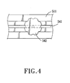
- the first inner arm 511 is formed with a slide slot 541 therealong.
- a fastener 542 extends through the slide slot 541 and is adapted to engage threadedly the camera monitor 24 for fastening adjustably the camera monitor 24 on the first inner arm 511. Therefore, as shown in Figure 6, unlike the conventional anchoring manner of anchoring the camera monitor 24 at two fixedpoints, this embodiment practices single-point anchoring in view of the threaded engagement between the fastener 542 and the bottom side of the camera monitor 24. In this manner, it is no longer required to match the distance between the second inner arms 512 with the width of the camera monitor 24. Instead, what is required in this embodiment is that the width of the camera monitor 24 should be smaller than the distance between the second inner arms 512.
- the fastener 542 can be loosened from the camera monitor 24 so as to permit movement of the camera monitor 24 along the slide slot 541, and can be subsequently tightened on the camera monitor 24 so as to retain the camera monitor 24 at a desired position on the first inner arm 511.
- the outer frame member 52 is mounted on the frame connecting portion 42, and has a first outer arm 521 and a pair of second outer arms 522 which extend transversely from opposite ends of the first outer arm 521.
- the first outer arm 521 is slightly longer than the first inner arm 511.
- Each of the second outer arms 522 is slightly longer than the second inner arms 512.
- each of the second outer arms 522 has a distal end connected pivotally to a distal end of a respective one of the second inner arms 512 such that the inner frame member 51 is movably disposed in the outer frame member 52. Accordingly, tilt of the camera monitor 24 can be adjusted, as best shown in Figure 7.
- the mounting frame unit 5 further includes a connecting member 55 for mounting adjustably the first outer arm 521 on the frame connecting portion 42 of the anchoring member 4.
- the connecting member 55 includes a head portion 552 movably connected to the first outer arm 521 in the slide slot 551, an upright rod 553 connected at one end to the head portion 552, an engaging member 554 having a first end 556 movably disposed on the rod 553 and a second end, and a releasable fastener 555 for interconnecting releasably and non-rotatably the second end of the engaging member 554 and the frame connecting portion 42 of the anchoring member 4.
- the releasable fastener 555 which is conventional in construction, is mounted on the frame connecting portion 42 of the anchoring member 4, has one side formed with an insert slot 558, and includes a release button 559.
- a spring-loaded mechanism (not shown) of the fastener 555.
- the release button 559 is pressed, the spring-loaded mechanism will be disengaged from the second end of the engaging member 554 so as to permit removal of the latter from the insert slot 558.
- the first end 556 of the engaging member 554 is tubular and is sleeved slidably and rotatably on the rod 553.
- the connecting member 55 further includes a releasable locking unit 557 for arresting selectively relative movement between the first end 556 of the engaging member 554 and the rod 553.
- the locking unit 557 is rotated in a first direction
- the first end 556 of the engaging member 554 is tightened on the rod 553.
- the first end 556 of the engaging member 554 is loosened from the rod 553 such that the rod 553 can move up and down or rotate relative to the first end 556 of the engaging member 554. Since the specific configuration of the locking unit 557 is known in the art, a detailed description of the same will be omitted herein for the sake of brevity.
- the head portion 552 can be slid along the slide groove 551 to move the outer frame member 52 relative to the rod 553, as shown in Figure 8.
- the rod 553 can be moved up and down so as to adjust the height of the camera monitor 24, and the engaging member 554 can be rotated about the rod 553 within a 360-degree range, as shown in Figure 9.
- the anchoring device 3 of this invention allows the camera monitor 24 to be tilted up and down, moved to the left and to the right, and rotated within a 360-degree range as desired by the user to ease viewing restrictions commonly encountered in the prior art.
- the mounting frame unit 5 further includes a support member 53 that has a first arm portion 531 and a pair of second arm portions 532 which extend transversely from opposite ends of the first arm portion 531 and which have distal ends connected transversely and respectively to the distal ends of the second inner arms 512.
- the first arm portion 531 of the support member 53 serves to abut against the rear side of the camera monitor 24 for providing added support to the latter, as best shown in Figure 5.
- the plate connecting portion 41 of the anchoring member 4 is first fastened onto the camera connecting plate 23.
- the fastener 542 is used to mount the camera monitor 24 on the inner frame member 51.
- the camera 21 is secured on the camera connecting plate 23, and the assembly of the camera 21 and the camera connecting plate 23 is subsequently mounted on the platform 221 of the camera stand 22.
- the second end of the engaging member 554 is inserted into the insert slot 558 to complete the process of anchoring the camera monitor 24 on the camera stand 22.
- the anchoring device 3 is illustrated as being mounted on the right side of the camera 21, it is apparent to those skilled in the art that the mounting position of the anchoring device 3 can be flexibly adjusted to suit the user's needs.
- the anchoring device 3 may be mounted such that the camera monitor 24 thereon can act as a camera viewfinder.
- the anchoring device 3 of this invention has the following advantages:
- the camera monitor 24 when the camera monitor 24 is not in use, it is only required to press the release button 559 to permit removal of the mounting frame unit 5 from the anchoring member 4, which is more convenient as compared to the complicated screw-removal operations needed when removing the camera monitor from the conventional anchoring device.
Landscapes
- Engineering & Computer Science (AREA)
- General Engineering & Computer Science (AREA)
- Mechanical Engineering (AREA)
- Studio Devices (AREA)
- Accessories Of Cameras (AREA)
- Camera Bodies And Camera Details Or Accessories (AREA)
Claims (6)
- Verankerungsvorrichtung (3), die eingerichtet ist, um an einer Kameraverbindungsplatte (23) eines Kamerastativs (22) angebracht zu sein, um einen Kameramonitor bzw. eine Kamerakontrolleinrichtung (24) an dem Kamerastativ (22) zu verankern, wobei die Verankerungsvorrichtung (3) Folgendes enthält:ein Verankerungsglied (4), das einen Plattenverbindungsabschnitt (41), der eingerichtet ist, um starr an der Kameraverbindungsplatte (23) angebracht zu sein, und einen Rahmenverbindungsabschnitt (42) hat, und zwar entgegengesetzt zu dem Plattenverbindungsabschnitt (41) in einer Längsrichtung, undeine Anbringungsrahmeneinheit (5), die an dem Rahmenverbindungsabschnitt (42) angebracht ist und zum Anbringen des Kameramonitors bzw. der Kamerakontrolleinrichtung (24) an dem Verankerungsglied (4) eingerichtet ist,wobei jeder der zweiten äußeren Arme (522) ein distales Ende hat, das schwenkbar bzw. drehbar mit einem distalen Ende eines jeweiligen Armes der zweiten inneren Arme (512) verbunden ist;
wobei die Anbringungsrahmeneinheit (5) Folgendes enthält:ein inneres Rahmenglied (51), das eingerichtet ist, um an dem Kameramonitor bzw. der Kamerakontrolleinrichtung (24) angebracht zu sein, und einen ersten inneren Arm (511) und ein Paar zweite innere Arme (512) hat, welche sich quer von den entgegengesetzten Enden des ersten inneren Armes (511) erstrecken; undein äußeres Rahmenglied (52), das an dem Rahmenverbindungsabschnitt (42) angebracht ist und einen ersten äußeren Arm (521) und ein Paar zweite äußere Arme (522) hat, welche sich quer von entgegengesetzten Enden des ersten äußeren Armes (521) erstrecken;
wobei das innere Rahmenglied (51) bewegbar an dem äußeren Rahmenglied (52) angeordnet ist, wobei die Anbringungsrahmeneinheit (5) ferner ein Befestigungselement (542) zum justierbaren Befestigen des Kameramonitors bzw. der Kamerakontrolleinrichtung (24) an dem ersten inneren Arm (511) enthält, und wobei der erste innere Arm (511) mit einem Gleitschlitz (541) da entlang gebildet ist, wobei sich das Befestigungselement (542) durch den Gleitschlitz (541) erstreckt und eingerichtet ist, um gewindemäßig mit dem Kameramonitor bzw. der Kamerakontrolleinrichtung (24) im Eingriff zu sein. - Verankerungsvorrichtung (3), wie in Anspruch 1 beansprucht, wobei die Anbringungsrahmeneinheit (5) ferner ein Trage- bzw. Stützglied (53) enthält, wobei das Trage- bzw. Stützglied (53) einen ersten Armabschnitt (531) und ein Paar zweite Armabschnitte (532) enthält, welche sich quer von den entgegengesetzten Enden des ersten Armabschnittes (531) erstrecken und welche distale Enden haben, die quer und jeweils mit den distalen Enden der zweiten inneren Arme (512) verbunden sind.
- Verankerungsvorrichtung (3), wie in Anspruch 1 beansprucht, wobei die Anbringungsrahmeneinheit (5) ferner ein Verbindungsglied (55) zum justierbaren Anbringen des ersten äußeren Armes (521) an dem Rahmenverbindungsabschnitt (42) enthält.
- Verankerungsvorrichtung (3), wie in Anspruch 3 beansprucht, wobei ferner der erste äußere Arm (521) mit einem Gleitschlitz (551) da entlang gebildet ist, wobei das Verbindungsglied (55), das einen Kopfabschnitt (552) hat, bewegbar mit dem ersten äußeren Arm (521) in dem Gleitschlitz (551) verbunden ist.
- Verankerungsvorrichtung (3), wie in Anspruch 4 beansprucht, wobei das Verbindungsglied (55) ferner Folgendes enthält:eine aufrechte bzw. senkrechte Stange (553), die mit einem Ende mit dem Kopfabschnitt (552) verbunden ist;ein Eingriffsglied (554), das ein erstes Ende (556), das bewegbar an der Stange (553) angeordnet ist, und ein zweites Ende hat;
undein freigebbares bzw. lösbares Befestigungselement (555) zum freigebbaren bzw.lösbaren und nicht drehbaren miteinander Verbinden des zweiten Endes des Eingriffsgliedes (554) und des Rahmenverbindungsabschnittes (42). - Verankerungsvorrichtung (3), wie in Anspruch 5 beansprucht, wobei das erste Ende (556) des Eingriffsgliedes (554) röhrenförmig ist und buchsenmäßig bzw. hüllenmäßig an der Stange (553) drehbar ist, wobei das Verbindungsglied (55) ferner eine freigebbare bzw. lösbare Verriegelungs- bzw. Klemmeinheit (557) zum wahlweisen Hemmen bzw. Arretieren relativer Bewegung zwischen dem ersten Ende (556) des Eingriffsgliedes (554) und der Stange (553) enthält.
Priority Applications (3)
| Application Number | Priority Date | Filing Date | Title |
|---|---|---|---|
| AT03252163T ATE334427T1 (de) | 2003-04-04 | 2003-04-04 | Befestigungsvorrichtung zur sicherung von einem kameramonitor an einem kamerastativ |
| DE60307043T DE60307043D1 (de) | 2003-04-04 | 2003-04-04 | Befestigungsvorrichtung zur Sicherung von einem Kameramonitor an einem Kamerastativ |
| EP03252163A EP1465007B1 (de) | 2003-04-04 | 2003-04-04 | Befestigungsvorrichtung zur Sicherung von einem Kameramonitor an einem Kamerastativ |
Applications Claiming Priority (1)
| Application Number | Priority Date | Filing Date | Title |
|---|---|---|---|
| EP03252163A EP1465007B1 (de) | 2003-04-04 | 2003-04-04 | Befestigungsvorrichtung zur Sicherung von einem Kameramonitor an einem Kamerastativ |
Publications (2)
| Publication Number | Publication Date |
|---|---|
| EP1465007A1 EP1465007A1 (de) | 2004-10-06 |
| EP1465007B1 true EP1465007B1 (de) | 2006-07-26 |
Family
ID=32842853
Family Applications (1)
| Application Number | Title | Priority Date | Filing Date |
|---|---|---|---|
| EP03252163A Expired - Lifetime EP1465007B1 (de) | 2003-04-04 | 2003-04-04 | Befestigungsvorrichtung zur Sicherung von einem Kameramonitor an einem Kamerastativ |
Country Status (3)
| Country | Link |
|---|---|
| EP (1) | EP1465007B1 (de) |
| AT (1) | ATE334427T1 (de) |
| DE (1) | DE60307043D1 (de) |
Families Citing this family (4)
| Publication number | Priority date | Publication date | Assignee | Title |
|---|---|---|---|---|
| JP5542176B2 (ja) * | 2010-01-22 | 2014-07-09 | 株式会社日本ビデオシステム | ビューファインダー装置固定用アダプタ |
| CN107343123A (zh) * | 2017-08-07 | 2017-11-10 | 恒银金融科技股份有限公司 | 一种金融设备摄像装置调节机构 |
| CN111866472B (zh) * | 2020-08-04 | 2022-05-20 | 江苏省华海消防工程安装有限公司 | 一种消防监控管理系统及消防监控控制方法 |
| CN112032535B (zh) * | 2020-09-23 | 2025-05-02 | 浙江赛龙建设科技有限公司 | 一种用于工厂的监控安防设备 |
Family Cites Families (6)
| Publication number | Priority date | Publication date | Assignee | Title |
|---|---|---|---|---|
| US4341452A (en) * | 1981-08-10 | 1982-07-27 | Torkel Korling | Triaxial universal camera mount |
| US5611513A (en) * | 1992-01-31 | 1997-03-18 | Rosen; John B. | Articulable projecting plug |
| US5326058A (en) * | 1993-06-14 | 1994-07-05 | Avalon Video, Inc. | Monitor mounting plate for video equipment |
| DE19519528C2 (de) * | 1995-05-27 | 1999-01-21 | Tobias Steidle | Haltevorrichtung für kompakte Bildaufzeichnungsgeräte zur stabilisierten Bildaufnahme bei bewegtem Bildaufzeichnungsgerät |
| ES1034279U (es) * | 1996-05-30 | 1996-12-16 | Telefonica Nacional Espana Co | Soporte poliposicionable para monitores de television. |
| US6374752B1 (en) * | 2000-03-13 | 2002-04-23 | Glenn E. Walser | Ergonomic computer workstation |
-
2003
- 2003-04-04 EP EP03252163A patent/EP1465007B1/de not_active Expired - Lifetime
- 2003-04-04 AT AT03252163T patent/ATE334427T1/de not_active IP Right Cessation
- 2003-04-04 DE DE60307043T patent/DE60307043D1/de not_active Expired - Lifetime
Also Published As
| Publication number | Publication date |
|---|---|
| DE60307043D1 (de) | 2006-09-07 |
| ATE334427T1 (de) | 2006-08-15 |
| EP1465007A1 (de) | 2004-10-06 |
Similar Documents
| Publication | Publication Date | Title |
|---|---|---|
| US8029197B2 (en) | Hand-held image stabilization and balancing system for cameras | |
| US6439515B1 (en) | Video camera support device | |
| US5332136A (en) | Support apparatus for an optical instrument | |
| US5119203A (en) | Monitor mounting fixture | |
| US7563038B2 (en) | Support for a camcorder | |
| JP2004229274A (ja) | カメラあるいはビデオカメラを固定するための肩装着型カメラ支持装置 | |
| US5767906A (en) | Viewfinder mounting for video camera | |
| US20040223078A1 (en) | Support for hand held video camera | |
| US20190064638A1 (en) | Holder for mobile devices | |
| US5940644A (en) | Balancing apparatus for stabilizing camera movement | |
| US6862407B2 (en) | Camera stabilizer platform and camcorder therefor | |
| EP1465007B1 (de) | Befestigungsvorrichtung zur Sicherung von einem Kameramonitor an einem Kamerastativ | |
| US7372502B2 (en) | Camera stabilizer | |
| US20090256035A1 (en) | Instrument-mounting head with balance control | |
| US7097368B2 (en) | Camera stabilizer | |
| JP2019045690A (ja) | ジンバル装置 | |
| US20090263118A1 (en) | Camera-mounting head with balance control | |
| GB2425185A (en) | Camera support and associated apparatus | |
| US12313218B2 (en) | Television support tilt mechanism | |
| US7025313B2 (en) | Side wing support adaptor accommodating accessory of tripod | |
| US20060268156A1 (en) | Stabilizer platform for a camcorder | |
| JPH11257584A (ja) | 三脚移動用車輪 | |
| CN220707015U (zh) | 一种具有调节功能的双肩固定式摄像机托架 | |
| JP3594590B1 (ja) | カメラ用把手付三脚 | |
| CN118935219A (zh) | 一种基于三轴云台稳定摄像装置系统 |
Legal Events
| Date | Code | Title | Description |
|---|---|---|---|
| PUAI | Public reference made under article 153(3) epc to a published international application that has entered the european phase |
Free format text: ORIGINAL CODE: 0009012 |
|
| AK | Designated contracting states |
Kind code of ref document: A1 Designated state(s): AT BE BG CH CY CZ DE DK EE ES FI FR GB GR HU IE IT LI LU MC NL PT RO SE SI SK TR |
|
| AX | Request for extension of the european patent |
Extension state: AL LT LV MK |
|
| 17P | Request for examination filed |
Effective date: 20050404 |
|
| 17Q | First examination report despatched |
Effective date: 20050518 |
|
| AKX | Designation fees paid |
Designated state(s): AT BE BG CH CY CZ DE DK EE ES FI FR GB GR HU IE IT LI LU MC NL PT RO SE SI SK TR |
|
| GRAP | Despatch of communication of intention to grant a patent |
Free format text: ORIGINAL CODE: EPIDOSNIGR1 |
|
| GRAS | Grant fee paid |
Free format text: ORIGINAL CODE: EPIDOSNIGR3 |
|
| GRAA | (expected) grant |
Free format text: ORIGINAL CODE: 0009210 |
|
| AK | Designated contracting states |
Kind code of ref document: B1 Designated state(s): AT BE BG CH CY CZ DE DK EE ES FI FR GB GR HU IE IT LI LU MC NL PT RO SE SI SK TR |
|
| PG25 | Lapsed in a contracting state [announced via postgrant information from national office to epo] |
Ref country code: IT Free format text: LAPSE BECAUSE OF FAILURE TO SUBMIT A TRANSLATION OF THE DESCRIPTION OR TO PAY THE FEE WITHIN THE PRESCRIBED TIME-LIMIT;WARNING: LAPSES OF ITALIAN PATENTS WITH EFFECTIVE DATE BEFORE 2007 MAY HAVE OCCURRED AT ANY TIME BEFORE 2007. THE CORRECT EFFECTIVE DATE MAY BE DIFFERENT FROM THE ONE RECORDED. Effective date: 20060726 Ref country code: CZ Free format text: LAPSE BECAUSE OF FAILURE TO SUBMIT A TRANSLATION OF THE DESCRIPTION OR TO PAY THE FEE WITHIN THE PRESCRIBED TIME-LIMIT Effective date: 20060726 Ref country code: SI Free format text: LAPSE BECAUSE OF FAILURE TO SUBMIT A TRANSLATION OF THE DESCRIPTION OR TO PAY THE FEE WITHIN THE PRESCRIBED TIME-LIMIT Effective date: 20060726 Ref country code: SK Free format text: LAPSE BECAUSE OF FAILURE TO SUBMIT A TRANSLATION OF THE DESCRIPTION OR TO PAY THE FEE WITHIN THE PRESCRIBED TIME-LIMIT Effective date: 20060726 Ref country code: CH Free format text: LAPSE BECAUSE OF FAILURE TO SUBMIT A TRANSLATION OF THE DESCRIPTION OR TO PAY THE FEE WITHIN THE PRESCRIBED TIME-LIMIT Effective date: 20060726 Ref country code: BE Free format text: LAPSE BECAUSE OF FAILURE TO SUBMIT A TRANSLATION OF THE DESCRIPTION OR TO PAY THE FEE WITHIN THE PRESCRIBED TIME-LIMIT Effective date: 20060726 Ref country code: AT Free format text: LAPSE BECAUSE OF FAILURE TO SUBMIT A TRANSLATION OF THE DESCRIPTION OR TO PAY THE FEE WITHIN THE PRESCRIBED TIME-LIMIT Effective date: 20060726 Ref country code: NL Free format text: LAPSE BECAUSE OF FAILURE TO SUBMIT A TRANSLATION OF THE DESCRIPTION OR TO PAY THE FEE WITHIN THE PRESCRIBED TIME-LIMIT Effective date: 20060726 Ref country code: RO Free format text: LAPSE BECAUSE OF FAILURE TO SUBMIT A TRANSLATION OF THE DESCRIPTION OR TO PAY THE FEE WITHIN THE PRESCRIBED TIME-LIMIT Effective date: 20060726 Ref country code: FI Free format text: LAPSE BECAUSE OF FAILURE TO SUBMIT A TRANSLATION OF THE DESCRIPTION OR TO PAY THE FEE WITHIN THE PRESCRIBED TIME-LIMIT Effective date: 20060726 Ref country code: LI Free format text: LAPSE BECAUSE OF FAILURE TO SUBMIT A TRANSLATION OF THE DESCRIPTION OR TO PAY THE FEE WITHIN THE PRESCRIBED TIME-LIMIT Effective date: 20060726 |
|
| REG | Reference to a national code |
Ref country code: GB Ref legal event code: FG4D |
|
| REG | Reference to a national code |
Ref country code: CH Ref legal event code: EP |
|
| REG | Reference to a national code |
Ref country code: IE Ref legal event code: FG4D |
|
| REF | Corresponds to: |
Ref document number: 60307043 Country of ref document: DE Date of ref document: 20060907 Kind code of ref document: P |
|
| PG25 | Lapsed in a contracting state [announced via postgrant information from national office to epo] |
Ref country code: SE Free format text: LAPSE BECAUSE OF FAILURE TO SUBMIT A TRANSLATION OF THE DESCRIPTION OR TO PAY THE FEE WITHIN THE PRESCRIBED TIME-LIMIT Effective date: 20061026 Ref country code: BG Free format text: LAPSE BECAUSE OF FAILURE TO SUBMIT A TRANSLATION OF THE DESCRIPTION OR TO PAY THE FEE WITHIN THE PRESCRIBED TIME-LIMIT Effective date: 20061026 Ref country code: DK Free format text: LAPSE BECAUSE OF FAILURE TO SUBMIT A TRANSLATION OF THE DESCRIPTION OR TO PAY THE FEE WITHIN THE PRESCRIBED TIME-LIMIT Effective date: 20061026 |
|
| PG25 | Lapsed in a contracting state [announced via postgrant information from national office to epo] |
Ref country code: DE Free format text: LAPSE BECAUSE OF FAILURE TO SUBMIT A TRANSLATION OF THE DESCRIPTION OR TO PAY THE FEE WITHIN THE PRESCRIBED TIME-LIMIT Effective date: 20061027 |
|
| PG25 | Lapsed in a contracting state [announced via postgrant information from national office to epo] |
Ref country code: ES Free format text: LAPSE BECAUSE OF FAILURE TO SUBMIT A TRANSLATION OF THE DESCRIPTION OR TO PAY THE FEE WITHIN THE PRESCRIBED TIME-LIMIT Effective date: 20061106 |
|
| PG25 | Lapsed in a contracting state [announced via postgrant information from national office to epo] |
Ref country code: PT Free format text: LAPSE BECAUSE OF FAILURE TO SUBMIT A TRANSLATION OF THE DESCRIPTION OR TO PAY THE FEE WITHIN THE PRESCRIBED TIME-LIMIT Effective date: 20061226 |
|
| NLV1 | Nl: lapsed or annulled due to failure to fulfill the requirements of art. 29p and 29m of the patents act | ||
| EN | Fr: translation not filed | ||
| PLBE | No opposition filed within time limit |
Free format text: ORIGINAL CODE: 0009261 |
|
| STAA | Information on the status of an ep patent application or granted ep patent |
Free format text: STATUS: NO OPPOSITION FILED WITHIN TIME LIMIT |
|
| 26N | No opposition filed |
Effective date: 20070427 |
|
| GBPC | Gb: european patent ceased through non-payment of renewal fee |
Effective date: 20070404 |
|
| PG25 | Lapsed in a contracting state [announced via postgrant information from national office to epo] |
Ref country code: GB Free format text: LAPSE BECAUSE OF NON-PAYMENT OF DUE FEES Effective date: 20070404 Ref country code: FR Free format text: LAPSE BECAUSE OF FAILURE TO SUBMIT A TRANSLATION OF THE DESCRIPTION OR TO PAY THE FEE WITHIN THE PRESCRIBED TIME-LIMIT Effective date: 20070511 Ref country code: GR Free format text: LAPSE BECAUSE OF FAILURE TO SUBMIT A TRANSLATION OF THE DESCRIPTION OR TO PAY THE FEE WITHIN THE PRESCRIBED TIME-LIMIT Effective date: 20061027 |
|
| PG25 | Lapsed in a contracting state [announced via postgrant information from national office to epo] |
Ref country code: IE Free format text: LAPSE BECAUSE OF NON-PAYMENT OF DUE FEES Effective date: 20070404 |
|
| PG25 | Lapsed in a contracting state [announced via postgrant information from national office to epo] |
Ref country code: EE Free format text: LAPSE BECAUSE OF FAILURE TO SUBMIT A TRANSLATION OF THE DESCRIPTION OR TO PAY THE FEE WITHIN THE PRESCRIBED TIME-LIMIT Effective date: 20060726 |
|
| PG25 | Lapsed in a contracting state [announced via postgrant information from national office to epo] |
Ref country code: FR Free format text: LAPSE BECAUSE OF FAILURE TO SUBMIT A TRANSLATION OF THE DESCRIPTION OR TO PAY THE FEE WITHIN THE PRESCRIBED TIME-LIMIT Effective date: 20060726 |
|
| PG25 | Lapsed in a contracting state [announced via postgrant information from national office to epo] |
Ref country code: MC Free format text: LAPSE BECAUSE OF NON-PAYMENT OF DUE FEES Effective date: 20070430 |
|
| PG25 | Lapsed in a contracting state [announced via postgrant information from national office to epo] |
Ref country code: CY Free format text: LAPSE BECAUSE OF FAILURE TO SUBMIT A TRANSLATION OF THE DESCRIPTION OR TO PAY THE FEE WITHIN THE PRESCRIBED TIME-LIMIT Effective date: 20060726 Ref country code: LU Free format text: LAPSE BECAUSE OF NON-PAYMENT OF DUE FEES Effective date: 20070404 |
|
| PG25 | Lapsed in a contracting state [announced via postgrant information from national office to epo] |
Ref country code: TR Free format text: LAPSE BECAUSE OF FAILURE TO SUBMIT A TRANSLATION OF THE DESCRIPTION OR TO PAY THE FEE WITHIN THE PRESCRIBED TIME-LIMIT Effective date: 20060726 Ref country code: HU Free format text: LAPSE BECAUSE OF FAILURE TO SUBMIT A TRANSLATION OF THE DESCRIPTION OR TO PAY THE FEE WITHIN THE PRESCRIBED TIME-LIMIT Effective date: 20070127 |