EP1465111A2 - Système et méthode de photo pour produire une image avec un profondeur-de-champ agrandi - Google Patents
Système et méthode de photo pour produire une image avec un profondeur-de-champ agrandi Download PDFInfo
- Publication number
- EP1465111A2 EP1465111A2 EP04252003A EP04252003A EP1465111A2 EP 1465111 A2 EP1465111 A2 EP 1465111A2 EP 04252003 A EP04252003 A EP 04252003A EP 04252003 A EP04252003 A EP 04252003A EP 1465111 A2 EP1465111 A2 EP 1465111A2
- Authority
- EP
- European Patent Office
- Prior art keywords
- component
- image
- data
- virtual image
- generating
- Prior art date
- Legal status (The legal status is an assumption and is not a legal conclusion. Google has not performed a legal analysis and makes no representation as to the accuracy of the status listed.)
- Granted
Links
Images

Classifications
-
- G—PHYSICS
- G06—COMPUTING OR CALCULATING; COUNTING
- G06T—IMAGE DATA PROCESSING OR GENERATION, IN GENERAL
- G06T15/00—Three-dimensional [3D] image rendering
- G06T15/10—Geometric effects
- G06T15/20—Perspective computation
-
- G—PHYSICS
- G06—COMPUTING OR CALCULATING; COUNTING
- G06V—IMAGE OR VIDEO RECOGNITION OR UNDERSTANDING
- G06V10/00—Arrangements for image or video recognition or understanding
- G06V10/10—Image acquisition
- G06V10/12—Details of acquisition arrangements; Constructional details thereof
- G06V10/14—Optical characteristics of the device performing the acquisition or on the illumination arrangements
- G06V10/147—Details of sensors, e.g. sensor lenses
-
- H—ELECTRICITY
- H04—ELECTRIC COMMUNICATION TECHNIQUE
- H04N—PICTORIAL COMMUNICATION, e.g. TELEVISION
- H04N23/00—Cameras or camera modules comprising electronic image sensors; Control thereof
- H04N23/90—Arrangement of cameras or camera modules, e.g. multiple cameras in TV studios or sports stadiums
-
- H—ELECTRICITY
- H04—ELECTRIC COMMUNICATION TECHNIQUE
- H04N—PICTORIAL COMMUNICATION, e.g. TELEVISION
- H04N23/00—Cameras or camera modules comprising electronic image sensors; Control thereof
- H04N23/95—Computational photography systems, e.g. light-field imaging systems
- H04N23/951—Computational photography systems, e.g. light-field imaging systems by using two or more images to influence resolution, frame rate or aspect ratio
-
- G—PHYSICS
- G06—COMPUTING OR CALCULATING; COUNTING
- G06T—IMAGE DATA PROCESSING OR GENERATION, IN GENERAL
- G06T2200/00—Indexing scheme for image data processing or generation, in general
- G06T2200/21—Indexing scheme for image data processing or generation, in general involving computational photography
-
- G—PHYSICS
- G06—COMPUTING OR CALCULATING; COUNTING
- G06T—IMAGE DATA PROCESSING OR GENERATION, IN GENERAL
- G06T2207/00—Indexing scheme for image analysis or image enhancement
- G06T2207/10—Image acquisition modality
- G06T2207/10052—Images from lightfield camera
Definitions
- the present invention is related to those disclosed in United States Patent Application Serial No. [Attorney Docket No. 02-LJ-107], filed concurrently herewith, entitled “Compound Camera and Method for Synthesizing a Virtual Image From Multiple Input Images.”
- Application Serial No. [Attorney Docket No. 02-LJ-107] is commonly assigned to the assignee of the present invention.
- the disclosures of this related patent application is hereby incorporated by reference for all purposes as if fully set forth herein.
- the present invention is generally directed to image processing devices and, in particular, to a compound camera that generates virtual images from a plurality of input images captured by the compound camera.
- a compound camera consists of a set of component cameras, a data processor and image processing software that runs on the data processor.
- the component cameras may be synchronized through wired or wireless electronic signals. Individual images from the component cameras are transmitted to the data processor through wired or wireless connections.
- the image processing software takes images from the component cameras as input and synthesizes an output image following the specifications of a virtual camera.
- a conventional compound camera may be implemented in a number of ways.
- a compound camera may comprise a number of synchronized regular video cameras and a separate microprocessor connected to the video component cameras.
- a plurality of component image sensors and a microprocessor may be integrated on one substrate, such as a printed circuit board (PCB) or a hybrid substrate. Synchronization and communication are accomplished through the printed circuit connections on the substrate.
- the component image sensors and the microprocessor are very small and are integrated on a single silicon chip.
- the physical model of a camera consists of a shutter, a lens and an image plane.
- the shutter has an opening called an aperture that lets light enter into the camera.
- a bundle of light rays coming out of a point on an object surface enters through the aperture, is refracted by the lens, and is gathered and focused on the image plane, where the color of the object point is recorded.
- depth-of-field For a certain aperture size, there is a range of depth within which the image is sharp. This is called the "depth-of-field" and it is inversely proportional to the aperture size.
- the image plane slides back and forth to search for the best overall image within the range of the depth-of-field. Normally, large depth-of-field coverage is desired. This, in turn, requires high sensitivity from the sensor because the aperture size is proportionally small.
- the prior art conventional compound camera image processing systems mainly focus on two areas.
- the common practice is to first recover the 3-dimensional geometry of the objects in the scene. This is called structure-from-motion.
- the input images are transferred to the virtual camera via the recovered geometry.
- a good reference is Olivier Faugeras, "Three Dimensional Computer Visions - A Geometric Viewpoint," The MIT Press, 1996.
- the disclosure of the Faugeras text is hereby incorporated by reference for all purposes as if fully set forth herein.
- the problem of this approach is that the reconstructed geometry normally is not very accurate, especially on object surfaces that lack color texture. This result in visible artifacts in the synthesized image.
- the light field approach can be thought of as using only one depth plane.
- a good reference for the light field approach is M. Levoy and P. Hanrahan, "Light Field Rendering," Proceedings of the ACM SIGGRAPH 96", pp. 31-42, 1996.
- the disclosures of the Levoy and Hanrahan text is hereby incorporated by reference for all purposes as if fully set forth herein.
- the component cameras in order to deal with blur, the component cameras must be densely placed. Densely placed cameras normally imply a large number of cameras. A large number of cameras, in turn, produce a large amount of data to be processed. This vastly increases the cost and complexity of the image processing system.
- the compound camera system comprises: 1) a plurality of component cameras capable of generating image data of an object; and 2) a data processor capable of receiving image data from the plurality of component cameras and generating the enhanced virtual image.
- the data processor generates the enhanced virtual image by generating a first component virtual image at a first depth plane, generating a second component virtual image at a second depth plane, and inserting first selected pixels from the first component virtual image into enhanced the virtual image and inserting second selected pixels from the second component virtual image into the enhanced virtual image to thereby generate the enhanced virtual image.
- the data processor selects the first selected pixels from the first component virtual image and the second selected pixels from the second component virtual image by comparing an amount of blur of corresponding pixels from the first and second component virtual images and selecting pixels that have the least amount of blur from each of the first and second component virtual images.
- the data processor selects the pixels that have the least amount of blur by selecting pixels from each of the first and second component virtual images that have the least amount of color variance.
- the data processor generates the first component virtual image by back-projecting virtual pixel data (u,v) to generate point data (x,y,z) located at the first depth plane of the object and then projecting the point data (x,y,z) to generate first pixel data (u 1 , v 1 ) located at the image plane of a first component camera.
- the data processor generates the first component virtual image by projecting point data (x,y,z) located at the first depth plane to generate second pixel data (u 2 ,v 2 ) located at the image plane of a second component camera.
- the data processor generates the first component virtual image by combining color of the first pixel data (u 1 , v 1 ) and color of the second pixel data (u 2 , v 2 ) .
- the data processor generates the second component virtual image by back-projecting virtual pixel data (u,v) to generate point data (x,y,z) located at the second depth plane of the object and then projecting the point data (x,y,z) to generate first pixel data (u 1 ,v 1 ) located at the image plane of a first component camera.
- the data processor generates the second component virtual image by projecting point data (x,y,z) located at the second depth plane to generate second pixel data (u 2 ,v 2 ) located at the image plane of a second component camera.
- the data processor generates the second component virtual image by combining color of the first pixel data (u 1 , v 1 ) and color of the second pixel data (u 2 ,v 2 ) .
- FIGURES 1 through 5 discussed below, and the various embodiments used to describe the principles of the present invention in this patent document are by way of illustration only and should not be construed in any way to limit the scope of the invention. Those skilled in the art will understand that the principles of the present invention may be implemented in any suitably arranged image processing system.
- FIGURES 1-5 are not drawn to scale. Those skilled in the art will recognize that items in FIGURES 1-5 are drawn to show their relative positions in order to simplify the explanation of the operation of the present invention.
- FIGURE 1 illustrates compound camera system 100 according to a first exemplary embodiment of the present invention.
- Compound camera system 100 comprises N component video cameras 110, including exemplary component video cameras 110a, 110b, and 110c, and processing system 130.
- Component video cameras 110a, 110b, and 110c are arbitrarily labeled Video Camera 1, Video Camera 2, and Video Camera N, respectively.
- Processing system 130 and the N component video cameras 110 communicate via communication link 120.
- Communication link 120 may be a wired link, such as a network connection, or a wireless link.
- processing system 130 may be a personal computer (PC), a workstation, or a similar system.
- Component video cameras 110 are synchronized with each other and processing system 130. Individual image data from component video cameras 110 are transmitted to processing system 130, where image processing software takes the image data from component video cameras 110 as input and synthesizes an output image following the specifications of a virtual camera, as described below in greater detail.
- component video cameras 110 be actual video cameras. Those skilled in the art will understand that each component camera 110 may also be a still camera that captures image data for subsequent transfer to processing system 130.
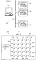
- FIGURE 2 illustrates compound camera system 200 according to a second exemplary embodiment of the present invention.
- Component camera system 200 comprises a plurality of component image sensors and video processor 270.
- each of the component image sensors is a still camera capable of capturing image data for subsequent transfer to video processor 270.
- video processor 270 is capable of processing image data other than video data.
- video processor 270 is capable of processing still image data.
- the component image sensors and video processor 270 may be integrated on one printed circuit board (PCB) 299. In an alternate embodiment of the present invention, the component image sensors and video processor 270 may be integrated on a single integrated circuit (IC) chip 299. Synchronization and communication are accomplished through printed circuit connections 260 on PCB 299 (or IC chip 299).
- PCB printed circuit board
- IC integrated circuit
- the component image sensors are arranged in five rows and five columns to form a 5x5 image sensor array.
- the first row of the array comprises component image sensors 210a, 210b, 210c, 210d and 210e.
- the second row of the array comprises component image sensors 220a, 220b, 220c, 220d and 220e (only image sensor 220e is labeled).
- the third row of the array comprises component image sensors 230a, 230b, 230c, 230d and 230e (only image sensor 230e is labeled).
- the fourth row of the array comprises component image sensors 240a, 240b, 240c, 240d and 240e (only image sensor 240e is labeled).
- the fifth row of the array comprises component image sensor 250a, 250b, 250c, 250d and 250e.
- Component image sensors 210a-e, 220a-e, 230a-e, 240a-e and 250a-e are synchronized with each other and video processor 270.
- Individual image data from component image sensors 210a-e, 220a-e, 230a-e, 240a-e and 250a-e are transmitted to video processor 270, where image processing software takes the image data from component image sensors 210a-e, 220a-e, 230a-e, 240a-e and 250a-e as input and synthesizes an output image following the specifications of a virtual camera, as described below in greater detail.
- FIGURE 3 is an optical arrangement illustrating the operation of compound camera systems 100 and 200 according to the principles of the present invention.
- Processing system 130 (or video processor 270) generates a virtual image I v from input images acquired by the component video cameras in FIGURE 1 (or the component image sensors in FIGURE 2.
- component image sensors 210 and 210b are used to capture image data and video processor 270.
- the following description also applies to alternate embodiments of compound cameras, including the compound camera illustrated in FIGURE 1.
- object 0 double headed arrow
- object plane indicated by a dotted line
- Component image sensor 210a produces image I 1 at focal length f 1 from object O.
- Component image sensor 210b produces image I 2 at focal length f 2 from object O.
- f 1 f 2 .
- the virtual image, I v is synthesized from two input images I 1 and I 2 .
- ⁇ 1 is the angle between the ray sent from (u,v) and the ray sent from (u 1 , v 1 )
- ⁇ 2 is the angle between the ray sent from (u,v) and the ray sent from (u 2 , v 2 ) .
- M 1 and M 2 depend on the common focal length, f, of both component cameras, the virtual focal length, f v , and the depth, z, of the object plane.
- the procedure is substantially the same as above, except that the procedure repeats more times to include all the cameras.
- the steps are as follows:
- Equation 3 can be simplified as:
- Equation 5 maps a point (x,y) on the 2-D plane with depth z to an image pixel (u,v).
- the difference between P and T is that the former is a mapping from 3-D to 2-D, while the latter is from 2-D to 2-D.
- the inverse form of Equation 5 is:
- Equation 6 projects a pixel (u,v) on the image plane back onto the object plane at depth z.
- Video processor 270 first back-projects a virtual pixel (u,v) from I v to the plane at z, resulting in the point (x,y,z), according to the equation:
- video processor 270 forward projects the point (x,y,z) to component image plane I according to the equation:
- the matrix M is called a "warping matrix” because it warps a pixel from the image plane of a first camera to the image plane of another camera. It is apparent that M is a function of the depth, z, and the focal lengths, f and f v , respectively, of the component and virtual cameras.
- three types of matrices are involved: 1) the matrix P maps 3-D to 2-D; 2) the matrix T maps a regular 2-D plane to the image plane; and 3) the matrix M maps the image plane to another image plane.
- the algorithm set forth above may be used to implement auto-focus, depth-of-field, and high-resolution functions in a compound camera without requiring complex and expensive electromechanical equipment.
- FIGURE 4 illustrates the placement of the object plane (or depth plane) at several locations on the body of an object.
- the object is watering bucket 400, which comprises container 405, side handle 410, top handle 415, and spout 420.
- the image of watering bucket 400 is captured by compound camera system 200.
- video processor 270 may place the object plane (or depth plane), z, at numerous locations on the body of watering bucket 400 that are visible to compound camera 200.
- video processor 270 may place the depth plane a point B on the front surface of container 405.
- video processor 270 may place the depth plane at point A on the front of top handle 415 or at point C on the end of spout 420.
- FIGURES 5A and 5B illustrate the effect of moving depth plane, Z, to different depths.
- the depth plane (or object plane) is at depth Z1.
- R v is a virtual light ray
- R 1 and R 2 are two light rays transmitted to two different image sensors 210a and 210b from circular object 500.
- Image sensor 210a sees the point A
- image sensor 210b sees the point B.
- Point A and point B have different colors.
- I v ( R v ) w 1 ⁇ I 1 ( R 1 ) + w 2 ⁇ I 2 ( R 2 ) / w 1 + w 2
- the color of R v is a combination of both colors from point A and point B. This is the source of the blur that may occur in FIGURE 4.
- a second depth plane is added at Z2, as shown in FIGURE 5B.
- points A and B are much closer, their colors are more likely to be similar, resulting in less blur overall. This suggests that using multiple depth planes may help to reduce the blur.
- video processor 270 selects the depth plane that has the least color variance.
- a traditional camera implements the auto-focus function by sliding the image plane and analyzing the resulting images.
- the action of physically sliding the image plane is instead performed by video processor 270, which digitally moves a virtual depth plane in software.
- video processor 270 implements the depth-of-field function by using multiple virtual depth planes that cover the depth range of interest (e.g., from Z1 to Z2). Video processor 270 then integrates all of the potential virtual images into a final image. Video processor 270 generates the final image by selecting from each of the component virtual images groups of pixels that have the least amount of blur. This requires high levels of computation by video processor 270. However, there are no physical parts involved.
- video processor 270 can, at the same time, estimate the depth of scene objects. It is recalled from above that for a virtual pixel (u,v), video processor 270 may select a set of candidate depth positions z 1 , z 2 , ..., z m , in the space.
- video processor 270 sends out a virtual ray.
- the virtual ray intersects with a series of planes whose depth range covers the whole scene of interest.
- video processor 270 retrieves the corresponding input rays and calculates the average color and variance. The color and depth of the intersection with the lowest variance is recorded as that of the current virtual ray.
- a virtual image plus its depth map is formed by video processor 270. The resolution of the depth map depends on the number of planes selected by video processor 270. More depth planes give finer depth maps.
- Video processor 270 also implements a high-resolution function by selecting a virtual camera having a higher density of pixels. Video processor 270 inserts new pixels by "warping" or interpolating pixels from different component cameras.
- a compound camera by definition includes multiple component cameras at different locations and, therefore, different viewing angles. The component cameras see different points on the object. When the component images are combined after compensating their relative positions with respect to the virtual camera, a virtual image of higher resolution than the input ones can be synthesized.
- the resolution enhancement is not linearly related to the number of component cameras. That is to say, N component cameras do not necessarily guarantee a virtual image of resolution N times higher.
Landscapes
- Engineering & Computer Science (AREA)
- Theoretical Computer Science (AREA)
- Multimedia (AREA)
- Physics & Mathematics (AREA)
- Computing Systems (AREA)
- Signal Processing (AREA)
- General Physics & Mathematics (AREA)
- Geometry (AREA)
- Computer Graphics (AREA)
- Health & Medical Sciences (AREA)
- General Health & Medical Sciences (AREA)
- Vascular Medicine (AREA)
- Image Processing (AREA)
- Studio Devices (AREA)
- Testing, Inspecting, Measuring Of Stereoscopic Televisions And Televisions (AREA)
- Stereoscopic And Panoramic Photography (AREA)
- Studio Circuits (AREA)
Applications Claiming Priority (2)
| Application Number | Priority Date | Filing Date | Title |
|---|---|---|---|
| US10/407,490 US7425984B2 (en) | 2003-04-04 | 2003-04-04 | Compound camera and methods for implementing auto-focus, depth-of-field and high-resolution functions |
| US407490 | 2003-04-04 |
Publications (3)
| Publication Number | Publication Date |
|---|---|
| EP1465111A2 true EP1465111A2 (fr) | 2004-10-06 |
| EP1465111A3 EP1465111A3 (fr) | 2005-04-06 |
| EP1465111B1 EP1465111B1 (fr) | 2009-09-02 |
Family
ID=32850666
Family Applications (1)
| Application Number | Title | Priority Date | Filing Date |
|---|---|---|---|
| EP04252003A Expired - Lifetime EP1465111B1 (fr) | 2003-04-04 | 2004-04-02 | Système et méthode de photo pour produire une image avec un profondeur-de-champ agrandi |
Country Status (4)
| Country | Link |
|---|---|
| US (2) | US7425984B2 (fr) |
| EP (1) | EP1465111B1 (fr) |
| JP (1) | JP2004312745A (fr) |
| DE (1) | DE602004022889D1 (fr) |
Families Citing this family (81)
| Publication number | Priority date | Publication date | Assignee | Title |
|---|---|---|---|---|
| US7268804B2 (en) | 2003-04-04 | 2007-09-11 | Stmicroelectronics, Inc. | Compound camera and method for synthesizing a virtual image from multiple input images |
| US8553113B2 (en) * | 2003-08-20 | 2013-10-08 | At&T Intellectual Property I, L.P. | Digital image capturing system and method |
| US20060268360A1 (en) * | 2005-05-12 | 2006-11-30 | Jones Peter W J | Methods of creating a virtual window |
| US8446509B2 (en) * | 2006-08-09 | 2013-05-21 | Tenebraex Corporation | Methods of creating a virtual window |
| US8791984B2 (en) * | 2007-11-16 | 2014-07-29 | Scallop Imaging, Llc | Digital security camera |
| US8564640B2 (en) * | 2007-11-16 | 2013-10-22 | Tenebraex Corporation | Systems and methods of creating a virtual window |
| US20090290033A1 (en) * | 2007-11-16 | 2009-11-26 | Tenebraex Corporation | Systems and methods of creating a virtual window |
| US8280194B2 (en) * | 2008-04-29 | 2012-10-02 | Sony Corporation | Reduced hardware implementation for a two-picture depth map algorithm |
| US11792538B2 (en) | 2008-05-20 | 2023-10-17 | Adeia Imaging Llc | Capturing and processing of images including occlusions focused on an image sensor by a lens stack array |
| US8866920B2 (en) | 2008-05-20 | 2014-10-21 | Pelican Imaging Corporation | Capturing and processing of images using monolithic camera array with heterogeneous imagers |
| EP3328048B1 (fr) | 2008-05-20 | 2021-04-21 | FotoNation Limited | Capture et traitement d'images au moyen d'un réseau de caméras monolithiques avec des imageurs hétérogènes |
| CN101673395B (zh) * | 2008-09-10 | 2012-09-05 | 华为终端有限公司 | 图像拼接方法及装置 |
| US8194995B2 (en) * | 2008-09-30 | 2012-06-05 | Sony Corporation | Fast camera auto-focus |
| US8553093B2 (en) | 2008-09-30 | 2013-10-08 | Sony Corporation | Method and apparatus for super-resolution imaging using digital imaging devices |
| US8436909B2 (en) | 2008-10-21 | 2013-05-07 | Stmicroelectronics S.R.L. | Compound camera sensor and related method of processing digital images |
| WO2011037964A1 (fr) * | 2009-09-22 | 2011-03-31 | Tenebraex Corporation | Systèmes et procédés de correction d'image dans un système multicapteur |
| EP2502115A4 (fr) | 2009-11-20 | 2013-11-06 | Pelican Imaging Corp | Capture et traitement d'images au moyen d'un réseau de caméras monolithique équipé d'imageurs hétérogènes |
| US8335390B2 (en) * | 2010-03-22 | 2012-12-18 | Sony Corporation | Blur function modeling for depth of field rendering |
| CN103004180A (zh) | 2010-05-12 | 2013-03-27 | 派力肯影像公司 | 成像器阵列和阵列照相机的架构 |
| EP2410377A1 (fr) | 2010-07-20 | 2012-01-25 | Research In Motion Limited | Procédé pour diminuer la profondeur de champ d'un appareil photo doté d'une ouverture fixe |
| US8878950B2 (en) | 2010-12-14 | 2014-11-04 | Pelican Imaging Corporation | Systems and methods for synthesizing high resolution images using super-resolution processes |
| US8305456B1 (en) | 2011-05-11 | 2012-11-06 | Pelican Imaging Corporation | Systems and methods for transmitting and receiving array camera image data |
| US20130265459A1 (en) | 2011-06-28 | 2013-10-10 | Pelican Imaging Corporation | Optical arrangements for use with an array camera |
| US8928737B2 (en) * | 2011-07-26 | 2015-01-06 | Indiana University Research And Technology Corp. | System and method for three dimensional imaging |
| US20140225991A1 (en) * | 2011-09-02 | 2014-08-14 | Htc Corporation | Image capturing apparatus and method for obatining depth information of field thereof |
| US20130057655A1 (en) * | 2011-09-02 | 2013-03-07 | Wen-Yueh Su | Image processing system and automatic focusing method |
| WO2013043751A1 (fr) | 2011-09-19 | 2013-03-28 | Pelican Imaging Corporation | Systèmes et procédés permettant de commander le crénelage des images capturées par une caméra disposée en réseau destinée à être utilisée dans le traitement à super-résolution à l'aide d'ouvertures de pixel |
| CN104081414B (zh) | 2011-09-28 | 2017-08-01 | Fotonation开曼有限公司 | 用于编码和解码光场图像文件的系统及方法 |
| US9412206B2 (en) | 2012-02-21 | 2016-08-09 | Pelican Imaging Corporation | Systems and methods for the manipulation of captured light field image data |
| US9210392B2 (en) | 2012-05-01 | 2015-12-08 | Pelican Imaging Coporation | Camera modules patterned with pi filter groups |
| EP2873028A4 (fr) | 2012-06-28 | 2016-05-25 | Pelican Imaging Corp | Systèmes et procédés pour détecter des réseaux de caméras, des réseaux optiques et des capteurs défectueux |
| US20140002674A1 (en) | 2012-06-30 | 2014-01-02 | Pelican Imaging Corporation | Systems and Methods for Manufacturing Camera Modules Using Active Alignment of Lens Stack Arrays and Sensors |
| CN107346061B (zh) | 2012-08-21 | 2020-04-24 | 快图有限公司 | 用于使用阵列照相机捕捉的图像中的视差检测和校正的系统和方法 |
| EP2888698A4 (fr) | 2012-08-23 | 2016-06-29 | Pelican Imaging Corp | Estimation de mouvement en haute résolution basée sur des éléments à partir d'images en basse résolution capturées à l'aide d'une source matricielle |
| WO2014052974A2 (fr) * | 2012-09-28 | 2014-04-03 | Pelican Imaging Corporation | Création d'images à partir de champs de lumière en utilisant des points de vue virtuels |
| US9143711B2 (en) | 2012-11-13 | 2015-09-22 | Pelican Imaging Corporation | Systems and methods for array camera focal plane control |
| KR101358042B1 (ko) | 2013-01-31 | 2014-02-10 | 주식회사 나무가 | 개체차 조정장치 |
| US9462164B2 (en) | 2013-02-21 | 2016-10-04 | Pelican Imaging Corporation | Systems and methods for generating compressed light field representation data using captured light fields, array geometry, and parallax information |
| US9253380B2 (en) | 2013-02-24 | 2016-02-02 | Pelican Imaging Corporation | Thin form factor computational array cameras and modular array cameras |
| US9774789B2 (en) | 2013-03-08 | 2017-09-26 | Fotonation Cayman Limited | Systems and methods for high dynamic range imaging using array cameras |
| US8866912B2 (en) | 2013-03-10 | 2014-10-21 | Pelican Imaging Corporation | System and methods for calibration of an array camera using a single captured image |
| US9106784B2 (en) | 2013-03-13 | 2015-08-11 | Pelican Imaging Corporation | Systems and methods for controlling aliasing in images captured by an array camera for use in super-resolution processing |
| US9124831B2 (en) | 2013-03-13 | 2015-09-01 | Pelican Imaging Corporation | System and methods for calibration of an array camera |
| US9519972B2 (en) | 2013-03-13 | 2016-12-13 | Kip Peli P1 Lp | Systems and methods for synthesizing images from image data captured by an array camera using restricted depth of field depth maps in which depth estimation precision varies |
| US9888194B2 (en) | 2013-03-13 | 2018-02-06 | Fotonation Cayman Limited | Array camera architecture implementing quantum film image sensors |
| WO2014159779A1 (fr) | 2013-03-14 | 2014-10-02 | Pelican Imaging Corporation | Systèmes et procédés de réduction du flou cinétique dans des images ou une vidéo par luminosité ultra faible avec des caméras en réseau |
| WO2014153098A1 (fr) | 2013-03-14 | 2014-09-25 | Pelican Imaging Corporation | Normalisation photométrique dans des caméras matricielles |
| US9497429B2 (en) | 2013-03-15 | 2016-11-15 | Pelican Imaging Corporation | Extended color processing on pelican array cameras |
| EP4604059A3 (fr) | 2013-03-15 | 2025-09-17 | Adeia Imaging LLC | Systeme und verfahren zur stereobildgebung mit kameraarrays |
| WO2014150856A1 (fr) | 2013-03-15 | 2014-09-25 | Pelican Imaging Corporation | Appareil de prise de vue matriciel mettant en œuvre des filtres colorés à points quantiques |
| US10122993B2 (en) | 2013-03-15 | 2018-11-06 | Fotonation Limited | Autofocus system for a conventional camera that uses depth information from an array camera |
| US9445003B1 (en) | 2013-03-15 | 2016-09-13 | Pelican Imaging Corporation | Systems and methods for synthesizing high resolution images using image deconvolution based on motion and depth information |
| JP6100089B2 (ja) * | 2013-05-17 | 2017-03-22 | キヤノン株式会社 | 画像処理装置、画像処理方法およびプログラム |
| WO2015048694A2 (fr) | 2013-09-27 | 2015-04-02 | Pelican Imaging Corporation | Systèmes et procédés destinés à la correction de la distorsion de la perspective utilisant la profondeur |
| US9426343B2 (en) | 2013-11-07 | 2016-08-23 | Pelican Imaging Corporation | Array cameras incorporating independently aligned lens stacks |
| US10119808B2 (en) | 2013-11-18 | 2018-11-06 | Fotonation Limited | Systems and methods for estimating depth from projected texture using camera arrays |
| EP3075140B1 (fr) | 2013-11-26 | 2018-06-13 | FotoNation Cayman Limited | Configurations de caméras en réseau comprenant de multiples caméras en réseau constitutives |
| US10089740B2 (en) | 2014-03-07 | 2018-10-02 | Fotonation Limited | System and methods for depth regularization and semiautomatic interactive matting using RGB-D images |
| US9521319B2 (en) | 2014-06-18 | 2016-12-13 | Pelican Imaging Corporation | Array cameras and array camera modules including spectral filters disposed outside of a constituent image sensor |
| CN113256730B (zh) | 2014-09-29 | 2023-09-05 | 快图有限公司 | 用于阵列相机的动态校准的系统和方法 |
| US9942474B2 (en) | 2015-04-17 | 2018-04-10 | Fotonation Cayman Limited | Systems and methods for performing high speed video capture and depth estimation using array cameras |
| CN107346531A (zh) * | 2016-05-05 | 2017-11-14 | 中兴通讯股份有限公司 | 一种图像优化方法、装置及终端 |
| US10482618B2 (en) | 2017-08-21 | 2019-11-19 | Fotonation Limited | Systems and methods for hybrid depth regularization |
| US10721419B2 (en) * | 2017-11-30 | 2020-07-21 | International Business Machines Corporation | Ortho-selfie distortion correction using multiple image sensors to synthesize a virtual image |
| WO2021055585A1 (fr) | 2019-09-17 | 2021-03-25 | Boston Polarimetrics, Inc. | Systèmes et procédés de modélisation de surface utilisant des repères de polarisation |
| WO2021071995A1 (fr) | 2019-10-07 | 2021-04-15 | Boston Polarimetrics, Inc. | Systèmes et procédés de détection de normales à une surface à l'aide d'une polarisation |
| EP4066001B1 (fr) | 2019-11-30 | 2026-03-04 | Intrinsic Innovation LLC | Systèmes et procédés de segmentation d'objets transparents au moyen de files d'attentes de polarisation |
| JP7462769B2 (ja) | 2020-01-29 | 2024-04-05 | イントリンジック イノベーション エルエルシー | 物体の姿勢の検出および測定システムを特徴付けるためのシステムおよび方法 |
| US11797863B2 (en) | 2020-01-30 | 2023-10-24 | Intrinsic Innovation Llc | Systems and methods for synthesizing data for training statistical models on different imaging modalities including polarized images |
| WO2021243088A1 (fr) | 2020-05-27 | 2021-12-02 | Boston Polarimetrics, Inc. | Systèmes optiques de polarisation à ouvertures multiples utilisant des diviseurs de faisceau |
| US12020455B2 (en) | 2021-03-10 | 2024-06-25 | Intrinsic Innovation Llc | Systems and methods for high dynamic range image reconstruction |
| US12069227B2 (en) | 2021-03-10 | 2024-08-20 | Intrinsic Innovation Llc | Multi-modal and multi-spectral stereo camera arrays |
| US11290658B1 (en) | 2021-04-15 | 2022-03-29 | Boston Polarimetrics, Inc. | Systems and methods for camera exposure control |
| US11954886B2 (en) | 2021-04-15 | 2024-04-09 | Intrinsic Innovation Llc | Systems and methods for six-degree of freedom pose estimation of deformable objects |
| US12067746B2 (en) | 2021-05-07 | 2024-08-20 | Intrinsic Innovation Llc | Systems and methods for using computer vision to pick up small objects |
| US12175741B2 (en) | 2021-06-22 | 2024-12-24 | Intrinsic Innovation Llc | Systems and methods for a vision guided end effector |
| US12340538B2 (en) | 2021-06-25 | 2025-06-24 | Intrinsic Innovation Llc | Systems and methods for generating and using visual datasets for training computer vision models |
| US12172310B2 (en) | 2021-06-29 | 2024-12-24 | Intrinsic Innovation Llc | Systems and methods for picking objects using 3-D geometry and segmentation |
| US11689813B2 (en) | 2021-07-01 | 2023-06-27 | Intrinsic Innovation Llc | Systems and methods for high dynamic range imaging using crossed polarizers |
| US12293535B2 (en) | 2021-08-03 | 2025-05-06 | Intrinsic Innovation Llc | Systems and methods for training pose estimators in computer vision |
| US12561938B2 (en) * | 2024-03-25 | 2026-02-24 | Nvidia Corporation | Efficient pixel density measurement of stitched images |
Citations (2)
| Publication number | Priority date | Publication date | Assignee | Title |
|---|---|---|---|---|
| US4404594A (en) | 1981-11-02 | 1983-09-13 | Itek Corporation | Imaging system with enlarged depth of field |
| US20040196391A1 (en) | 2003-04-04 | 2004-10-07 | Stmicroelectronics, Inc. | Compound camera and method for synthesizing a virtural image from multiple input images |
Family Cites Families (11)
| Publication number | Priority date | Publication date | Assignee | Title |
|---|---|---|---|---|
| JP3745117B2 (ja) * | 1998-05-08 | 2006-02-15 | キヤノン株式会社 | 画像処理装置及び画像処理方法 |
| US6469710B1 (en) * | 1998-09-25 | 2002-10-22 | Microsoft Corporation | Inverse texture mapping using weighted pyramid blending |
| US6201899B1 (en) * | 1998-10-09 | 2001-03-13 | Sarnoff Corporation | Method and apparatus for extended depth of field imaging |
| CA2316611A1 (fr) * | 1999-08-31 | 2001-02-28 | Nintendo Co. Ltd. | Methode et appareil pour produire des effets de flou selon la profondeur dans un systeme videographique 3d |
| US7085409B2 (en) * | 2000-10-18 | 2006-08-01 | Sarnoff Corporation | Method and apparatus for synthesizing new video and/or still imagery from a collection of real video and/or still imagery |
| US6990681B2 (en) * | 2001-08-09 | 2006-01-24 | Sony Corporation | Enhancing broadcast of an event with synthetic scene using a depth map |
| US7003136B1 (en) * | 2002-04-26 | 2006-02-21 | Hewlett-Packard Development Company, L.P. | Plan-view projections of depth image data for object tracking |
| US7006709B2 (en) * | 2002-06-15 | 2006-02-28 | Microsoft Corporation | System and method deghosting mosaics using multiperspective plane sweep |
| US7084904B2 (en) * | 2002-09-30 | 2006-08-01 | Microsoft Corporation | Foveated wide-angle imaging system and method for capturing and viewing wide-angle images in real time |
| US6975329B2 (en) * | 2002-12-09 | 2005-12-13 | Nvidia Corporation | Depth-of-field effects using texture lookup |
| US20030146922A1 (en) * | 2002-12-20 | 2003-08-07 | Nassir Navab | System and method for diminished reality |
-
2003
- 2003-04-04 US US10/407,490 patent/US7425984B2/en not_active Expired - Fee Related
-
2004
- 2004-04-02 EP EP04252003A patent/EP1465111B1/fr not_active Expired - Lifetime
- 2004-04-02 DE DE602004022889T patent/DE602004022889D1/de not_active Expired - Fee Related
- 2004-04-05 JP JP2004110671A patent/JP2004312745A/ja active Pending
-
2007
- 2007-12-20 US US12/004,452 patent/US8264541B2/en active Active
Patent Citations (2)
| Publication number | Priority date | Publication date | Assignee | Title |
|---|---|---|---|---|
| US4404594A (en) | 1981-11-02 | 1983-09-13 | Itek Corporation | Imaging system with enlarged depth of field |
| US20040196391A1 (en) | 2003-04-04 | 2004-10-07 | Stmicroelectronics, Inc. | Compound camera and method for synthesizing a virtural image from multiple input images |
Non-Patent Citations (2)
| Title |
|---|
| M. LEVOY; P. HANRAHAN: "Light Field Rendering", PROCEEDINGS OF THE ACM SIGGRAPH 96, 1996, pages 31 - 42 |
| OLIVIER FAUGERAS: "Three Dimensional Computer Visions - A Geometric Viewpoint", THE MIT PRESS, 1996 |
Also Published As
| Publication number | Publication date |
|---|---|
| DE602004022889D1 (de) | 2009-10-15 |
| EP1465111B1 (fr) | 2009-09-02 |
| US20080198220A1 (en) | 2008-08-21 |
| JP2004312745A (ja) | 2004-11-04 |
| US20040196379A1 (en) | 2004-10-07 |
| US8264541B2 (en) | 2012-09-11 |
| US7425984B2 (en) | 2008-09-16 |
| EP1465111A3 (fr) | 2005-04-06 |
Similar Documents
| Publication | Publication Date | Title |
|---|---|---|
| EP1465111B1 (fr) | Système et méthode de photo pour produire une image avec un profondeur-de-champ agrandi | |
| EP3057317B1 (fr) | Caméra plénoptique | |
| US6570566B1 (en) | Image processing apparatus, image processing method, and program providing medium | |
| EP2353298B1 (fr) | Procédé et système servant à produire des contenus visuels 3d à vues multiples | |
| US8290358B1 (en) | Methods and apparatus for light-field imaging | |
| CN114049434B (zh) | 一种基于全卷积神经网络的3d建模方法及系统 | |
| EP1580523A1 (fr) | Procede et dispositif permettant de mesurer une forme tridimensionnelle | |
| US9063323B2 (en) | Super light-field lens and image processing methods | |
| CN110517211B (zh) | 一种基于梯度域映射的图像融合方法 | |
| WO2003083773A2 (fr) | Procede et systeme d'imagerie | |
| EP0707287B1 (fr) | Appareil et procédé de traitement de données d'image | |
| WO2015190616A1 (fr) | Capteur d'images pour estimation de profondeur | |
| EP1079637A3 (fr) | Appareil de prise de vues en couleurs | |
| US10529057B2 (en) | Image processing apparatus and image processing method | |
| JP7378219B2 (ja) | 撮像装置、画像処理装置、制御方法、及びプログラム | |
| JP3990271B2 (ja) | 簡易ステレオ画像入力装置、方法、プログラム、および記録媒体 | |
| CA2540538C (fr) | Imagerie stereoscopique | |
| EP1465112A2 (fr) | Caméra composite et procédé de synthèse d'une image virtuelle à partir de plusieurs images d'entrée | |
| Matsui et al. | Soccer image sequence computed by a virtual camera | |
| US10341546B2 (en) | Image processing apparatus and image processing method | |
| Ichimaru et al. | Unified underwater structure-from-motion | |
| US10726581B2 (en) | System and method for scene-space video processing | |
| WO2022192015A1 (fr) | Systèmes et procédés de reconstruction d'image à plage dynamique élevée | |
| KR20220170090A (ko) | 멀티-뷰 이미지에서 노이즈 감소를 위한 장치 및 방법 | |
| WO2007007924A1 (fr) | Procede d'etalonnage de distorsion d'image a vues multiples |
Legal Events
| Date | Code | Title | Description |
|---|---|---|---|
| PUAI | Public reference made under article 153(3) epc to a published international application that has entered the european phase |
Free format text: ORIGINAL CODE: 0009012 |
|
| AK | Designated contracting states |
Kind code of ref document: A2 Designated state(s): AT BE BG CH CY CZ DE DK EE ES FI FR GB GR HU IE IT LI LU MC NL PL PT RO SE SI SK TR |
|
| AX | Request for extension of the european patent |
Extension state: AL HR LT LV MK |
|
| PUAL | Search report despatched |
Free format text: ORIGINAL CODE: 0009013 |
|
| AK | Designated contracting states |
Kind code of ref document: A3 Designated state(s): AT BE BG CH CY CZ DE DK EE ES FI FR GB GR HU IE IT LI LU MC NL PL PT RO SE SI SK TR |
|
| AX | Request for extension of the european patent |
Extension state: AL HR LT LV MK |
|
| 17P | Request for examination filed |
Effective date: 20050916 |
|
| AKX | Designation fees paid |
Designated state(s): DE FR GB IT |
|
| RIN1 | Information on inventor provided before grant (corrected) |
Inventor name: MCGUINESS, PETER Inventor name: Q CHEN, GEORGE Inventor name: HONG, LI |
|
| 17Q | First examination report despatched |
Effective date: 20070803 |
|
| GRAP | Despatch of communication of intention to grant a patent |
Free format text: ORIGINAL CODE: EPIDOSNIGR1 |
|
| GRAS | Grant fee paid |
Free format text: ORIGINAL CODE: EPIDOSNIGR3 |
|
| GRAA | (expected) grant |
Free format text: ORIGINAL CODE: 0009210 |
|
| AK | Designated contracting states |
Kind code of ref document: B1 Designated state(s): DE FR GB IT |
|
| REF | Corresponds to: |
Ref document number: 602004022889 Country of ref document: DE Date of ref document: 20091015 Kind code of ref document: P |
|
| PLBE | No opposition filed within time limit |
Free format text: ORIGINAL CODE: 0009261 |
|
| STAA | Information on the status of an ep patent application or granted ep patent |
Free format text: STATUS: NO OPPOSITION FILED WITHIN TIME LIMIT |
|
| 26N | No opposition filed |
Effective date: 20100603 |
|
| PG25 | Lapsed in a contracting state [announced via postgrant information from national office to epo] |
Ref country code: DE Free format text: LAPSE BECAUSE OF NON-PAYMENT OF DUE FEES Effective date: 20101103 |
|
| PG25 | Lapsed in a contracting state [announced via postgrant information from national office to epo] |
Ref country code: IT Free format text: LAPSE BECAUSE OF FAILURE TO SUBMIT A TRANSLATION OF THE DESCRIPTION OR TO PAY THE FEE WITHIN THE PRESCRIBED TIME-LIMIT Effective date: 20090902 |
|
| REG | Reference to a national code |
Ref country code: FR Ref legal event code: PLFP Year of fee payment: 13 |
|
| REG | Reference to a national code |
Ref country code: FR Ref legal event code: PLFP Year of fee payment: 14 |
|
| REG | Reference to a national code |
Ref country code: FR Ref legal event code: PLFP Year of fee payment: 15 |
|
| PGFP | Annual fee paid to national office [announced via postgrant information from national office to epo] |
Ref country code: FR Payment date: 20230321 Year of fee payment: 20 |
|
| PGFP | Annual fee paid to national office [announced via postgrant information from national office to epo] |
Ref country code: GB Payment date: 20230321 Year of fee payment: 20 |
|
| REG | Reference to a national code |
Ref country code: GB Ref legal event code: PE20 Expiry date: 20240401 |
|
| PG25 | Lapsed in a contracting state [announced via postgrant information from national office to epo] |
Ref country code: GB Free format text: LAPSE BECAUSE OF EXPIRATION OF PROTECTION Effective date: 20240401 |