EP1465112A2 - Zusammengesetzte Kamera und Verfahren zur Synthese eines virtuellen Bildes aus mehreren Eingangsbildern - Google Patents
Zusammengesetzte Kamera und Verfahren zur Synthese eines virtuellen Bildes aus mehreren Eingangsbildern Download PDFInfo
- Publication number
- EP1465112A2 EP1465112A2 EP04252002A EP04252002A EP1465112A2 EP 1465112 A2 EP1465112 A2 EP 1465112A2 EP 04252002 A EP04252002 A EP 04252002A EP 04252002 A EP04252002 A EP 04252002A EP 1465112 A2 EP1465112 A2 EP 1465112A2
- Authority
- EP
- European Patent Office
- Prior art keywords
- data
- image
- pixel data
- plane
- virtual
- Prior art date
- Legal status (The legal status is an assumption and is not a legal conclusion. Google has not performed a legal analysis and makes no representation as to the accuracy of the status listed.)
- Withdrawn
Links
Images

Classifications
-
- G—PHYSICS
- G06—COMPUTING OR CALCULATING; COUNTING
- G06T—IMAGE DATA PROCESSING OR GENERATION, IN GENERAL
- G06T15/00—Three-dimensional [3D] image rendering
- G06T15/10—Geometric effects
- G06T15/20—Perspective computation
-
- G—PHYSICS
- G06—COMPUTING OR CALCULATING; COUNTING
- G06T—IMAGE DATA PROCESSING OR GENERATION, IN GENERAL
- G06T5/00—Image enhancement or restoration
- G06T5/50—Image enhancement or restoration using two or more images, e.g. averaging or subtraction
-
- G—PHYSICS
- G06—COMPUTING OR CALCULATING; COUNTING
- G06T—IMAGE DATA PROCESSING OR GENERATION, IN GENERAL
- G06T5/00—Image enhancement or restoration
- G06T5/73—Deblurring; Sharpening
-
- G—PHYSICS
- G06—COMPUTING OR CALCULATING; COUNTING
- G06V—IMAGE OR VIDEO RECOGNITION OR UNDERSTANDING
- G06V10/00—Arrangements for image or video recognition or understanding
- G06V10/10—Image acquisition
- G06V10/12—Details of acquisition arrangements; Constructional details thereof
- G06V10/14—Optical characteristics of the device performing the acquisition or on the illumination arrangements
- G06V10/147—Details of sensors, e.g. sensor lenses
-
- H—ELECTRICITY
- H04—ELECTRIC COMMUNICATION TECHNIQUE
- H04N—PICTORIAL COMMUNICATION, e.g. TELEVISION
- H04N23/00—Cameras or camera modules comprising electronic image sensors; Control thereof
- H04N23/45—Cameras or camera modules comprising electronic image sensors; Control thereof for generating image signals from two or more image sensors being of different type or operating in different modes, e.g. with a CMOS sensor for moving images in combination with a charge-coupled device [CCD] for still images
-
- H—ELECTRICITY
- H04—ELECTRIC COMMUNICATION TECHNIQUE
- H04N—PICTORIAL COMMUNICATION, e.g. TELEVISION
- H04N23/00—Cameras or camera modules comprising electronic image sensors; Control thereof
- H04N23/80—Camera processing pipelines; Components thereof
-
- H—ELECTRICITY
- H04—ELECTRIC COMMUNICATION TECHNIQUE
- H04N—PICTORIAL COMMUNICATION, e.g. TELEVISION
- H04N23/00—Cameras or camera modules comprising electronic image sensors; Control thereof
- H04N23/95—Computational photography systems, e.g. light-field imaging systems
- H04N23/951—Computational photography systems, e.g. light-field imaging systems by using two or more images to influence resolution, frame rate or aspect ratio
-
- H—ELECTRICITY
- H04—ELECTRIC COMMUNICATION TECHNIQUE
- H04N—PICTORIAL COMMUNICATION, e.g. TELEVISION
- H04N23/00—Cameras or camera modules comprising electronic image sensors; Control thereof
- H04N23/95—Computational photography systems, e.g. light-field imaging systems
- H04N23/957—Light-field or plenoptic cameras or camera modules
-
- H—ELECTRICITY
- H04—ELECTRIC COMMUNICATION TECHNIQUE
- H04N—PICTORIAL COMMUNICATION, e.g. TELEVISION
- H04N23/00—Cameras or camera modules comprising electronic image sensors; Control thereof
- H04N23/95—Computational photography systems, e.g. light-field imaging systems
- H04N23/958—Computational photography systems, e.g. light-field imaging systems for extended depth of field imaging
-
- G—PHYSICS
- G06—COMPUTING OR CALCULATING; COUNTING
- G06T—IMAGE DATA PROCESSING OR GENERATION, IN GENERAL
- G06T2207/00—Indexing scheme for image analysis or image enhancement
- G06T2207/10—Image acquisition modality
- G06T2207/10028—Range image; Depth image; 3D point clouds
Definitions
- the present invention is related to those disclosed in United States Patent Application Serial No. [Attorney Docket No. 02-LJ-080], filed concurrently herewith, entitled “Compound Camera And Methods For Implementing Auto-Focus, Depth-Of-Field And High-Resolution Functions".
- Application Serial No. [Attorney Docket No. 02-LJ-080] is commonly assigned to the assignee of the present invention.
- the disclosures of this related patent application is hereby incorporated by reference for all purposes as if fully set forth herein.
- the present invention is generally directed to image processing devices and, in particular, to a compound camera that generates virtual images from a plurality of input images captured by the compound camera.
- a compound camera consists of a set of component cameras, a data processor and image processing software that runs on the data processor.
- the component cameras may be synchronized through wired or wireless electronic signals. Individual images from the component cameras are transmitted to the data processor through wired or wireless connections.
- the image processing software takes images from the component cameras as input and synthesizes an output image following the specifications of a virtual camera.
- a conventional compound camera may be implemented in a number of ways.
- a compound camera may comprise a number of synchronized regular video cameras and a separate microprocessor connected to the video component cameras.
- a plurality of component image sensors and a microprocessor may be integrated on one substrate, such as a printed circuit board (PCB) or a hybrid substrate. Synchronization and communication are accomplished through the printed circuit connections on the substrate.
- the component image sensors and the microprocessor are very small and are integrated on a single silicon chip.
- the physical model of a camera consists of a shutter, a lens and an image plane. The shutter has an opening called an aperture that lets light enter into the camera. A bundle of light rays coming out of a point on an object surface enters through the aperture, is refracted by the lens, and is gathered and focused on the image plane, where the color of the object point is recorded.
- depth-of-field For a certain aperture size, there is a range of depth within which the image is sharp. This is called the "depth-of-field" and it is inversely proportional to the aperture size.
- the image plane slides back and forth to search for the best overall image within the range of the depth-of-field. Normally, large depth-of-field coverage is desired. This, in turn, requires high sensitivity from the sensor because the aperture size is proportionally small.
- the prior art conventional compound camera image processing systems mainly focus on two areas.
- the common practice is to first recover the 3-dimensional geometry of the objects in the scene. This is called structure-from-motion.
- the input images are transferred to the virtual camera via the recovered geometry.
- a good reference is Olivier Faugeras, "Three Dimensional Computer Visions - A Geometric Viewpoint," The MIT Press, 1996.
- the disclosure of the Faugeras text is hereby incorporated by reference for all purposes as if fully set forth herein.
- the problem of this approach is that the reconstructed geometry normally is not very accurate, especially on object surfaces that lack color texture. This result in visible artifacts in the synthesized image.
- the light field approach can be thought of as using only one depth plane.
- a good reference for the light field approach is M. Levoy and P. Hanrahan, "Light Field Rendering," Proceedings of the ACM SIGGRAPH 96", pp. 31-42, 1996.
- the disclosures of the Levoy and Hanrahan text is hereby incorporated by reference for all purposes as if fully set forth herein.
- the component cameras in order to deal with blur, the component cameras must be densely placed. Densely placed cameras normally imply a large number of cameras. A large number of cameras, in turn, produce a large amount of data to be processed. This vastly increases the cost and complexity of the image processing system.
- a primary object of the present invention to provide a compound camera system comprising: 1) a plurality of component cameras capable of generating image data of an object; and 2) a data processor capable of receiving image data from a plurality of component cameras and generating a virtual image.
- the data processor then projects the point data (x,y,z) to generate first pixel data (u 1 ,v 1 ) located at the image plane of the first image data. Afterwards, the data processor projects the same point data (x,y,z) to generate second pixel data (u 2 ,v 2 ) located at the image plane of the second image data.
- the data processor generates the virtual image by combining the color I1 of the first pixel data (u 1 ,v 1 ) and the color I2 of the second pixel data (u 2 ,v 2 ).
- the data processor combines the color I1 of the first pixel data (u 1 ,v 1 ) and the color I2 of the second pixel data (u 2 , v 2 ) by multiplying the first color I1 by a first weighting factor w1 to form a first product, multiplying the second color I2 by a second weighting factor w2 to form a second product, adding the first and second products, and finally dividing the summation of products by the summation of w1 and w2.
- the data processor projects the virtual pixel data (u,v) to generate the point data (x,y,z) using a inverse Plane Projection Matrix and projects the point data (x,y,z) to generate the first virtual pixel data (u 1 ,v 1 ) using a first Plane Projection Matrix.
- the data processor projects the same point data (x,y,z) to generate the second pixel data (u 2 ,v 2 ) using a second Plane Projection Matrix.
- FIGURES 1 through 5 discussed below, and the various embodiments used to describe the principles of the present invention in this patent document are by way of illustration only and should not be construed in any way to limit the scope of the invention. Those skilled in the art will understand that the principles of the present invention may be implemented in any suitably arranged image processing system.
- FIGURES 1-5 are not drawn to scale. Those skilled in the art will recognize that items in FIGURES 1-5 are drawn to show their relative positions in order to simplify the explanation of the operation of the present invention.
- FIGURE 1 illustrates compound camera system 100 according to a first exemplary embodiment of the present invention.
- Compound camera system 100 comprises N component video cameras 110, including exemplary component video cameras 110a, 110b, and 110c, and processing system 130.
- Component video cameras 110a, 110b, and 110c are arbitrarily labeled Video Camera 1, Video Camera 2, and Video Camera N, respectively.
- Processing system 130 and the N component video cameras 110 communicate via communication link 120.
- Communication link 120 may be a wired link, such as a network connection, or a wireless link.
- processing system 130 may be a personal computer (PC), a workstation, or a similar system.
- Component video cameras 110 are synchronized with each other and processing system 130. Individual image data from component video cameras 110 are transmitted to processing system 130, where image processing software takes the image data from component video cameras 110 as input and synthesizes an output image following the specifications of a virtual camera, as described below in greater detail.
- component video cameras 110 be actual video cameras. Those skilled in the art will understand that each component camera 110 may also be a still camera that captures image data for subsequent transfer to processing system 130.
- FIGURE 2 illustrates compound camera system 200 according to a second exemplary embodiment of the present invention.
- Component camera system 200 comprises a plurality of component image sensors and video processor 270.
- each of the component image sensors is a still camera capable of capturing image data for subsequent transfer to video processor 270.
- video processor 270 is capable of processing image data other than video data.
- video processor 270 is capable of processing still image data.
- the component image sensors and video processor 270 may be integrated on one printed circuit board (PCB) 299. In an alternate embodiment of the present invention, the component image sensors and video processor 270 may be integrated on a single integrated circuit (IC) chip 299. Synchronization and communication are accomplished through printed circuit connections 260 on PCB 299 (or IC chip 299).
- PCB printed circuit board
- IC integrated circuit
- the component image sensors are arranged in five rows and five columns to form a 5x5 image sensor array.
- the first row of the array comprises component image sensors 210a, 210b, 210c, 210d and 210e.
- the second row of the array comprises component image sensors 220a, 220b, 220c, 220d and 220e (only image sensor 220e is labeled).
- the third row of the array comprises component image sensors 230a, 230b, 230c, 230d and 230e (only image sensor 230e is labeled).
- the fourth row of the array comprises component image sensors 240a, 240b, 240c, 240d and 240e (only image sensor 240e is labeled).
- the fifth row of the array comprises component image sensor 250a, 250b, 250c, 250d and 250e.
- Component image sensors 210a-e, 220a-e, 230a-e, 240a-e and 250a-e are synchronized with each other and video processor 270.
- Individual image data from component image sensors 210a-e, 220a-e, 230a-e, 240a-e and 250a-e are transmitted to video processor 270, where image processing software takes the image data from component image sensors 210a-e, 220a-e, 230a-e, 240a-e and 250a-e as input and synthesizes an output image following the specifications of a virtual camera, as described below in greater detail.
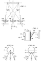
- FIGURE 3 is an optical arrangement illustrating the operation of compound camera systems 100 and 200 according to the principles of the present invention.
- Processing system 130 (or video processor 270) generates a virtual image I v from input images acquired by the component video cameras in FIGURE 1 (or the component image sensors in FIGURE 2.
- component image sensors 210 and 210b are used to capture image data and video processor 270.
- the following description also applies to alternate embodiments of compound cameras, including the compound camera illustrated in FIGURE 1.
- object O (double headed arrow) lies in the object plane (indicated by a dotted line).
- Component image sensor 210a produces image I 1 at focal length f 1 from object O.
- Component image sensor 210b produces image I 2 at focal length f 2 from object O.
- f 1 f 2 .
- the virtual image, I v is synthesized from two input images I 1 and I 2 .
- (u 1 ,v 1 ) and (u 2 ,v 2 ) are computed from:
- M 1 and M 2 depend on the common focal length, f, of both component cameras, the virtual focal length, f v , and the depth, z, of the object plane.
- the procedure is substantially the same as above, except that the procedure repeats more times to include all the cameras.
- the steps are as follows:
- Equation 3 maps a point (x,y) on the 2-D plane with depth z to an image pixel (u,v).
- Equation 6 projects a pixel (u,v) on the image plane back onto the object plane at depth z.
- Video processor 270 first back-projects a virtual pixel (u,v) from I v to the plane at z, resulting in the point (x,y,z), according to the equation: Next, video processor 270 forward projects the point (x,y,z) to component image plane I according to the equation:
- the matrix M is called a "warping matrix" because it warps a pixel from the image plane of a first camera to the image plane of another camera.
- M is a function of the depth, z, and the focal lengths, f and f v , respectively, of the component and virtual cameras.
- three types of matrices are involved: 1) the matrix P maps 3-D to 2-D; 2) the matrix T maps a regular 2-D plane to the image plane; and 3) the matrix M maps the image plane to another image plane.
- FIGURE 4 illustrates the placement of the object plane (or depth plane) at several locations on the body of an object.
- the object is watering bucket 400, which comprises container 405, side handle 410, top handle 415, and spout 420.
- the image of watering bucket 400 is captured by compound camera system 200.
- video processor 270 may place the object plane (or depth plane), z, at numerous locations on the body of watering bucket 400 that are visible to compound camera 200. For example, video processor 270 may place the depth plane a point B on the front surface of container 405.
- video processor 270 may place the depth plane at point A on the front of top handle 415 or at point C on the end of spout 420. It is noted that placing the depth plane, z, at point B on the front surface of container 405 may result in the image generated by compound cameras system 200 being blurry at point C on sprout 420 and point A on top handle 415. This phenomenon is explained in FIGURES 5A and 5B.
- FIGURES 5A and 5B illustrate the effect of moving depth plane, Z, to different depths.
- the depth plane (or object plane) is at depth Z1.
- R v is a virtual light ray
- R 1 and R 2 are two light rays transmitted to two different image sensors 210a and 210b from circular object 500.
- Image sensor 210a sees the point A and image sensor 210b sees the point B.
- a second depth plane is added at Z2, as shown in FIGURE 5B.
- points A and B are much closer, their colors are more likely to be similar, resulting in less blur overall. This suggests that using multiple depth planes may help reducing the blur.
- video processor 270 selects the depth plane that has the least color variance.
- a traditional camera implements the auto-focus function by sliding the image plane and analyzing the resulting images.
- the action of physically sliding the image plane is instead performed by video processor 270, which digitally moves a virtual depth plane in software.
- video processor 270 implements the depth-of-field function by using multiple virtual depth planes that cover the depth range of interest (e.g., from Z1 to Z2). Video processor 270 then integrates all of the potential virtual images into a final image. Video processor 270 generates the final image by selecting from each of the component virtual images groups of pixels that have the least amount of blur. This requires high levels of computation by video processor 270. However, there are no physical parts involved.
- video processor 270 can, at the same time, estimate the depth of scene objects. It is recalled from above that for a virtual pixel (u,v), video processor 270 may select a set of candidate depth positions z 1 , z 2 , ..., z m , in the space.
- video processor 270 sends out a virtual ray.
- the virtual ray intersects with a series of planes whose depth range covers the whole scene of interest.
- video processor 270 retrieves the corresponding input rays and calculates the average color and variance. The color and depth of the intersection with the lowest variance is recorded as that of the current virtual ray.
- a virtual image plus its depth map is formed by video processor 270. The resolution of the depth map depends on the number of planes selected by video processor 270. More depth planes give finer depth maps.
- Video processor 270 also implements a high-resolution function by inserting new pixels warped from different component cameras.
- a compound camera by definition includes multiple component cameras at different locations and, therefore, different viewing angles. The component cameras see different points on the objects.
- the resolution enhancement is not linearly related to the number of component cameras. That is to say, N component cameras do not necessarily guarantee a virtual image of resolution N times higher.
Landscapes
- Engineering & Computer Science (AREA)
- Theoretical Computer Science (AREA)
- Multimedia (AREA)
- Physics & Mathematics (AREA)
- Signal Processing (AREA)
- Computing Systems (AREA)
- General Physics & Mathematics (AREA)
- Geometry (AREA)
- General Health & Medical Sciences (AREA)
- Vascular Medicine (AREA)
- Health & Medical Sciences (AREA)
- Human Computer Interaction (AREA)
- Computer Graphics (AREA)
- Image Processing (AREA)
- Studio Devices (AREA)
- Processing Or Creating Images (AREA)
Applications Claiming Priority (2)
| Application Number | Priority Date | Filing Date | Title |
|---|---|---|---|
| US407505 | 2003-04-04 | ||
| US10/407,505 US7268804B2 (en) | 2003-04-04 | 2003-04-04 | Compound camera and method for synthesizing a virtual image from multiple input images |
Publications (2)
| Publication Number | Publication Date |
|---|---|
| EP1465112A2 true EP1465112A2 (de) | 2004-10-06 |
| EP1465112A3 EP1465112A3 (de) | 2005-04-06 |
Family
ID=32850667
Family Applications (1)
| Application Number | Title | Priority Date | Filing Date |
|---|---|---|---|
| EP04252002A Withdrawn EP1465112A3 (de) | 2003-04-04 | 2004-04-02 | Zusammengesetzte Kamera und Verfahren zur Synthese eines virtuellen Bildes aus mehreren Eingangsbildern |
Country Status (3)
| Country | Link |
|---|---|
| US (1) | US7268804B2 (de) |
| EP (1) | EP1465112A3 (de) |
| JP (1) | JP2004310777A (de) |
Cited By (2)
| Publication number | Priority date | Publication date | Assignee | Title |
|---|---|---|---|---|
| FR2887346A1 (fr) * | 2005-06-17 | 2006-12-22 | Canon Res Ct France Soc Par Ac | Procede et dispositif d'amelioration d'une image numerique |
| CN113538318A (zh) * | 2021-08-24 | 2021-10-22 | 北京奇艺世纪科技有限公司 | 图像处理方法、装置、终端设备以及可读存储介质 |
Families Citing this family (6)
| Publication number | Priority date | Publication date | Assignee | Title |
|---|---|---|---|---|
| EP1384046B1 (de) * | 2001-05-04 | 2018-10-03 | Vexcel Imaging GmbH | Digitalkamera und verfahren zum erzeugen von sich überdeckenden bildern |
| US7425984B2 (en) | 2003-04-04 | 2008-09-16 | Stmicroelectronics, Inc. | Compound camera and methods for implementing auto-focus, depth-of-field and high-resolution functions |
| EP2677734A3 (de) * | 2012-06-18 | 2016-01-13 | Sony Mobile Communications AB | Arraykameraabbildungssystem und Verfahren |
| JP6849430B2 (ja) * | 2016-12-27 | 2021-03-24 | キヤノン株式会社 | 画像処理装置、画像処理方法、及びプログラム |
| JP6997593B2 (ja) * | 2017-11-06 | 2022-01-17 | 大塚電子株式会社 | 光学特性測定方法および光学特性測定システム |
| US10950037B2 (en) * | 2019-07-12 | 2021-03-16 | Adobe Inc. | Deep novel view and lighting synthesis from sparse images |
Citations (1)
| Publication number | Priority date | Publication date | Assignee | Title |
|---|---|---|---|---|
| US20040196379A1 (en) | 2003-04-04 | 2004-10-07 | Stmicroelectronics, Inc. | Compound camera and methods for implementing auto-focus, depth-of-field and high-resolution functions |
Family Cites Families (4)
| Publication number | Priority date | Publication date | Assignee | Title |
|---|---|---|---|---|
| US5682198A (en) * | 1993-06-28 | 1997-10-28 | Canon Kabushiki Kaisha | Double eye image pickup apparatus |
| US7085409B2 (en) * | 2000-10-18 | 2006-08-01 | Sarnoff Corporation | Method and apparatus for synthesizing new video and/or still imagery from a collection of real video and/or still imagery |
| WO2002104009A1 (en) * | 2001-06-19 | 2002-12-27 | Ecole Polytechnique Federale De Lausanne (Epfl) | Method and system for combining video with spatio-temporal alignment |
| KR100866450B1 (ko) * | 2001-10-15 | 2008-10-31 | 파나소닉 주식회사 | 차량 주위 감시 장치 및 그 조정 방법 |
-
2003
- 2003-04-04 US US10/407,505 patent/US7268804B2/en not_active Expired - Fee Related
-
2004
- 2004-04-02 EP EP04252002A patent/EP1465112A3/de not_active Withdrawn
- 2004-04-05 JP JP2004110729A patent/JP2004310777A/ja active Pending
Patent Citations (1)
| Publication number | Priority date | Publication date | Assignee | Title |
|---|---|---|---|---|
| US20040196379A1 (en) | 2003-04-04 | 2004-10-07 | Stmicroelectronics, Inc. | Compound camera and methods for implementing auto-focus, depth-of-field and high-resolution functions |
Non-Patent Citations (2)
| Title |
|---|
| M. LEVOY; P. HANRAHAN: "Light Field Rendering", PROCEEDINGS OF THE ACM SIGGRAPH 96, 1996, pages 31 - 42 |
| OLIVIER FAUGERAS: ""Three Dimensional Computer Visions - A Geometric Viewpoint", 1996, THE MIT PRESS |
Cited By (3)
| Publication number | Priority date | Publication date | Assignee | Title |
|---|---|---|---|---|
| FR2887346A1 (fr) * | 2005-06-17 | 2006-12-22 | Canon Res Ct France Soc Par Ac | Procede et dispositif d'amelioration d'une image numerique |
| CN113538318A (zh) * | 2021-08-24 | 2021-10-22 | 北京奇艺世纪科技有限公司 | 图像处理方法、装置、终端设备以及可读存储介质 |
| CN113538318B (zh) * | 2021-08-24 | 2023-12-15 | 北京奇艺世纪科技有限公司 | 图像处理方法、装置、终端设备以及可读存储介质 |
Also Published As
| Publication number | Publication date |
|---|---|
| JP2004310777A (ja) | 2004-11-04 |
| US20040196391A1 (en) | 2004-10-07 |
| US7268804B2 (en) | 2007-09-11 |
| EP1465112A3 (de) | 2005-04-06 |
Similar Documents
| Publication | Publication Date | Title |
|---|---|---|
| EP1465111B1 (de) | Photosystem und -methode zur Erzeugung eines Bildes mit erweitertem Schärfentiefebereich | |
| EP3057317B1 (de) | Lichtfeldkamera | |
| EP2353298B1 (de) | Verfahren und system zum erzeugen von visuellen mehransicht-3d-inhalten | |
| US6570566B1 (en) | Image processing apparatus, image processing method, and program providing medium | |
| US7495699B2 (en) | Imaging method and system | |
| US8290358B1 (en) | Methods and apparatus for light-field imaging | |
| EP1580523A1 (de) | Verfahren zur dreidimensionalen formmessung und einrichtungdafür | |
| US9063323B2 (en) | Super light-field lens and image processing methods | |
| KR20250035038A (ko) | Vr/ar 응용에서 심도 증강을 위한 다중-기선 카메라 어레이 시스템 아키텍처 | |
| WO1992003702A1 (en) | Optical ranging apparatus | |
| EP3529978B1 (de) | Bildzusammensetzungssystem | |
| WO2015190616A1 (en) | Image sensor for depth estimation | |
| EP1079637A3 (de) | Farbbildaufnahmegerät | |
| JP7378219B2 (ja) | 撮像装置、画像処理装置、制御方法、及びプログラム | |
| CN112470189B (zh) | 光场系统的遮挡消除 | |
| EP1465112A2 (de) | Zusammengesetzte Kamera und Verfahren zur Synthese eines virtuellen Bildes aus mehreren Eingangsbildern | |
| Matsui et al. | Soccer image sequence computed by a virtual camera | |
| JP3990271B2 (ja) | 簡易ステレオ画像入力装置、方法、プログラム、および記録媒体 | |
| US20140333730A1 (en) | Method of 3d reconstruction of a scene calling upon asynchronous sensors | |
| CN111064945A (zh) | 一种裸眼3d图像采集及生成方法 | |
| Ichimaru et al. | Unified underwater structure-from-motion | |
| CN115754329B (zh) | 一种户外复杂场景下移动物体速度视觉测量方法及装置 | |
| Ikeda et al. | Calibration method for an omnidirectional multicamera system | |
| WO2022192015A1 (en) | Systems and methods for high dynamic range image reconstruction | |
| KR20220170090A (ko) | 멀티-뷰 이미지에서 노이즈 감소를 위한 장치 및 방법 |
Legal Events
| Date | Code | Title | Description |
|---|---|---|---|
| PUAI | Public reference made under article 153(3) epc to a published international application that has entered the european phase |
Free format text: ORIGINAL CODE: 0009012 |
|
| AK | Designated contracting states |
Kind code of ref document: A2 Designated state(s): AT BE BG CH CY CZ DE DK EE ES FI FR GB GR HU IE IT LI LU MC NL PL PT RO SE SI SK TR |
|
| AX | Request for extension of the european patent |
Extension state: AL HR LT LV MK |
|
| PUAL | Search report despatched |
Free format text: ORIGINAL CODE: 0009013 |
|
| AK | Designated contracting states |
Kind code of ref document: A3 Designated state(s): AT BE BG CH CY CZ DE DK EE ES FI FR GB GR HU IE IT LI LU MC NL PL PT RO SE SI SK TR |
|
| AX | Request for extension of the european patent |
Extension state: AL HR LT LV MK |
|
| RIC1 | Information provided on ipc code assigned before grant |
Ipc: 7G 06T 5/50 B Ipc: 7G 06T 7/00 A |
|
| 17P | Request for examination filed |
Effective date: 20050916 |
|
| AKX | Designation fees paid |
Designated state(s): DE FR GB IT |
|
| RIN1 | Information on inventor provided before grant (corrected) |
Inventor name: Q CHEN, GEORGE Inventor name: MCGUINNESS, PETER Inventor name: HONG, LI |
|
| 17Q | First examination report despatched |
Effective date: 20070803 |
|
| GRAP | Despatch of communication of intention to grant a patent |
Free format text: ORIGINAL CODE: EPIDOSNIGR1 |
|
| STAA | Information on the status of an ep patent application or granted ep patent |
Free format text: STATUS: THE APPLICATION IS DEEMED TO BE WITHDRAWN |
|
| 18D | Application deemed to be withdrawn |
Effective date: 20090818 |