EP1465122A2 - Changeur de monnaie - Google Patents
Changeur de monnaie Download PDFInfo
- Publication number
- EP1465122A2 EP1465122A2 EP04006039A EP04006039A EP1465122A2 EP 1465122 A2 EP1465122 A2 EP 1465122A2 EP 04006039 A EP04006039 A EP 04006039A EP 04006039 A EP04006039 A EP 04006039A EP 1465122 A2 EP1465122 A2 EP 1465122A2
- Authority
- EP
- European Patent Office
- Prior art keywords
- light
- coin
- tubes
- money changer
- wall section
- Prior art date
- Legal status (The legal status is an assumption and is not a legal conclusion. Google has not performed a legal analysis and makes no representation as to the accuracy of the status listed.)
- Withdrawn
Links
Images


Classifications
-
- G—PHYSICS
- G07—CHECKING-DEVICES
- G07D—HANDLING OF COINS OR VALUABLE PAPERS, e.g. TESTING, SORTING BY DENOMINATIONS, COUNTING, DISPENSING, CHANGING OR DEPOSITING
- G07D1/00—Coin dispensers
Definitions
- the invention relates to a changer after the grip of Claim 1.
- Vending machines accept coins in addition to a coin validator to check the Authenticity of the inserted coins usually a money changer that the Thrown in price of the desired goods or service Amount repaid in change.
- the changer points Coin storage from which the change is paid out.
- the most frequent The type of coin storage are so-called coin tubes, in which the coins are columnar be stacked.
- Such known money changers have three or four Coin tubes for the change coins.
- a so-called light barrier is often used, which is a light element and has a photosensitive receiving element.
- U.S. 4,413,718 it is known to arrange the two elements one above the other on one side of a coin tube and to place a prism on the opposite side of the coin tube, which reflects the light beam back to the receiving element.
- Such an arrangement has the advantage that the lines to the elements on the same side of the Coin tube can be fed.
- the big one is nevertheless a disadvantage Assembly work for the production of the changer with the coin tubes and the assigned light barriers. The effort naturally increases with the Number of light barriers. It can e.g. B. be desired, a level measurement between. the ends of a coin tube. In this case, three Light barriers can be provided per coin tube.
- the invention has for its object to a money changer for money devices create that is particularly easy to manufacture and assemble and one minimal manufacturing effort required with sufficient accuracy of light barriers for level measurement in the coin tubes.
- a housing is provided in the changer according to the invention.
- This housing is usually designed to accommodate the coin validator and the parts for the changer, including the coin tubes.
- a wall section is provided in the housing parallel to the row of tubes a circuit board is arranged on the side opposite the coin tubes is, which contains the control circuit for the money changer and the light and Receiving elements of the light barriers.
- the light elements and reception elements are arranged so that they go through holes in the board to the respective coin tube are directed.
- the wall section points according to the arrangement of the light and Receiving elements through openings.
- the wall section therefore looks like a mask or screen so that a light beam only in the area of the passage opening emerges, which crosses the coin tube and is thrown back by the prism, again via a passage opening for the purpose of reception with the aid of the Receiving element.
- the arrangement of the light barriers is extremely simple. Formation of the board According to the SMD technology, the light and Receiving elements on the board. This can be done easily against the be placed with the through-openings provided wall section.
- the wall section forming a mask also has the advantage that it is possible is to cover desired pairs of holes by simple measures, if in the level area a level measurement should not be carried out.
- the coin tubes from plastic material. Particularly advantageous is when, as in the invention, the coin tubes from a translucent Material exist and the prisms in one piece with the respective coin tube are shaped. While required in the prior art, the prisms are separate manufacture and then attach it to the coin tubes in a suitable manner, the prisms are formed in one piece with the coin tubes. This will make the Installation effort significantly reduced.
- Entry and exit surface sections for the light beam on the coin tubes can According to one embodiment of the invention be formed by windows in which the Wall thickness of the coin tube is less. This will result in losses due to the repeated passage of the light steel through the material of the coin tube small held. In the area of the windows, recesses can be provided on the inside to be damaged by scratching or the like to prevent the coins.
- Another embodiment of the invention provides that the transmission for light is larger in the area of the windows than in other areas of the coin tubes.
- the Windows can consist of one crystal-clear section, while the rest Sections of the coin tubes are more matt. This has the advantage that reflection effects and stray light can be suppressed. The clarity of the windows can be tested are generated in the injection mold.
- the design of the Invention before that the entry and exit surface sections or the windows the outside of the coin tubes at least partially by a raised frame are surrounded by what enters and exits the coin tubes Light is prevented from spreading disturbingly across the beam axis. In this case, the risk that light from the light element directly to Receiving element arrives without crossing the coin tube.
- the prisms on the opposite side of the coin tubes can at least partially surrounded by a raised frame on the outside which the spread of stray light and the access of disturbing extraneous light to the Prism is limited.
- the frames of the windows border on the facing side of the Foreign section on, or rest on this to develop their advantageous effect.
- the coin tubes It is known to manufacture the coin tubes from two half-cylinder parts and then connect with each other, for example by a rest or Snap connection.
- a cassette arrangement provided by coin tubes, the cassette arrangement two shell parts each of which has the half cylinders of the coin tubes.
- the Shell parts can be connected by a snap and snap connection be, preferably with a screw connection to the shell parts to connect with each other.
- a cover is provided according to the invention, which is U-shaped in cross section and on one side, namely the front of the cassette arrangement abuts and with the leg sections engages around the sides.
- the unit can be hooked into the slots in the housing be, locking portions of the cover with locking openings of the housing cooperate to the described cartridge units in the housing releasably set.
- the light and Receiving elements are operated in pulse mode.
- Such an operation has however become known from EP 088947 A2. Due to the pulsed operation energy is saved.
- Interfering light influences minimized.
- the optical sensors have a high Operational safety.
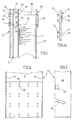
- a cylindrical coin tube is indicated at 10 in FIG. Located in the tube 10 a coin column 11.
- the tube 10 consists of a transparent plastic material.
- the coin tube adjoins a wall section 12 on the left side, the part of a housing not shown in FIG. 1 for a money changer forms.
- the housing is generally U-shaped in cross-section and takes on the top Area a coin validator on and in the lower area the changer, the Storage of the coins is done in a series of coin tubes, which follows below is still received.
- Wall section 12 is a circuit board 14 is arranged on which (not shown) the electronic components for operating a money changer are arranged.
- a light element 16 approximately in shape, on the circuit board 14 an LED and light-sensitive receiving element 18 are arranged.
- the Components are attached using SMD technology, the "line of sight" of the optical components directed through openings 20, 22 to the coin tube 10 out.
- the wall section 12 is also provided with openings 24, 26 which lead to the openings 20, 22 are aligned.
- the coin tube 10 has "windows" at 28 and 30. They are in one piece with the Coin tube 10 planform and z. B. (not shown) a little lower Wall thickness than the tube 10 in the remaining area. It is also possible in the field of Windows 28, 30 to make the material clearer than in the rest of the coin tube 10.
- the windows 28, 30 are of a raised frame 32 or 34 at least partially surrounded, the frame, which is not shown in Fig. 1, on the Wall section 12 can rest. They serve to prevent larger amounts to scattered light that emerges from the opening 24 in the direction of the tube 10 for Side is steered.
- the frame 34 prevents the light element 16 light coming directly into the opening 26 and to the light element 18 arrives.
- a prism 36 is formed in one piece with the coin tube 10.
- the prism serves to deflect the light beam 38 coming from the light element 16 downwards and back to the receiving element 18.
- the reflected beam is labeled 40.
- the arrangement of a prism for a light barrier is as already described above became known per se.
- the prism is on the outside of a raised one Surround frame 42, which also has the task of preventing stray light from entering to limit the prism.
- the windows 28, 30 are on the inside of the tube 10 provided with recesses 29, 31, which prevent scratching by coins.
- the above-mentioned housing is indicated at 44. It is in Cross-section U-shaped, being perpendicular to the sides of the wall section 12 protruding sidewall portions 46, 48 are formed. It can be seen from Fig. 2 that four columns with four pairs of holes 24, 26 are provided. Each column corresponds a coin tube, which is arranged in front of the perforated columns (not shown). The Upper pairs of holes 24, 26 are used to determine the upper fill level of the coin tube. The lower ones are used to determine the lower fill level. The middle serve to determine medium levels. One pair of holes each is a light barrier arrangement assigned as described in Fig. 1.
- the side wall sections 46, 48 have receiving slots, one of which is at 50 is shown.
- the slots 50 are to the free edge of the wall sections 46, 48 open.
- Above the receiving slots 50 is a rectangular opening 52 in the Wall sections 46, 48 formed. The slots and opening will be shown below still received.
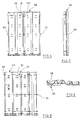
- FIG. 4 shows a series of four coin tubes 54 to 60 in perspective.
- the cassette-shaped arrangement of the coin tubes 54 to 60 is of an U-shaped section Surround cover 62.
- the lower ends of the coin tubes are 54 to 60 provided with payment arrangements, but did not go into further detail shall be. They are state of the art.
- FIG. 4 The side that can be seen in FIG. 4 is the rear side of the arrangement, which faces the inside of the housing 44 has.
- the coin tubes 54 to 60 are formed from two shells, which together form the cylindrical Coin tubes result.
- Fig. 4 the shell facing towards the inside is closed detect.
- This shell is shown in Fig. 6 from the inside and in Fig. 8 from the outside.
- she is designated 66.
- the configuration of the shell 66 results from the overall view the fig. 6 to 8.
- Fig. 9 you can see the partial cylinder 68, the partial cylinders the second bowl form the coin tubes 54 to 60.
- the shell 66 has on opposite edges at 68 or 70 cones protruding outwards are aligned with the pegs of the second shell and lie against one another in order to lock corresponding recesses in the cover 62. 4 are recesses represented at 72.
- 76 denotes the second shell, which the others Partial cylinder 78 forms. A row of four can be seen for each partial cylinder 78 Prisms 36, which are surrounded by a raised frame 42.
- the bowl 76 has pins 80, 82 on the side edges, those with pins 68, 70 of the shell 66 cooperate.
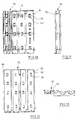
- FIG. 14 shows the inside, FIG. 15 the side view and FIG. 16 the Top view of the cover 62.
- the cover 62 is U-shaped in section with a web wall section 90 and leg wall sections 92, 94.
- angular Formed sections 96, 98 which are articulated in the region of the side wall sections 92, 94 are (see FIG. 15) and have a nose 100 in the region of the wall section 90.
- the angular sections 96, 98 have a hole 102 through which a finger can reach through to pull the nose 100 inwards.
- a pin 104 is formed on the outside of each of the wall sections 92, 94. In the Wall sections 92, 94 are also formed locking openings 106.
- the shells 66, 76 are held against one another, the lateral ones Projections 68, 70, 80, 82 lie against each other. Then the Arrangement inserted into the U-shaped extension 62, as shown in Fig. 4. The projections 68, 70, 80, 82 lying together snap into the openings 72 the cover 62 to hold the parts against each other. You can also use Can be attached to each other using a screw attachment.
- the Shell 66 three screw base 110 approximately in the longitudinal center, with corresponding Screw bases 112 of the shell 76 are aligned. With the help of a Screw which is guided through the base 110, 112 and into a base 114 of the Cover 62 is screwed in, the unit according to FIGS. 4 and 5 is sufficient Strength is maintained to the relatively high weight of the coins in the coin tubes 54 to catch up to 60.
- the pins 104 engage the side wall sections 92, 94 the cover 62 in the receiving slot 50 of the side walls 46, 48 of the housing.
- the lugs 100 of the angular sections 96, 98 snap into the latching opening 52. In this way, the cassette is sufficiently secured in the housing, but can can be removed in a few simple steps.
- the release of the lugs 100 from the Locking openings 52 are made simply by actuating the angle sections 98, 96, by engaging the respective opening 102 with a finger in order to To pivot angular sections 98, 96.
Landscapes
- Physics & Mathematics (AREA)
- General Physics & Mathematics (AREA)
- Control Of Vending Devices And Auxiliary Devices For Vending Devices (AREA)
- Inspection Of Paper Currency And Valuable Securities (AREA)
Applications Claiming Priority (2)
| Application Number | Priority Date | Filing Date | Title |
|---|---|---|---|
| DE20305319U DE20305319U1 (de) | 2003-04-02 | 2003-04-02 | Geldwechsler |
| DE20305319U | 2003-04-02 |
Publications (2)
| Publication Number | Publication Date |
|---|---|
| EP1465122A2 true EP1465122A2 (fr) | 2004-10-06 |
| EP1465122A3 EP1465122A3 (fr) | 2005-05-25 |
Family
ID=27763108
Family Applications (1)
| Application Number | Title | Priority Date | Filing Date |
|---|---|---|---|
| EP04006039A Withdrawn EP1465122A3 (fr) | 2003-04-02 | 2004-03-13 | Changeur de monnaie |
Country Status (3)
| Country | Link |
|---|---|
| US (1) | US7147551B2 (fr) |
| EP (1) | EP1465122A3 (fr) |
| DE (1) | DE20305319U1 (fr) |
Families Citing this family (6)
| Publication number | Priority date | Publication date | Assignee | Title |
|---|---|---|---|---|
| DE102004034149A1 (de) * | 2004-07-15 | 2006-02-09 | National Rejectors, Inc. Gmbh | Verfahren zum Betrieb eines Münzprüfer-Geldwechslers |
| WO2008008783A1 (fr) * | 2006-07-10 | 2008-01-17 | Coin Acceptors, Inc. | MONNAYEUR avec une cassette de stockage de pièces de monnaie ÉCLAIRÉE ayant des signaux de retour audibles et visuels |
| WO2008009022A2 (fr) * | 2006-07-14 | 2008-01-17 | Coin Acceptors, Inc. | Cassette de stockage de pièces de monnaie |
| TW201320009A (zh) * | 2011-11-04 | 2013-05-16 | Int Currency Tech | 硬幣找換系統 |
| CN103136837A (zh) * | 2011-11-28 | 2013-06-05 | 吉鸿电子股份有限公司 | 硬币找换系统 |
| JP6437256B2 (ja) * | 2014-09-18 | 2018-12-12 | 株式会社日本コンラックス | 硬貨収納カセット |
Family Cites Families (15)
| Publication number | Priority date | Publication date | Assignee | Title |
|---|---|---|---|---|
| US4221227A (en) | 1978-08-09 | 1980-09-09 | Mars, Incorporated | Separable coin storage tube assembly |
| GB2044972B (en) | 1979-03-26 | 1983-06-15 | Mars Inc | Coin detector |
| GB2065949B (en) | 1979-10-08 | 1984-05-16 | Nippon Coinco Co Ltd | Coin dispensing apparatus |
| GB2144252B (en) * | 1983-07-28 | 1987-04-23 | Mars Inc | Coin testing apparatus |
| US4541547A (en) * | 1983-10-21 | 1985-09-17 | Miknyocki Ronald J | Token or card dispenser |
| DE8800692U1 (de) | 1988-01-21 | 1988-05-05 | Nsm-Apparatebau Gmbh & Co Kg, 6530 Bingen | Vorrichtung zur Ermittlung des Füllstandes eines Münzstapelrohres |
| GB2250622B (en) | 1990-12-07 | 1994-09-14 | Mars Inc | Coin validators |
| GB2262982B (en) | 1991-10-16 | 1995-05-10 | Mars Inc | Coin mechanism having coin level sensor |
| DE9306231U1 (de) * | 1993-04-24 | 1993-07-01 | National Rejectors, Inc. GmbH, 2150 Buxtehude | Sortiervorrichtung für Münzen |
| FI963444A7 (fi) * | 1994-03-04 | 1996-11-01 | Austel Licensing Gmbh | Kolikoiden tunnistusmenetelmä ja -laite |
| US5830055A (en) * | 1996-11-07 | 1998-11-03 | Telequip Corporation | Coin/token canister and ejection mechanism |
| DE19848949C2 (de) | 1997-10-28 | 2003-06-18 | Leuze Electronic Gmbh & Co | Verfahren zum Betrieb einer Lichtschranke |
| US6044952A (en) | 1998-05-18 | 2000-04-04 | Mars, Incorporated | Multi-function optical sensor for a document acceptor |
| US6827647B1 (en) * | 2000-09-06 | 2004-12-07 | Wms Gaming, Inc. | Gaming machine coin handling system with dedicated local microcontroller |
| DE10215467A1 (de) * | 2002-03-28 | 2003-10-09 | Walter Hanke Mech Werkstaetten | Münzweiche |
-
2003
- 2003-04-02 DE DE20305319U patent/DE20305319U1/de not_active Expired - Lifetime
-
2004
- 2004-03-13 EP EP04006039A patent/EP1465122A3/fr not_active Withdrawn
- 2004-04-01 US US10/816,379 patent/US7147551B2/en not_active Expired - Lifetime
Also Published As
| Publication number | Publication date |
|---|---|
| EP1465122A3 (fr) | 2005-05-25 |
| DE20305319U1 (de) | 2003-08-14 |
| US20040198210A1 (en) | 2004-10-07 |
| US7147551B2 (en) | 2006-12-12 |
Similar Documents
| Publication | Publication Date | Title |
|---|---|---|
| DE3876256T2 (de) | Verkaufsautomat mit einer muenzrueckgabeeinrichtung. | |
| EP0622763B1 (fr) | Appareil pour trier des pièces de monnaie | |
| DE3806723C2 (de) | Zwischenkasse für Selbstverkäufer | |
| DE69604517T2 (de) | Wertmarkeneinführschacht | |
| DE20305319U1 (de) | Geldwechsler | |
| DE10213293A1 (de) | Münzbrett | |
| DE3810095C2 (fr) | ||
| EP0680021B1 (fr) | Dispositif pour détecter le niveau dans les tubes d'un distributeur de pièces de monnaie | |
| DE19515017C2 (de) | Zustellungszugriffvorrichtung | |
| EP2040226B1 (fr) | Dispositif destiné à trier des pièces de monnaie | |
| EP2023300A1 (fr) | Appareil à monnaie doté de plusieurs rouleaux de monnaie | |
| DE69116335T2 (de) | Zeitweiliger speicher von münzen für automaten | |
| DE19726460B4 (de) | Modular aufgebaute Münzeinheit | |
| DE3335825C2 (de) | Vorrichtung zur Sicherung eines Münzprüfers | |
| DE3874089T2 (de) | Muenzbetaetigte vorrichtung. | |
| DE2929379C2 (de) | Münzprüfer mit einer in einer Trägerplatte gelagerten, drehbaren Münzwaage | |
| DE4439009C2 (de) | Geldbetätigtes Unterhaltungsgerät | |
| DE2813183A1 (de) | Mehrfachmuenzpruefer | |
| DE102004034149A1 (de) | Verfahren zum Betrieb eines Münzprüfer-Geldwechslers | |
| DE19611352A1 (de) | Münzbetätigtes Unterhaltungsgerät | |
| DE20017237U1 (de) | Spielgerät, insbesondere Geldspielgerät | |
| DE1574241C3 (de) | Münzwerk zum Selbstkassieren von aus zwei Münzsorten unterschiedlichen Durchmessers zusammengesetzten Beträgen | |
| DE3522229A1 (de) | Elektronischer muenzpruefer | |
| DE4244816C2 (de) | Münzdurchlaufadapter | |
| DE10310474B4 (de) | Münzprüfer für Automaten mit einer Vorrichtung zur Verhinderung einer Manipulation |
Legal Events
| Date | Code | Title | Description |
|---|---|---|---|
| PUAI | Public reference made under article 153(3) epc to a published international application that has entered the european phase |
Free format text: ORIGINAL CODE: 0009012 |
|
| AK | Designated contracting states |
Kind code of ref document: A2 Designated state(s): AT BE BG CH CY CZ DE DK EE ES FI FR GB GR HU IE IT LI LU MC NL PL PT RO SE SI SK TR |
|
| AX | Request for extension of the european patent |
Extension state: AL LT LV MK |
|
| PUAL | Search report despatched |
Free format text: ORIGINAL CODE: 0009013 |
|
| AK | Designated contracting states |
Kind code of ref document: A3 Designated state(s): AT BE BG CH CY CZ DE DK EE ES FI FR GB GR HU IE IT LI LU MC NL PL PT RO SE SI SK TR |
|
| AX | Request for extension of the european patent |
Extension state: AL LT LV MK |
|
| 17P | Request for examination filed |
Effective date: 20050906 |
|
| AKX | Designation fees paid |
Designated state(s): AT BE BG CH CY CZ DE DK EE ES FI FR GB GR HU IE IT LI LU MC NL PL PT RO SE SI SK TR |
|
| STAA | Information on the status of an ep patent application or granted ep patent |
Free format text: STATUS: THE APPLICATION IS DEEMED TO BE WITHDRAWN |
|
| 18D | Application deemed to be withdrawn |
Effective date: 20121002 |