EP1465217A1 - Procédé et appareil pour démagnétiser des objets - Google Patents
Procédé et appareil pour démagnétiser des objets Download PDFInfo
- Publication number
- EP1465217A1 EP1465217A1 EP03405222A EP03405222A EP1465217A1 EP 1465217 A1 EP1465217 A1 EP 1465217A1 EP 03405222 A EP03405222 A EP 03405222A EP 03405222 A EP03405222 A EP 03405222A EP 1465217 A1 EP1465217 A1 EP 1465217A1
- Authority
- EP
- European Patent Office
- Prior art keywords
- coils
- alternating field
- series resonant
- resonant circuit
- objects
- Prior art date
- Legal status (The legal status is an assumption and is not a legal conclusion. Google has not performed a legal analysis and makes no representation as to the accuracy of the status listed.)
- Withdrawn
Links
- 238000000034 method Methods 0.000 title claims abstract description 31
- 230000008569 process Effects 0.000 title claims description 12
- 230000005347 demagnetization Effects 0.000 claims description 24
- 238000012937 correction Methods 0.000 claims description 3
- 230000005291 magnetic effect Effects 0.000 description 15
- 230000005389 magnetism Effects 0.000 description 6
- 230000005294 ferromagnetic effect Effects 0.000 description 5
- 239000000463 material Substances 0.000 description 5
- 230000035515 penetration Effects 0.000 description 4
- 238000010924 continuous production Methods 0.000 description 3
- 230000000694 effects Effects 0.000 description 3
- 238000002203 pretreatment Methods 0.000 description 3
- 238000013016 damping Methods 0.000 description 2
- 238000004519 manufacturing process Methods 0.000 description 2
- 230000009467 reduction Effects 0.000 description 2
- 206010014357 Electric shock Diseases 0.000 description 1
- XEEYBQQBJWHFJM-UHFFFAOYSA-N Iron Chemical group [Fe] XEEYBQQBJWHFJM-UHFFFAOYSA-N 0.000 description 1
- 230000008901 benefit Effects 0.000 description 1
- 239000003990 capacitor Substances 0.000 description 1
- 230000008859 change Effects 0.000 description 1
- 230000007423 decrease Effects 0.000 description 1
- 230000003247 decreasing effect Effects 0.000 description 1
- 230000005611 electricity Effects 0.000 description 1
- 238000005516 engineering process Methods 0.000 description 1
- 230000007613 environmental effect Effects 0.000 description 1
- 238000002474 experimental method Methods 0.000 description 1
- 238000012423 maintenance Methods 0.000 description 1
- 238000005259 measurement Methods 0.000 description 1
- 230000010355 oscillation Effects 0.000 description 1
- 230000008439 repair process Effects 0.000 description 1
Images
Classifications
-
- H—ELECTRICITY
- H01—ELECTRIC ELEMENTS
- H01F—MAGNETS; INDUCTANCES; TRANSFORMERS; SELECTION OF MATERIALS FOR THEIR MAGNETIC PROPERTIES
- H01F13/00—Apparatus or processes for magnetising or demagnetising
- H01F13/006—Methods and devices for demagnetising of magnetic bodies, e.g. workpieces, sheet material
Definitions
- the invention relates to a method and a device for demagnetizing Objects according to the preambles of the independent claims.
- a known method for demagnetizing objects uses an open one Magnetic circuit with a coil through which a constant alternating current flows.
- the magnetic core is placed on the object and the alternating current is switched on.
- the magnetic core is then slowly pulled away from the object by hand.
- a Device for this method are limited in size and weight of the magnetic core Demagnetization is strongly influenced by environmental conditions and is not precise reproducible. Demagnetization is incomplete and not always equally good.
- a coil tunnel is used worked with large electromagnets through which alternating current flows.
- the Object is pulled through the coil tunnel with a stationary magnetic field.
- the demagnetizing effect is limited.
- the effect improved by mechanically rotating the electromagnets.
- the object of the invention is to provide a method with which objects so far can be demagnetized so that there is no longer any measurable residual magnetism.
- Another object of the invention is to provide a device with which correspond to the process objects can be demagnetized.
- the method is suitable for all types of ferromagnetic Parts such as stamped parts, turned parts, springs, pipes, etc.
- the entire system in this Case the ferromagnetic objects as a whole are completely demagnetized.
- the ferromagnetic objects by an alternating magnetic field is pulled through, they remain locally in the magnetic field for a certain time within a station.
- the change of the alternating field in this station controlled by the coils electronically in terms of frequency and amplitude electronically to be controlled.
- the alternating field is brought to zero at the station, whereupon the ferromagnetic objects come out the station. They are now demagnetized to the extent that none Residual magnetism is more measurable.
- the demagnetization process takes place in cycles instead of.
- the frames and attachments of shadow masks on screens represent a special case for which the procedure follows pre-treatment.
- At the Processes with pretreatment are first magnetically hard spots, such as weld seams, Air gaps and so on in the workpiece to be treated locally locally with high fields by means of a rod choke coil, a coil with a rod-shaped laminated iron core, in Alternating field pre-treated. This makes these magnetically hard spots at least partially demagnetized.
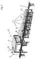
- the device according to FIG. 1 shows an embodiment which is based on these basic ideas is working.
- the demagnetization device comprises a transport route 1 on which the objects to be demagnetized are transported to, away and further.
- the Transport route leads through the demagnetization station 3.
- Transportstrasse 1 leads under one or several pretreatment stations 2 and then to Demagnetization station 3.
- Each pretreatment station 2 comprises a rod choke coil 21-24 in and of itself known type.
- the demagnetization station 3 comprises two opposite one another Boxes 31, 32, each comprising a coil.
- the two boxes with each other spaced coils form a zone in which a homogeneous field is generated.
- the Both coils are part of a series resonant circuit, which is created using an inverter is current controlled. They have no core.
- the two coils in boxes 31, 32 are are arranged opposite each other on both sides of a conveyor belt.
- the objects are now in time on the transport line from the pre-treatment station 2 to pretreatment station 2 and finally through demagnetization station 3 transported.
- the item remains in each station for a certain period of time.
- the magnetically hard spots are caused by strong fields pretreated so that they can no longer be identified as such and the magnetic properties are reasonably balanced.
- the cycle times are the problem or the treatment times in the individual Stations adjusted
- the longest treatment time in one of the stations is the Clock rate. Automation is possible
- the penetration depth of the magnetic strength is the same with the same amplitude of the alternating field the object depends on the frequency of the alternating field. This is also the Given the time of stay.
- a material is suitable for 1mm thick Frequency of the alternating field of about 200 Hz, which means a pulse time of at least 0.5 Seconds. With increasing penetration depth or material thickness the frequency decreases. For an object with a material thickness of 10mm, this corresponds to required frequency of the alternating field about 10 Hz.
- the residence time of the object in the alternating field must be at least one Correspond to a time span of the order of 100 periods or alternating pulses.
- the object In During this time of stay, the object must remain within the alternating field. So it will an influencing time of at least 10 seconds is required. Preferably during this influence time the transport stopped, so that the object is stationary in the Alternating field remains.
- the demagnetization frequency is a Compromise between the production speed, with the highest possible frequency, and the depth of penetration, which requires a lower frequency. From these specifications, the Resonance frequency of the entire resonant circuit is set. Everyone Demagnetization begins at this resonance frequency. At this starting point the object affects the resonance frequency negligibly, since the system in the Range of magnetic saturation is operated.
- the station includes two Boxes, one on each side of the item.
- they are two coils of the series resonant circuit to form a single long air coil summarized. The area with the alternating field is then located lengthways inside inside the long air coil.
- the series resonant circuit is now controlled by a power source. This happens with one Current regulator or an inverter. The effect of the magnetic field is independent of the Temperature in the coil kept constant. This leaves the field created without unwanted temperature influence precisely.
- the current regulator comes with a Provide zero point correction. The zero point correction symmetrizes the by the Series resonant circuit flowing current, so that no DC voltage element arises. So is at the time the item is removed from the station, none Tension and no more charge present.
- the two each other opposite coils are preferably polarized equally in terms of magnetic field.
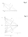
- the internal Programming, or the ramp function of the inverter used for control. You start the inverter and thus the series resonant circuit at the resonance frequency. Then let the inverter series resonant circuit system shut down. The one through the internal Programming frequency and voltage reduction in the inverter is done in one Ratio of about 1:20. This results in the current reduction in the series resonant circuit in the Range from 1.1000 to 1: 5000.
- the demagnetization curve thus corresponds approximately to that Exponential curve E of Figure 2
- the alternating field is, according to those described above Principles, during a period of expiration of between 20 and 500 periods or alternating pulses from the resonance frequency at time T0 to zero at time T ( Figure 3) dismantled. scaled back. Experiments were conducted with a length of stay between 50 and 250 periods always achieved very good results in demagnetization.
- the alternating field is also used during a period of time the expiry of between 20 and 500 periods or alternating pulses from the Resonance frequency at time T0 reduced to zero at time T ( Figure 3) resp scaled back.
- the optimal length of stay is approximately 100 Periods.
- the vibration in the series resonant circuit is controlled by a current controller controlled by current.
- FIG. 2 shows examples of demagnetization curves as are now possible using this clocked method.
- the series resonant circuit brings a usual exponential curve E by decaying vibrations. You can now determine the time period in which the residual magnetism in the object can be brought down to values that are no longer measurable. During this period, the object remains in the area between the two adjacent coils of the series resonant circuit.
- a separate current control is used.
- the start of the The process starts at the resonance frequency at maximum current Swing out series oscillating circuit damping during the required decay time At.
- the Control of the series resonant circuit is an inverter external current control of the Inverters with rectangular pulses are used.
- the demagnetization curve influenced by using individual or each of the vibrations at the beginning of the climb through additional supply of the series resonant circuit by means of rectangular pulses. Therefore the separate current control of the inverter is suitable. This allows the damping of the Vibrations and thus the demagnetization process according to the problem to get voted.
- the duration of the process is given by the principles mentioned above.
- the object After the controlled oscillation of the series resonant circuit, the object is removed taken from the station. It is no longer a voltage, a charge, or a magnetic field available. This is an extraordinary advantage for the demagnetizing device.
- the transport of the objects through the conveyor belt takes place in a clocked manner at the start-stop or fast - slow operation. This is during the stop - or slow phase Workpiece within the alternating field.
- After swinging out of the series resonant circuit there is no more voltage. There is no more electricity and there are no more charges available. There is also no risk of electric shock for Operators So when the device is finally turned off, too no residual loads left. This makes repairs and maintenance, e.g. at the Conveyor belt, completely harmless.
Landscapes
- Engineering & Computer Science (AREA)
- Power Engineering (AREA)
- General Induction Heating (AREA)
Priority Applications (2)
| Application Number | Priority Date | Filing Date | Title |
|---|---|---|---|
| EP03405222A EP1465217A1 (fr) | 2003-04-02 | 2003-04-02 | Procédé et appareil pour démagnétiser des objets |
| US10/603,646 US7196894B2 (en) | 2003-04-02 | 2003-06-25 | Method and a device for demagnetising objects |
Applications Claiming Priority (2)
| Application Number | Priority Date | Filing Date | Title |
|---|---|---|---|
| EP03405222A EP1465217A1 (fr) | 2003-04-02 | 2003-04-02 | Procédé et appareil pour démagnétiser des objets |
| US10/603,646 US7196894B2 (en) | 2003-04-02 | 2003-06-25 | Method and a device for demagnetising objects |
Publications (1)
| Publication Number | Publication Date |
|---|---|
| EP1465217A1 true EP1465217A1 (fr) | 2004-10-06 |
Family
ID=34196168
Family Applications (1)
| Application Number | Title | Priority Date | Filing Date |
|---|---|---|---|
| EP03405222A Withdrawn EP1465217A1 (fr) | 2003-04-02 | 2003-04-02 | Procédé et appareil pour démagnétiser des objets |
Country Status (2)
| Country | Link |
|---|---|
| US (1) | US7196894B2 (fr) |
| EP (1) | EP1465217A1 (fr) |
Cited By (5)
| Publication number | Priority date | Publication date | Assignee | Title |
|---|---|---|---|---|
| EP1765050A3 (fr) * | 2005-09-14 | 2009-11-11 | Siemens Electronics Assembly Systems GmbH & Co. KG | Dispositif d'alimentation en composants électriques |
| EP2263242A4 (fr) * | 2008-03-28 | 2012-01-04 | Shawcor Ltd | Système et procédé de désaimantation |
| CN103187140A (zh) * | 2011-12-28 | 2013-07-03 | 杭州飞宇磁电器材有限公司 | 隧道扫描通过式退磁机 |
| CN104319059A (zh) * | 2014-07-21 | 2015-01-28 | 浙江科技学院 | 一种五金工具自动充磁流水线 |
| EP2851911A1 (fr) | 2013-09-06 | 2015-03-25 | Albert Maurer | Élimination du magnétisme anhystérétique dans des corps ferromagnétiques |
Families Citing this family (13)
| Publication number | Priority date | Publication date | Assignee | Title |
|---|---|---|---|---|
| US8026722B2 (en) * | 2004-12-20 | 2011-09-27 | Smith International, Inc. | Method of magnetizing casing string tubulars for enhanced passive ranging |
| ATE476745T1 (de) * | 2005-11-24 | 2010-08-15 | Albert Maurer | Entmagnetisierungsverfahren durch wechselstromimpulse in einer in schlaufen gelegten leiterschleife |
| EP1796113A1 (fr) * | 2005-12-10 | 2007-06-13 | Maurer, Albert | Réglage automatique de la fréquence de résonance de démagnétisation des piéces différentes pour installations de démagnetisation |
| US20090072937A1 (en) * | 2006-06-05 | 2009-03-19 | John Holley | Steel pipe demagnetizing tool |
| KR101229020B1 (ko) * | 2006-06-22 | 2013-02-01 | 엘지디스플레이 주식회사 | 쉐도우 마스크의 자성제거 방법 및 그 장치 |
| US7538650B2 (en) * | 2006-07-17 | 2009-05-26 | Smith International, Inc. | Apparatus and method for magnetizing casing string tubulars |
| CH698521B1 (de) * | 2007-02-21 | 2009-08-31 | Albert Maurer | Entmagnetisierverfahren. |
| US9238959B2 (en) | 2010-12-07 | 2016-01-19 | Schlumberger Technology Corporation | Methods for improved active ranging and target well magnetization |
| US10094850B2 (en) | 2014-06-27 | 2018-10-09 | Schlumberger Technology Corporation | Magnetic ranging while rotating |
| US10031153B2 (en) | 2014-06-27 | 2018-07-24 | Schlumberger Technology Corporation | Magnetic ranging to an AC source while rotating |
| CN104240896A (zh) * | 2014-10-14 | 2014-12-24 | 鞍钢附企冷轧金属制品厂 | 用于消除钢板磁性的消磁机 |
| RU2636929C2 (ru) * | 2016-02-16 | 2017-11-29 | Российская Федерация, От Имени Которой Выступает Министерство Промышленности И Торговли Российской Федерации | Способ размагничивания крупногабаритного ферромагнитного изделия |
| USD949106S1 (en) * | 2019-11-18 | 2022-04-19 | Maurer Magnetic Ag | Demagnetization apparatus |
Citations (2)
| Publication number | Priority date | Publication date | Assignee | Title |
|---|---|---|---|---|
| US3506884A (en) * | 1967-03-29 | 1970-04-14 | Milton A Mckinley | Magnetic tape degaussing unit |
| GB2052873A (en) * | 1979-06-25 | 1981-01-28 | Riv Officine Di Villar Perosa | Demagnetizing devices |
Family Cites Families (8)
| Publication number | Priority date | Publication date | Assignee | Title |
|---|---|---|---|---|
| US1988040A (en) * | 1931-06-22 | 1935-01-15 | Herbert Edward Geisler | Process for the treatment of metals |
| NL6803012A (fr) * | 1968-03-02 | 1969-09-04 | ||
| DE2411485A1 (de) * | 1974-03-11 | 1975-09-18 | Nix Steingroeve Elektro Physik | Pruefgeraet fuer dauermagnete |
| DE3005927A1 (de) * | 1980-02-16 | 1981-09-03 | Erich Dr.-Ing. 5300 Bonn Steingroever | Entmagnetisier-verfahren |
| US4470094A (en) * | 1980-07-14 | 1984-09-04 | Electro-Matic Products Co. | Demagnetizing apparatus and method |
| US4360854A (en) * | 1980-12-12 | 1982-11-23 | Electro-Matic Products Co. | Demagnetizing, variable frequency |
| US4672345A (en) | 1985-09-24 | 1987-06-09 | Electro-Matic Products Co. | Degausser/demagnetizer |
| US5341263A (en) * | 1992-10-13 | 1994-08-23 | Recoton Corporation | Apparatus for demagnetizing the magnetic head of a cassette tape recording and/or reproducing device |
-
2003
- 2003-04-02 EP EP03405222A patent/EP1465217A1/fr not_active Withdrawn
- 2003-06-25 US US10/603,646 patent/US7196894B2/en not_active Expired - Lifetime
Patent Citations (2)
| Publication number | Priority date | Publication date | Assignee | Title |
|---|---|---|---|---|
| US3506884A (en) * | 1967-03-29 | 1970-04-14 | Milton A Mckinley | Magnetic tape degaussing unit |
| GB2052873A (en) * | 1979-06-25 | 1981-01-28 | Riv Officine Di Villar Perosa | Demagnetizing devices |
Cited By (6)
| Publication number | Priority date | Publication date | Assignee | Title |
|---|---|---|---|---|
| EP1765050A3 (fr) * | 2005-09-14 | 2009-11-11 | Siemens Electronics Assembly Systems GmbH & Co. KG | Dispositif d'alimentation en composants électriques |
| EP2263242A4 (fr) * | 2008-03-28 | 2012-01-04 | Shawcor Ltd | Système et procédé de désaimantation |
| CN103187140A (zh) * | 2011-12-28 | 2013-07-03 | 杭州飞宇磁电器材有限公司 | 隧道扫描通过式退磁机 |
| CN103187140B (zh) * | 2011-12-28 | 2015-07-29 | 杭州飞宇磁电器材有限公司 | 隧道扫描通过式退磁机 |
| EP2851911A1 (fr) | 2013-09-06 | 2015-03-25 | Albert Maurer | Élimination du magnétisme anhystérétique dans des corps ferromagnétiques |
| CN104319059A (zh) * | 2014-07-21 | 2015-01-28 | 浙江科技学院 | 一种五金工具自动充磁流水线 |
Also Published As
| Publication number | Publication date |
|---|---|
| US7196894B2 (en) | 2007-03-27 |
| US20040263300A1 (en) | 2004-12-30 |
Similar Documents
| Publication | Publication Date | Title |
|---|---|---|
| EP1465217A1 (fr) | Procédé et appareil pour démagnétiser des objets | |
| DE69728998T2 (de) | Apparat zur anderung des magnetischen zustands eines dauernmagneten | |
| DE3005927C2 (fr) | ||
| DE69827336T2 (de) | Heizspulen-Vorrichtung mit Reihen-Stromversorgung für Streifenförmige Produkte | |
| DE2815959A1 (de) | Beruehrungsloser stellungsfuehler | |
| EP0097773A1 (fr) | Aimant de levage avec dispositif de détection | |
| DE102008007896B4 (de) | Entmagnetisierverfahren | |
| DE3128263C2 (fr) | ||
| EP1791138A1 (fr) | Procédé de démagnétisation utilisant des impulsions de courant dans une boucle conductrice | |
| EP1353342B1 (fr) | Procédé et dispositif pour démagnétiser des objets | |
| DE19527827A1 (de) | Verfahren und Einrichtung zur Erzeugung elektrischer Wärme | |
| DE2652188C2 (de) | Vorrichtung zum Entnehmen von Werkstücken aus einem Behälter | |
| DE3500011C2 (de) | Verfahren zur geregelten Entmagnetisierung stabförmiger, ferromagnetischer und vergüteter Halb- oder Fertigfabrikate im laufenden Produktionsprozeß | |
| EP1796113A1 (fr) | Réglage automatique de la fréquence de résonance de démagnétisation des piéces différentes pour installations de démagnetisation | |
| DE734041C (de) | Verfahren und Einrichtung zum Entmagnetisieren von Stahlkoerpern | |
| DE487344C (de) | Elektromagneitsche Schuetteleinrichtung | |
| DE2223439C3 (de) | Verfahren und Gerat zum Entmagnetisieren ferromagnetischer Werkstoffe | |
| EP2963660B1 (fr) | Dispositif de demagnetisation non controle a courant alternatif | |
| EP0101922B1 (fr) | Procédé et dispositif pour traiter des matériaux ferro-magnétiques | |
| DE69702267T2 (de) | Elektromagnetisches aufhängungsgerät und verfahren zu dessen steuerung | |
| DE862931C (de) | Verfahren und Vorrichtung zum elektro-induktiven Erhitzen metallischer Werkstuecke | |
| DE2628048C2 (de) | Verfahren zum tiegelfreien Zonenschmelzen eines Halbleiterkristallstabes | |
| DE1913611B2 (de) | Annaeherungsschalter | |
| DE1623915B2 (de) | Materialzufuehrungseinrichtung | |
| DE2025813C3 (de) | Verfahren und Vorrichtung zur Induktionserhitzung von Flachkörpern |
Legal Events
| Date | Code | Title | Description |
|---|---|---|---|
| PUAI | Public reference made under article 153(3) epc to a published international application that has entered the european phase |
Free format text: ORIGINAL CODE: 0009012 |
|
| AK | Designated contracting states |
Kind code of ref document: A1 Designated state(s): AT BE BG CH CY CZ DE DK EE ES FI FR GB GR HU IE IT LI LU MC NL PT RO SE SI SK TR |
|
| AX | Request for extension of the european patent |
Extension state: AL LT LV MK |
|
| 17P | Request for examination filed |
Effective date: 20050404 |
|
| AKX | Designation fees paid |
Designated state(s): CH DE LI |
|
| STAA | Information on the status of an ep patent application or granted ep patent |
Free format text: STATUS: THE APPLICATION HAS BEEN WITHDRAWN |
|
| 18W | Application withdrawn |
Effective date: 20120426 |