EP1465314A2 - Module de protection contre la foudre à couplage du courant alternatif et bloquant le courant continu avec une function de dérivation du courant continu bloqué - Google Patents
Module de protection contre la foudre à couplage du courant alternatif et bloquant le courant continu avec une function de dérivation du courant continu bloqué Download PDFInfo
- Publication number
- EP1465314A2 EP1465314A2 EP04007606A EP04007606A EP1465314A2 EP 1465314 A2 EP1465314 A2 EP 1465314A2 EP 04007606 A EP04007606 A EP 04007606A EP 04007606 A EP04007606 A EP 04007606A EP 1465314 A2 EP1465314 A2 EP 1465314A2
- Authority
- EP
- European Patent Office
- Prior art keywords
- blocking
- functionality
- network equipment
- providing
- protection module
- Prior art date
- Legal status (The legal status is an assumption and is not a legal conclusion. Google has not performed a legal analysis and makes no representation as to the accuracy of the status listed.)
- Granted
Links
Images
Classifications
-
- H—ELECTRICITY
- H04—ELECTRIC COMMUNICATION TECHNIQUE
- H04M—TELEPHONIC COMMUNICATION
- H04M3/00—Automatic or semi-automatic exchanges
- H04M3/18—Automatic or semi-automatic exchanges with means for reducing interference or noise; with means for reducing effects due to line faults with means for protecting lines
-
- H—ELECTRICITY
- H04—ELECTRIC COMMUNICATION TECHNIQUE
- H04Q—SELECTING
- H04Q1/00—Details of selecting apparatus or arrangements
- H04Q1/02—Constructional details
- H04Q1/028—Subscriber network interface devices
-
- H—ELECTRICITY
- H04—ELECTRIC COMMUNICATION TECHNIQUE
- H04Q—SELECTING
- H04Q1/00—Details of selecting apparatus or arrangements
- H04Q1/02—Constructional details
- H04Q1/03—Power distribution arrangements
-
- H—ELECTRICITY
- H04—ELECTRIC COMMUNICATION TECHNIQUE
- H04M—TELEPHONIC COMMUNICATION
- H04M3/00—Automatic or semi-automatic exchanges
- H04M3/22—Arrangements for supervision, monitoring or testing
- H04M3/26—Arrangements for supervision, monitoring or testing with means for applying test signals or for measuring
- H04M3/28—Automatic routine testing ; Fault testing; Installation testing; Test methods, test equipment or test arrangements therefor
- H04M3/30—Automatic routine testing ; Fault testing; Installation testing; Test methods, test equipment or test arrangements therefor for subscriber's lines, for the local loop
Definitions
- the disclosures herein relate generally to surge protection devices and more particularly to surge protection devices configured for providing DC blocking functionality and/or AC coupling functionality.
- DLCs Digital Loop Carriers
- DSLAMs Digital Subscriber Access Multiplexers
- SSL Digital Subscriber Line
- POTS Peripheral Telephone Service
- ADSL Asymmetrical Digital Subscriber Line
- the protectors are also essentially transparent to metallic loop test systems that test for faults on the twisted wire pair between subscriber premise equipment and upstream network equipment.
- Embodiments of the disclosures made herein relate to a network equipment protection module for use with central office or remote DSL network equipment (e.g., DSLAMs, DLCs, etc).
- a network equipment protection module enables the combination of surge protection, DSL signal transmission, full metallic loop testing (MLT) and bridging of a DC power feed to be facilitated in association with a twisted pair transmission line (also referred to herein as a twisted wire pair) in a manner that overcomes limitations associated with conventional solutions for providing such functionality.
- voltage provided by power feed equipment e.g., nominally 200Vdc
- NTD subscriber premise DSL network termination device
- a DSL NTD is an example of such a subscriber premise DSL NTD that relies on voltage provided by power feed equipment via an attached twisted pair transmission line.
- a DSL NTD is an active device powered from upstream power feed equipment and which, in at least one embodiment, provides POTS functionality via ADSL data transmission (i.e., POTS talk battery voltage not provided over an attached twisted pair transmission line).
- Network equipment protection modules in accordance with embodiments of the disclosures made herein offer a number of benefits.
- One benefit is that they are direct replacements for conventional surge protectors as used in conventional protector blocks. Accordingly, they do not require any rewiring of the twisted pair transmission lines at the DLC or DSLAM cabinet.
- Another benefit is that they don't require costly replacement of combination ADSL/POTS cards at the DLC or DSLAM, thus being a less expensive approach.
- Still another benefit is that the overall approach requires no additional space in a DLC or DSLAM.
- Yet another benefit is that they do not inhibit full metallic loop testing.
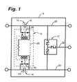
- the network equipment protection module 10 includes surge protection circuitry 12 configured for providing surge protection functionality, AC coupling-DC blocking circuitry 14 configured for providing AC coupling-DC blocking functionality and DC blocking bypass circuitry 16 configured for providing DC blocking bypass functionality.
- surge protection circuitry 12 configured for providing surge protection functionality
- AC coupling-DC blocking circuitry 14 configured for providing AC coupling-DC blocking functionality
- DC blocking bypass circuitry 16 configured for providing DC blocking bypass functionality.
- the surge protection circuitry 12, the AC coupling-DC blocking circuitry 14 and the DC blocking bypass circuitry 16 are all contained in a discrete packaging device 19.
- the discrete packaging device 19 is configured for being mounted on an unmodified commercially-available equipment protector block, which is OEM-configured for having conventional surge protectors mounted thereon.
- a commercially available equipment protector block is a 310-series equipment protector block offered by AVAYA Incorporated.
- AVAYA Incorporated is a commercially available equipment protector block offered by AVAYA Incorporated.
- AVAYA Incorporated is a commercially available equipment protector block.
- AVAYA Incorporated 310-series equipment protector block offered by AVAYA Incorporated.
- AVAYA Incorporated 310-series equipment protector block offered by AVAYA Incorporated.
- AVAYA Incorporated One example of such conventional surge protectors is a 5-pin surge protector module offered by Marconi Communications Incorporated.
- the AC coupling-DC blocking circuitry 14 includes a first capacitor 18 and a second capacitor 20 connected in series with a first power lead 22 and a second power lead 24, respectively (i.e., a pair of power leads).
- the first capacitor 18 and the second capacitor 20 represent one embodiment of means for providing AC coupling-DC blocking functionality.
- the first capacitor 18 and the second capacitor 20 have a capacitance of about 1 micro Farad. It will be appreciated that the specific capacitance for the capacitors (18, 20) will be specified dependent upon the specific implementation of the network equipment protection module 10.
- the DC blocking bypass circuitry 16 includes a control portion 26 connected between first power lead 22 and the second power lead 24.
- the control portion 26 is configured for enabling a first shunt 28 and a second shunt 30 to be selectively connected and disconnected across the first capacitor 18 and the second capacitor 20, respectively.
- a suitable DC voltage is applied across the pair of power leads (22, 24)
- the control portion 26 of the DC blocking bypass circuitry 16 is activated (i.e., in response to current flows through the control portion 26) and acts to disconnect the shunts (28, 30) from across the respective one of the capacitors (18, 20) whereby DC blocking functionality is activated.
- the control portion 26 of the DC blocking bypass circuitry 16 is deactivated, thereby deactivating (i.e., bypassing) DC blocking functionality by allowing the shunts (28, 30) to be connected across the respective one of the capacitors (18, 20).
- the DC blocking bypass circuitry 16 is configured for enabling the DC blocking bypass functionality to be selectively activated and deactivated.
- the DC blocking bypass circuitry 16 represents one embodiment of means for providing DC blocking bypass functionality.
- a pair of normally-closed relay paths is an example of the first shunt 28 and the second shunt 30. It is contemplated herein that such a pair of normally-closed relay paths may be facilitated via a single relay or a plurality of relays (e.g., 2 relays).
- An actuation coil relay of a single relay is one example of the control portion 26 of the DC blocking bypass circuitry 16.
- Actuation coils of a pair of relays having a resistor connected therebetween are another example of the control portion 26 of the DC blocking bypass circuitry 16.
- Embodiments of the disclosures made herein are not limited to solid-state and mechanical relays, but may utilize any useful circuitry or component that provides relay functionality.
- the surge protection circuitry 12 is connected between the pair of power leads (22, 24) and a ground lead 32.
- a Transient Voltage Suppression (TVS) device such as a SIDACtor brand TVS device or similar TVS device is an example of the surge protection circuitry 12.
- the surge protection circuitry 12 is an example of means for providing surge protection.
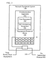
- FIG. 2 depicts an embodiment of a network equipment system 100 in accordance with an embodiment of the disclosures made herein.
- the network equipment system 100 includes a communication apparatus 102, an equipment protector block 104 and a plurality of network equipment protection modules 10 (as disclosed above in reference to FIG. 1) mounted on the equipment protector block 104.
- the equipment protector block 104 is connected between the communication apparatus 102 and a subscriber premise DSL NTD (not shown) via a twisted pair transmission line 105.
- the equipment protector block in a DLC and DSLAM is preinstalled and pre-wired to the communication apparatus 102 (or at least to a backplane through which connections to such apparatus is made).
- a DC voltage (e.g. -200Vdc), which is supplied by power feed equipment (not shown), is bridged onto the twisted pair transmission line 105 (e.g., at a junction block).
- power feed equipment may be located locally or remotely with respect to the communication apparatus 102.
- the DC blocking circuitry 16 of the network equipment protection modules 10 inhibits the DC power feed voltage from being applied to the communication apparatus 102.
- the communication apparatus 102 includes DSL multiplexing equipment 106 and test equipment 108.
- the equipment protection block 104 is connected to the DSL multiplexing equipment 106 and/or the test equipment 108. It is contemplated that the equipment protection block 104 is connected directly to the DSL multiplexing equipment 106 and that the test equipment 108 transmits signals downstream through the equipment protection block 104 via the DSL multiplexing equipment 106.
- a DLC e.g., a common control shelf and channel bank assemblies
- a DSLAM are two examples of the DSL multiplexing equipment 106.
- the test equipment 108 is configured for performing Metallic Loop Test (MLT) functionality. Accordingly, MLT test equipment is an example of the test equipment 108.
- the combination of the equipment protector block 104 and at least one of the network equipment protection modules 10 is an example of a network equipment protection apparatus.
- a plurality of network equipment protection modules 10 is plugged into (or otherwise operably mounted on) the equipment protection block 102.
- One or more of the network equipment protection modules 10 may replace one or more conventional surge protectors mounted thereon.
- Each one of the network equipment protection modules 10 is configured for providing surge protection, AC coupling-DC blocking functionality and DC blocking bypass functionality.
- the DC blocking bypass functionality allows full metallic loop testing to be performed while the power feed (i.e., DC voltage) is removed from the twisted pair transmission line 105.
Landscapes
- Engineering & Computer Science (AREA)
- Computer Networks & Wireless Communication (AREA)
- Signal Processing (AREA)
- Power Engineering (AREA)
- Emergency Protection Circuit Devices (AREA)
Applications Claiming Priority (2)
| Application Number | Priority Date | Filing Date | Title |
|---|---|---|---|
| US404231 | 2003-04-01 | ||
| US10/404,231 US7518847B2 (en) | 2003-04-01 | 2003-04-01 | AC coupling-DC blocking surge protection module with DC blocking bypass functionality |
Publications (3)
| Publication Number | Publication Date |
|---|---|
| EP1465314A2 true EP1465314A2 (fr) | 2004-10-06 |
| EP1465314A3 EP1465314A3 (fr) | 2005-01-19 |
| EP1465314B1 EP1465314B1 (fr) | 2007-01-03 |
Family
ID=32850587
Family Applications (1)
| Application Number | Title | Priority Date | Filing Date |
|---|---|---|---|
| EP04007606A Expired - Lifetime EP1465314B1 (fr) | 2003-04-01 | 2004-03-30 | Module de protection contre la foudre à couplage du courant alternatif et bloquant le courant continu avec une function de dérivation du courant continu bloqué |
Country Status (4)
| Country | Link |
|---|---|
| US (2) | US7518847B2 (fr) |
| EP (1) | EP1465314B1 (fr) |
| AT (1) | ATE350799T1 (fr) |
| DE (1) | DE602004003985T2 (fr) |
Cited By (1)
| Publication number | Priority date | Publication date | Assignee | Title |
|---|---|---|---|---|
| WO2012047978A1 (fr) * | 2010-10-05 | 2012-04-12 | Illinois Tool Works Inc. | Ensemble protecteur de signal d'entrée/sortie à montage sur bâti pour protection vis-à-vis des pointes |
Families Citing this family (6)
| Publication number | Priority date | Publication date | Assignee | Title |
|---|---|---|---|---|
| US7656811B2 (en) * | 2005-12-12 | 2010-02-02 | At&T Intellectual Property I, L.P. | Digital subscriber line access multiplexer wiring validation |
| EP2472281A1 (fr) * | 2011-01-03 | 2012-07-04 | Alcatel Lucent | Procédé et système pour étalonner une première méthode d'estimation de la valeur d'une caractéristique de boucle utilisant une première caractéristique de boucle localement mesurable et un premier ensemble de paramètres |
| CN103491458B (zh) * | 2013-09-24 | 2017-02-01 | 北京国科环宇空间技术有限公司 | 支持OpenVPX标准的无配线通信模块 |
| DE102013112511A1 (de) * | 2013-11-14 | 2015-05-21 | Phoenix Contact Gmbh & Co. Kg | Kommunikationsmodul |
| TWI553985B (zh) * | 2015-04-16 | 2016-10-11 | 安雷科技有限公司 | 用於對稱雙絞線之保護模組及其解耦組件 |
| CN106486992A (zh) * | 2015-08-27 | 2017-03-08 | 中兴通讯股份有限公司 | 一种具有振荡特性的接口保护电路及方法 |
Family Cites Families (14)
| Publication number | Priority date | Publication date | Assignee | Title |
|---|---|---|---|---|
| JPS6086995A (ja) * | 1983-10-18 | 1985-05-16 | Nec Corp | 外来電流保護方式 |
| US5546267A (en) * | 1994-12-08 | 1996-08-13 | Illinois Tool Works Inc. | Communication circuit protector |
| US5795182A (en) * | 1996-07-25 | 1998-08-18 | Modern Technology Inventions | Polarity independent battery jumper cables or charger with automatic polarity detector and built-in automatic safety features |
| US6259775B1 (en) * | 1997-09-05 | 2001-07-10 | Martin A. Alpert | Multi-line modem interface |
| US6377435B1 (en) * | 1998-10-28 | 2002-04-23 | Emerson Electric Co. | Circuit design for data/telephone tip/ring pair surge protection |
| US6757377B1 (en) * | 1998-12-30 | 2004-06-29 | Paradyne Corporation | Central office filter system and method |
| AU764023B2 (en) * | 1999-01-20 | 2003-08-07 | Oakdene Limited | The testing of telephone lines |
| US6236664B1 (en) * | 1999-06-04 | 2001-05-22 | Terayon Communications Systems, Inc. | Pair gain system with an ADSL repeater unit |
| US7031446B2 (en) * | 1999-12-23 | 2006-04-18 | Analog Devices, Inc. | Device for use in communication systems |
| US6785325B1 (en) * | 2000-06-07 | 2004-08-31 | Nortel Networks Limited | DSL splitter providing test access to an interconnected subscriber loop and method |
| US6535581B2 (en) * | 2001-05-31 | 2003-03-18 | Mphase Technologies | Bypass for telephone system splitter |
| FR2825530B1 (fr) * | 2001-05-31 | 2003-08-15 | Seventech | Dispositif de protection contre les surtensions |
| US7231354B1 (en) * | 2002-11-12 | 2007-06-12 | Bellsouth Intellectual Property Corporation | Method, apparatus, and computer-readable medium for administering the implementation of product change notices |
| US7480367B2 (en) * | 2002-12-12 | 2009-01-20 | Adc Dsl Systems, Inc. | Fault characterization using information indicative of echo |
-
2003
- 2003-04-01 US US10/404,231 patent/US7518847B2/en not_active Expired - Lifetime
-
2004
- 2004-03-30 AT AT04007606T patent/ATE350799T1/de not_active IP Right Cessation
- 2004-03-30 EP EP04007606A patent/EP1465314B1/fr not_active Expired - Lifetime
- 2004-03-30 DE DE602004003985T patent/DE602004003985T2/de not_active Expired - Lifetime
-
2009
- 2009-02-18 US US12/378,697 patent/US20090154049A1/en not_active Abandoned
Cited By (1)
| Publication number | Priority date | Publication date | Assignee | Title |
|---|---|---|---|---|
| WO2012047978A1 (fr) * | 2010-10-05 | 2012-04-12 | Illinois Tool Works Inc. | Ensemble protecteur de signal d'entrée/sortie à montage sur bâti pour protection vis-à-vis des pointes |
Also Published As
| Publication number | Publication date |
|---|---|
| EP1465314A3 (fr) | 2005-01-19 |
| US20090154049A1 (en) | 2009-06-18 |
| US20040196602A1 (en) | 2004-10-07 |
| DE602004003985T2 (de) | 2007-11-08 |
| EP1465314B1 (fr) | 2007-01-03 |
| ATE350799T1 (de) | 2007-01-15 |
| US7518847B2 (en) | 2009-04-14 |
| DE602004003985D1 (de) | 2007-02-15 |
Similar Documents
| Publication | Publication Date | Title |
|---|---|---|
| US20090154049A1 (en) | Network equipment system providing surge protection and DC blocking bypass functionalities | |
| US6574309B1 (en) | Remotely actuated splittler bypass system and method | |
| US6998964B2 (en) | Splitter | |
| EP1843566A1 (fr) | Procédé et dispositifs pour fournir un courant mouillant | |
| US6738474B1 (en) | System for providing pots splitters externally with respect to digital subscriber loop access multiplexers and remote terminal and central office equipment racks | |
| US7787614B2 (en) | Sealing current terminator for inhibiting oxidation and methods therefor | |
| EP3143758B1 (fr) | Appareil et procédé de détection de téléphone décroché en architecture d'alimentation par l'équipement du client | |
| EP1760903B1 (fr) | Unite enfichable pour test large bande, carte enfichable pour test large bande et testeur large bande | |
| US6831930B1 (en) | Access panel for network end linesharing ADSL/POTS splitter applications | |
| US8780695B2 (en) | Device and system for protection switching | |
| US8488747B1 (en) | Modified protector module with an integrated splitter | |
| US7760858B2 (en) | Splitter system and test access | |
| EP1650900B1 (fr) | Appareil de test de ligne d'utilisateur et système de communication à bande large et à bande étroite | |
| EP1248444A1 (fr) | Appareil téléphonique de test analogue possedant un filtre passe-bas et des resistances couplées avec les lignes de connection pour prévenir l'alteration des signaux de communication numériques | |
| WO2007132162A1 (fr) | Améliorations de l'approvisionnement en services xdsl | |
| US20010040962A1 (en) | Telephone test set-installed low pass filter circuit for preventing corruption of digital communication signals | |
| US8855293B2 (en) | Frame injected DSL via face fed protector module | |
| US20040057188A1 (en) | System and method for providing telephone service restrictions | |
| EP3174272B1 (fr) | Dispositif de séparation et arrangement | |
| US8159958B1 (en) | Krone block dongle |
Legal Events
| Date | Code | Title | Description |
|---|---|---|---|
| PUAI | Public reference made under article 153(3) epc to a published international application that has entered the european phase |
Free format text: ORIGINAL CODE: 0009012 |
|
| AK | Designated contracting states |
Kind code of ref document: A2 Designated state(s): AT BE BG CH CY CZ DE DK EE ES FI FR GB GR HU IE IT LI LU MC NL PL PT RO SE SI SK TR |
|
| AX | Request for extension of the european patent |
Extension state: AL LT LV MK |
|
| PUAL | Search report despatched |
Free format text: ORIGINAL CODE: 0009013 |
|
| AK | Designated contracting states |
Kind code of ref document: A3 Designated state(s): AT BE BG CH CY CZ DE DK EE ES FI FR GB GR HU IE IT LI LU MC NL PL PT RO SE SI SK TR |
|
| AX | Request for extension of the european patent |
Extension state: AL LT LV MK |
|
| RIC1 | Information provided on ipc code assigned before grant |
Ipc: 7H 04M 3/18 B Ipc: 7H 02H 9/04 A |
|
| 17P | Request for examination filed |
Effective date: 20050622 |
|
| AKX | Designation fees paid |
Designated state(s): AT BE BG CH CY CZ DE DK EE ES FI FR GB GR HU IE IT LI LU MC NL PL PT RO SE SI SK TR |
|
| GRAP | Despatch of communication of intention to grant a patent |
Free format text: ORIGINAL CODE: EPIDOSNIGR1 |
|
| GRAS | Grant fee paid |
Free format text: ORIGINAL CODE: EPIDOSNIGR3 |
|
| GRAA | (expected) grant |
Free format text: ORIGINAL CODE: 0009210 |
|
| AK | Designated contracting states |
Kind code of ref document: B1 Designated state(s): AT BE BG CH CY CZ DE DK EE ES FI FR GB GR HU IE IT LI LU MC NL PL PT RO SE SI SK TR |
|
| PG25 | Lapsed in a contracting state [announced via postgrant information from national office to epo] |
Ref country code: NL Free format text: LAPSE BECAUSE OF FAILURE TO SUBMIT A TRANSLATION OF THE DESCRIPTION OR TO PAY THE FEE WITHIN THE PRESCRIBED TIME-LIMIT Effective date: 20070103 Ref country code: AT Free format text: LAPSE BECAUSE OF FAILURE TO SUBMIT A TRANSLATION OF THE DESCRIPTION OR TO PAY THE FEE WITHIN THE PRESCRIBED TIME-LIMIT Effective date: 20070103 Ref country code: PL Free format text: LAPSE BECAUSE OF FAILURE TO SUBMIT A TRANSLATION OF THE DESCRIPTION OR TO PAY THE FEE WITHIN THE PRESCRIBED TIME-LIMIT Effective date: 20070103 Ref country code: SI Free format text: LAPSE BECAUSE OF FAILURE TO SUBMIT A TRANSLATION OF THE DESCRIPTION OR TO PAY THE FEE WITHIN THE PRESCRIBED TIME-LIMIT Effective date: 20070103 Ref country code: LI Free format text: LAPSE BECAUSE OF FAILURE TO SUBMIT A TRANSLATION OF THE DESCRIPTION OR TO PAY THE FEE WITHIN THE PRESCRIBED TIME-LIMIT Effective date: 20070103 Ref country code: DK Free format text: LAPSE BECAUSE OF FAILURE TO SUBMIT A TRANSLATION OF THE DESCRIPTION OR TO PAY THE FEE WITHIN THE PRESCRIBED TIME-LIMIT Effective date: 20070103 Ref country code: FI Free format text: LAPSE BECAUSE OF FAILURE TO SUBMIT A TRANSLATION OF THE DESCRIPTION OR TO PAY THE FEE WITHIN THE PRESCRIBED TIME-LIMIT Effective date: 20070103 Ref country code: CH Free format text: LAPSE BECAUSE OF FAILURE TO SUBMIT A TRANSLATION OF THE DESCRIPTION OR TO PAY THE FEE WITHIN THE PRESCRIBED TIME-LIMIT Effective date: 20070103 |
|
| REG | Reference to a national code |
Ref country code: GB Ref legal event code: FG4D |
|
| REF | Corresponds to: |
Ref document number: 602004003985 Country of ref document: DE Date of ref document: 20070215 Kind code of ref document: P |
|
| REG | Reference to a national code |
Ref country code: IE Ref legal event code: FG4D |
|
| PG25 | Lapsed in a contracting state [announced via postgrant information from national office to epo] |
Ref country code: SE Free format text: LAPSE BECAUSE OF FAILURE TO SUBMIT A TRANSLATION OF THE DESCRIPTION OR TO PAY THE FEE WITHIN THE PRESCRIBED TIME-LIMIT Effective date: 20070403 |
|
| PG25 | Lapsed in a contracting state [announced via postgrant information from national office to epo] |
Ref country code: BG Free format text: LAPSE BECAUSE OF FAILURE TO SUBMIT A TRANSLATION OF THE DESCRIPTION OR TO PAY THE FEE WITHIN THE PRESCRIBED TIME-LIMIT Effective date: 20070404 |
|
| RAP2 | Party data changed (patent owner data changed or rights of a patent transferred) |
Owner name: ALCATEL LUCENT |
|
| PG25 | Lapsed in a contracting state [announced via postgrant information from national office to epo] |
Ref country code: ES Free format text: LAPSE BECAUSE OF FAILURE TO SUBMIT A TRANSLATION OF THE DESCRIPTION OR TO PAY THE FEE WITHIN THE PRESCRIBED TIME-LIMIT Effective date: 20070414 |
|
| NLT2 | Nl: modifications (of names), taken from the european patent patent bulletin |
Owner name: ALCATEL LUCENT Effective date: 20070404 |
|
| PG25 | Lapsed in a contracting state [announced via postgrant information from national office to epo] |
Ref country code: PT Free format text: LAPSE BECAUSE OF FAILURE TO SUBMIT A TRANSLATION OF THE DESCRIPTION OR TO PAY THE FEE WITHIN THE PRESCRIBED TIME-LIMIT Effective date: 20070604 |
|
| NLV1 | Nl: lapsed or annulled due to failure to fulfill the requirements of art. 29p and 29m of the patents act | ||
| REG | Reference to a national code |
Ref country code: CH Ref legal event code: PL |
|
| ET | Fr: translation filed | ||
| PLBE | No opposition filed within time limit |
Free format text: ORIGINAL CODE: 0009261 |
|
| STAA | Information on the status of an ep patent application or granted ep patent |
Free format text: STATUS: NO OPPOSITION FILED WITHIN TIME LIMIT |
|
| PG25 | Lapsed in a contracting state [announced via postgrant information from national office to epo] |
Ref country code: SK Free format text: LAPSE BECAUSE OF FAILURE TO SUBMIT A TRANSLATION OF THE DESCRIPTION OR TO PAY THE FEE WITHIN THE PRESCRIBED TIME-LIMIT Effective date: 20070103 |
|
| 26N | No opposition filed |
Effective date: 20071005 |
|
| PG25 | Lapsed in a contracting state [announced via postgrant information from national office to epo] |
Ref country code: BE Free format text: LAPSE BECAUSE OF FAILURE TO SUBMIT A TRANSLATION OF THE DESCRIPTION OR TO PAY THE FEE WITHIN THE PRESCRIBED TIME-LIMIT Effective date: 20070103 Ref country code: CZ Free format text: LAPSE BECAUSE OF FAILURE TO SUBMIT A TRANSLATION OF THE DESCRIPTION OR TO PAY THE FEE WITHIN THE PRESCRIBED TIME-LIMIT Effective date: 20070103 Ref country code: RO Free format text: LAPSE BECAUSE OF FAILURE TO SUBMIT A TRANSLATION OF THE DESCRIPTION OR TO PAY THE FEE WITHIN THE PRESCRIBED TIME-LIMIT Effective date: 20070103 |
|
| PG25 | Lapsed in a contracting state [announced via postgrant information from national office to epo] |
Ref country code: MC Free format text: LAPSE BECAUSE OF NON-PAYMENT OF DUE FEES Effective date: 20070331 Ref country code: IE Free format text: LAPSE BECAUSE OF NON-PAYMENT OF DUE FEES Effective date: 20070330 |
|
| PG25 | Lapsed in a contracting state [announced via postgrant information from national office to epo] |
Ref country code: GR Free format text: LAPSE BECAUSE OF FAILURE TO SUBMIT A TRANSLATION OF THE DESCRIPTION OR TO PAY THE FEE WITHIN THE PRESCRIBED TIME-LIMIT Effective date: 20070404 |
|
| PG25 | Lapsed in a contracting state [announced via postgrant information from national office to epo] |
Ref country code: EE Free format text: LAPSE BECAUSE OF FAILURE TO SUBMIT A TRANSLATION OF THE DESCRIPTION OR TO PAY THE FEE WITHIN THE PRESCRIBED TIME-LIMIT Effective date: 20070103 |
|
| PG25 | Lapsed in a contracting state [announced via postgrant information from national office to epo] |
Ref country code: CY Free format text: LAPSE BECAUSE OF FAILURE TO SUBMIT A TRANSLATION OF THE DESCRIPTION OR TO PAY THE FEE WITHIN THE PRESCRIBED TIME-LIMIT Effective date: 20070103 |
|
| PG25 | Lapsed in a contracting state [announced via postgrant information from national office to epo] |
Ref country code: LU Free format text: LAPSE BECAUSE OF NON-PAYMENT OF DUE FEES Effective date: 20070330 |
|
| PG25 | Lapsed in a contracting state [announced via postgrant information from national office to epo] |
Ref country code: HU Free format text: LAPSE BECAUSE OF FAILURE TO SUBMIT A TRANSLATION OF THE DESCRIPTION OR TO PAY THE FEE WITHIN THE PRESCRIBED TIME-LIMIT Effective date: 20070704 Ref country code: TR Free format text: LAPSE BECAUSE OF FAILURE TO SUBMIT A TRANSLATION OF THE DESCRIPTION OR TO PAY THE FEE WITHIN THE PRESCRIBED TIME-LIMIT Effective date: 20070103 |
|
| PGFP | Annual fee paid to national office [announced via postgrant information from national office to epo] |
Ref country code: IT Payment date: 20110324 Year of fee payment: 8 |
|
| PG25 | Lapsed in a contracting state [announced via postgrant information from national office to epo] |
Ref country code: IT Free format text: LAPSE BECAUSE OF NON-PAYMENT OF DUE FEES Effective date: 20120330 |
|
| REG | Reference to a national code |
Ref country code: FR Ref legal event code: GC Effective date: 20140717 |
|
| REG | Reference to a national code |
Ref country code: FR Ref legal event code: RG Effective date: 20141016 |
|
| REG | Reference to a national code |
Ref country code: FR Ref legal event code: PLFP Year of fee payment: 12 |
|
| REG | Reference to a national code |
Ref country code: FR Ref legal event code: CA Effective date: 20150521 |
|
| REG | Reference to a national code |
Ref country code: FR Ref legal event code: CA Effective date: 20150521 |
|
| REG | Reference to a national code |
Ref country code: FR Ref legal event code: PLFP Year of fee payment: 13 |
|
| REG | Reference to a national code |
Ref country code: FR Ref legal event code: PLFP Year of fee payment: 14 |
|
| PGFP | Annual fee paid to national office [announced via postgrant information from national office to epo] |
Ref country code: FR Payment date: 20170322 Year of fee payment: 14 Ref country code: DE Payment date: 20170322 Year of fee payment: 14 |
|
| PGFP | Annual fee paid to national office [announced via postgrant information from national office to epo] |
Ref country code: GB Payment date: 20170322 Year of fee payment: 14 |
|
| REG | Reference to a national code |
Ref country code: DE Ref legal event code: R119 Ref document number: 602004003985 Country of ref document: DE |
|
| GBPC | Gb: european patent ceased through non-payment of renewal fee |
Effective date: 20180330 |
|
| PG25 | Lapsed in a contracting state [announced via postgrant information from national office to epo] |
Ref country code: DE Free format text: LAPSE BECAUSE OF NON-PAYMENT OF DUE FEES Effective date: 20181002 |
|
| PG25 | Lapsed in a contracting state [announced via postgrant information from national office to epo] |
Ref country code: GB Free format text: LAPSE BECAUSE OF NON-PAYMENT OF DUE FEES Effective date: 20180330 |
|
| PG25 | Lapsed in a contracting state [announced via postgrant information from national office to epo] |
Ref country code: FR Free format text: LAPSE BECAUSE OF NON-PAYMENT OF DUE FEES Effective date: 20180331 |