EP1465320A2 - Verfahren und System zum automatischen Prüfen von elektrischen Geräten, insbesonders Haushaltsgeräten, und Vorrichtung zur Ausführung desselben Verfahrens - Google Patents
Verfahren und System zum automatischen Prüfen von elektrischen Geräten, insbesonders Haushaltsgeräten, und Vorrichtung zur Ausführung desselben Verfahrens Download PDFInfo
- Publication number
- EP1465320A2 EP1465320A2 EP04007881A EP04007881A EP1465320A2 EP 1465320 A2 EP1465320 A2 EP 1465320A2 EP 04007881 A EP04007881 A EP 04007881A EP 04007881 A EP04007881 A EP 04007881A EP 1465320 A2 EP1465320 A2 EP 1465320A2
- Authority
- EP
- European Patent Office
- Prior art keywords
- electric appliance
- monitoring device
- electric
- information
- test
- Prior art date
- Legal status (The legal status is an assumption and is not a legal conclusion. Google has not performed a legal analysis and makes no representation as to the accuracy of the status listed.)
- Withdrawn
Links
Images




Classifications
-
- H—ELECTRICITY
- H02—GENERATION; CONVERSION OR DISTRIBUTION OF ELECTRIC POWER
- H02J—ELECTRIC POWER NETWORKS; CIRCUIT ARRANGEMENTS OR SYSTEMS FOR SUPPLYING OR DISTRIBUTING ELECTRIC POWER; SYSTEMS FOR STORING ELECTRIC ENERGY
- H02J13/00—Circuit arrangements for providing remote monitoring or remote control of equipment in a power distribution network
- H02J13/12—Monitoring network conditions, e.g. electrical magnitudes or operational status
-
- H—ELECTRICITY
- H02—GENERATION; CONVERSION OR DISTRIBUTION OF ELECTRIC POWER
- H02J—ELECTRIC POWER NETWORKS; CIRCUIT ARRANGEMENTS OR SYSTEMS FOR SUPPLYING OR DISTRIBUTING ELECTRIC POWER; SYSTEMS FOR STORING ELECTRIC ENERGY
- H02J13/00—Circuit arrangements for providing remote monitoring or remote control of equipment in a power distribution network
- H02J13/13—Circuit arrangements for providing remote monitoring or remote control of equipment in a power distribution network characterised by the transmission of data to equipment in the power network
- H02J13/1311—Circuit arrangements for providing remote monitoring or remote control of equipment in a power distribution network characterised by the transmission of data to equipment in the power network using the power network as support for the transmission
- H02J13/1315—Circuit arrangements for providing remote monitoring or remote control of equipment in a power distribution network characterised by the transmission of data to equipment in the power network using the power network as support for the transmission using modification of a parameter of the network power signal
-
- H—ELECTRICITY
- H02—GENERATION; CONVERSION OR DISTRIBUTION OF ELECTRIC POWER
- H02J—ELECTRIC POWER NETWORKS; CIRCUIT ARRANGEMENTS OR SYSTEMS FOR SUPPLYING OR DISTRIBUTING ELECTRIC POWER; SYSTEMS FOR STORING ELECTRIC ENERGY
- H02J13/00—Circuit arrangements for providing remote monitoring or remote control of equipment in a power distribution network
- H02J13/14—Circuit arrangements for providing remote monitoring or remote control of equipment in a power distribution network the power network being locally controlled, e.g. home energy management systems [HEMS]
-
- G—PHYSICS
- G01—MEASURING; TESTING
- G01R—MEASURING ELECTRIC VARIABLES; MEASURING MAGNETIC VARIABLES
- G01R31/00—Arrangements for testing electric properties; Arrangements for locating electric faults; Arrangements for electrical testing characterised by what is being tested not provided for elsewhere
- G01R31/28—Testing of electronic circuits, e.g. by signal tracer
- G01R31/282—Testing of electronic circuits specially adapted for particular applications not provided for elsewhere
- G01R31/2825—Testing of electronic circuits specially adapted for particular applications not provided for elsewhere in household appliances or professional audio/video equipment
-
- G—PHYSICS
- G01—MEASURING; TESTING
- G01R—MEASURING ELECTRIC VARIABLES; MEASURING MAGNETIC VARIABLES
- G01R31/00—Arrangements for testing electric properties; Arrangements for locating electric faults; Arrangements for electrical testing characterised by what is being tested not provided for elsewhere
- G01R31/40—Testing power supplies
- G01R31/42—AC power supplies
-
- H—ELECTRICITY
- H02—GENERATION; CONVERSION OR DISTRIBUTION OF ELECTRIC POWER
- H02J—ELECTRIC POWER NETWORKS; CIRCUIT ARRANGEMENTS OR SYSTEMS FOR SUPPLYING OR DISTRIBUTING ELECTRIC POWER; SYSTEMS FOR STORING ELECTRIC ENERGY
- H02J2105/00—Networks for supplying or distributing electric power characterised by their spatial reach or by the load
- H02J2105/10—Local stationary networks having a local or delimited stationary reach
- H02J2105/12—Local stationary networks having a local or delimited stationary reach supplying households or buildings
-
- Y—GENERAL TAGGING OF NEW TECHNOLOGICAL DEVELOPMENTS; GENERAL TAGGING OF CROSS-SECTIONAL TECHNOLOGIES SPANNING OVER SEVERAL SECTIONS OF THE IPC; TECHNICAL SUBJECTS COVERED BY FORMER USPC CROSS-REFERENCE ART COLLECTIONS [XRACs] AND DIGESTS
- Y02—TECHNOLOGIES OR APPLICATIONS FOR MITIGATION OR ADAPTATION AGAINST CLIMATE CHANGE
- Y02B—CLIMATE CHANGE MITIGATION TECHNOLOGIES RELATED TO BUILDINGS, e.g. HOUSING, HOUSE APPLIANCES OR RELATED END-USER APPLICATIONS
- Y02B90/00—Enabling technologies or technologies with a potential or indirect contribution to GHG emissions mitigation
- Y02B90/20—Smart grids as enabling technology in buildings sector
-
- Y—GENERAL TAGGING OF NEW TECHNOLOGICAL DEVELOPMENTS; GENERAL TAGGING OF CROSS-SECTIONAL TECHNOLOGIES SPANNING OVER SEVERAL SECTIONS OF THE IPC; TECHNICAL SUBJECTS COVERED BY FORMER USPC CROSS-REFERENCE ART COLLECTIONS [XRACs] AND DIGESTS
- Y02—TECHNOLOGIES OR APPLICATIONS FOR MITIGATION OR ADAPTATION AGAINST CLIMATE CHANGE
- Y02E—REDUCTION OF GREENHOUSE GAS [GHG] EMISSIONS, RELATED TO ENERGY GENERATION, TRANSMISSION OR DISTRIBUTION
- Y02E60/00—Enabling technologies; Technologies with a potential or indirect contribution to GHG emissions mitigation
-
- Y—GENERAL TAGGING OF NEW TECHNOLOGICAL DEVELOPMENTS; GENERAL TAGGING OF CROSS-SECTIONAL TECHNOLOGIES SPANNING OVER SEVERAL SECTIONS OF THE IPC; TECHNICAL SUBJECTS COVERED BY FORMER USPC CROSS-REFERENCE ART COLLECTIONS [XRACs] AND DIGESTS
- Y04—INFORMATION OR COMMUNICATION TECHNOLOGIES HAVING AN IMPACT ON OTHER TECHNOLOGY AREAS
- Y04S—SYSTEMS INTEGRATING TECHNOLOGIES RELATED TO POWER NETWORK OPERATION, COMMUNICATION OR INFORMATION TECHNOLOGIES FOR IMPROVING THE ELECTRICAL POWER GENERATION, TRANSMISSION, DISTRIBUTION, MANAGEMENT OR USAGE, i.e. SMART GRIDS
- Y04S40/00—Systems for electrical power generation, transmission, distribution or end-user application management characterised by the use of communication or information technologies, or communication or information technology specific aspects supporting them
- Y04S40/12—Systems for electrical power generation, transmission, distribution or end-user application management characterised by the use of communication or information technologies, or communication or information technology specific aspects supporting them characterised by data transport means between the monitoring, controlling or managing units and monitored, controlled or operated electrical equipment
- Y04S40/121—Systems for electrical power generation, transmission, distribution or end-user application management characterised by the use of communication or information technologies, or communication or information technology specific aspects supporting them characterised by data transport means between the monitoring, controlling or managing units and monitored, controlled or operated electrical equipment using the power network as support for the transmission
Definitions
- the assembly process of electric appliances is typically concluded with a test phase to check both the operation and/or performance of the electric appliance, such as the observance of the electric safety regulations and complete operation of each product before its packaging.
- a likely defective product is sent to an appropriate repair station and then submitted anew to a test procedure.
- the target of the test systems usually adopted in modern manufacturing plants of electric appliances, in particular household appliances, is to reach utmost test efficiency in the shortest time possible, so as to warrant a high quality of the result at a minimum cost.
- test systems often fail to actually warrant a complete check of all possible failures of a product just assembled; moreover, some times they request too long test times and consequent high costs, as it happens for the testing of refrigerating appliances, such as refrigerators, freezers, environment air-conditioning system, etc.
- probes and detecting instruments are needed in order to perform the test, which have to be introduced inside the appliance or co-operate with it to obtain the data required for executing the operation test and evaluate whether the performances of the appliance complies with the rated or theoretical ones.
- test system In order to warrant utmost completeness of the test, it would be appropriate to have the products to be tested, managed by a digital control system placed on board of the electric appliance, being able to communicate with the test system itself. In this instance, the test system is actually able to verify the operation of each electric component, such as sensors, resistors for the heating, compressors, motors, electrovalves, fans, pumps, lamps, etc., through the "cooperation" of the product itself under test
- test systems which ensure a direct dialog with the products under test.
- These known test systems are used, for instance, by the major manufacturers of digital controlled household appliances; however, for the time being these systems exclusively applied to high and/or very high class products, since they require appropriate communicating means on board of the products themselves (serial communication lines, infrared optical systems, ultrasound systems, radio-frequency systems, power line communication systems), the cost of which cannot be borne by medium or low class products, which represent anyway the great majority of the present production of household appliances.
- test systems for refrigerating appliances are also known, which can shorten test times with the help of temperature detecting systems making use of non invasive techniques, such as infrared telecameras which allow for the monitoring of temperature distribution in the outer portions of the product with time.
- non invasive techniques such as infrared telecameras which allow for the monitoring of temperature distribution in the outer portions of the product with time.
- these highly expensive systems require sophisticated algorithms for the analysis of the images and do not guarantee a complete check of all the possible failures of the tested product.
- the object of the present invention consists of a low-cost test system for executing a fast exhaustive check of the performance and possible failures of an electric appliance, in particular a household appliance, as well as of a relevant non invasive test method based on a direct dialog (i.e. requiring no specific wiring) between the test apparatus and the digital control system of the electric appliance under test which, in a preferred embodiment, does not require application of any sensors or measuring instruments on board of the electric appliance itself.
- Such a dialog is based on a peer-to-peer communication technique as described in the patent application PCT/IB01/00548 (International Publication Number: WO 02/21664 Al), according to which any electric appliance can exchange information with the outer environment by means of its power supply cable, without using expensive conventional communicating means (serial lines, infrared systems, radio-frequency systems, power line carrier communication systems, etc.), provided it is equipped with a digital control system, which can be very simple and thus low cost.
- PCT/IB01/00548 International Publication Number: WO 02/21664 Al
- an electric appliance (10, fig. 1) can exchange information with an external monitoring device (20, fig. 1) located between the electric appliance itself and its relevant power socket, according to the following two procedures:
- the above communication technique has the great advantage of requiring neither additional costs for the electric appliance (10), which would not be acceptable for this line of products, nor the need to choose a determined network protocol during production; however, all of it without giving up the opportunity of exchanging information with an external communication network, including the test system of the electric appliances delivered from the production line, being such a communication network reached indirectly through the monitoring device (20).
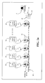
- the architecture of the test system according to the present invention shows a set of electric appliances (10), each one of them connected through their own supply cable (15) to the mains (40) by means of an appropriate monitoring system (20) appropriately connected to the communication network (18) to which a main control device (17), represented for instance by a Personal Computer, is also connected.
- the communication network (18) represented in Figure 1 is of the wired type, such as an RS-485 network or analogous, whereas the network represented in Figure 1a is a wireless one, such as a radio-frequency network.
- the monitoring device (20) shown in Figure 1 is a fixed device housed inside an appropriate power socket, whereas the one illustrated in Figure 1a is a movable one represented by an adaptor interlaying between the power socket and the supply cable of the electric appliance (10).
- the main controller (17) performs a master function for the monitoring devices (20), sending them appropriate instructions and providing for receiving and processing the information picked up by the last ones.
- the above information are partially generated by each monitoring device (20) and partially supplied by each electric appliance (10) through its supply cable, using the low cost communication technique described in the patent application PCT/IB01/00548 previously mentioned.
- the monitoring device (20) described in Figure 2 consists of the following function blocks:
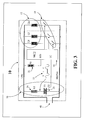
- the control system housed inside the electric appliance (10) is schematically represented in the Figure 3 highlighting the function blocks forming it:
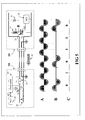
- the coding procedure of the information sent from the monitoring device (20) to the electric appliance (10) is graphically described in Figure 4, where the three waveforms A, B and C represent the mains voltage (40) supplying the monitoring device (20), the mains voltage (41) supplying the electric appliance (10) and containing the mains holes impressed by the monitoring device (20) through the triac (27) and, finally, the time intervals elapsing between the consecutive zero passages of the positive wave of the mains voltage (41) supplying the electric appliance (10), respectively.
- the different length of these time intervals depends on the quantity of the corresponding blackout of the mains voltage and contains the coded information transmitted from the monitoring device (20) to the electric appliance (10).
- the measure of the above time intervals is performed by the microcontroller (32) contained on board of the electric appliance (10) through an appropriate inner timer: based on the measure performed by this timer, the microcontroller (32) will decode the binary information contained in every time interval.
- the coding procedure of the information sent by the electric appliance (10) to the monitoring device (20) is graphically described in Figure 5, where the three waveforms A, B and C represent the mains voltage (40) supplying both the monitoring device (20) and the electric appliance (10), the voltage to the terminals of the triac (33) driving the resistive load (34) and the binary coding associated to the power absorptions of such a resistive load, respectively: a "logic one” can be associated e.g. to the power absorption of the load (34) in the frame of a whole mains cycle, whereas a "logic zero" is consequently associated to the lack of said absorption.
- test system for electric appliances (10), in particular household appliances, having the architecture of the type described above the method for performing the test according to the present invention is managed by the main control system (17) according to the following steps:
- the most prominent feature of the present invention is represented by the fact that the electric appliance (10) is tested just connecting it to the power socket of the test system, utilizing the electronics already on board normally used for other purposes; in other words, the test process can be totally automated through mechanical insertion of the plug of the power supply cable of the electric appliance in the power socket of the test system.
- FIG. 6 is illustrating an example of a highly advantageous application, where the electric appliance (10) is represented by a household refrigerator.
- the same application can be adopted for any other refrigerating apparatus, such as a freezer or an environment air conditioner.
- the most important benefit which can be obtained according to the present invention is represented in particular by a drastic shortening of the test time; the present test times, in the order of 1,5 - 2 hours, can be actually reduced to 10 - 15 minutes, with no use of sophisticated test instrumentations, such as infrared telecamera systems or insertion of special probes inside the appliance.
- the same lamp (35) typically present inside the refrigerating compartment can also be used as a resistive load (34), required for data transmission from the electric appliance (10) to the monitoring device (20); thus avoiding any cost increase for the control system electronics of the household appliance.
- the one represented in Figure 6 has an additional environment temperature sensor (16) connected to the main control system (17), being used for verifying the performance of the temperature sensors (one or more) located inside the refrigerator which, on the first activation of the product, should all detect a temperature close to the environment temperature of the manufacturing factory, since they are delivered directly from the assembly line and have not been supplied yet.
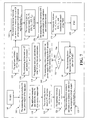
- test sequence for household refrigerators is described in the flow diagram of Figure 7, where for simplicity's sake it is assumed that each refrigerator is provided with only one temperature sensor.
- the test starts from the starting block (100) activating the voltage supply of the product under test, through the block (105).
- the control goes on to block (110), in which the refrigerator measures the temperature value detected by its inner sensor and sends it to the monitoring device (20) using the lamp (35) as a resistive load for data transmission through power absorptions.
- the control goes on to block (115), in which the monitoring device (20) receives and stores the data sent by the refrigerator (10) and transfers the control to the subsequent block (120), in which the refrigerator activates its own compressor on request of the monitoring device (20).
- this block (130) checks whether the time elapsed from the activation of the compressor is less than a preset value t F or not: in the affirmative case, one should wait; in the negative case (reaching time t F ), the control is transferred on the contrary to the block (140), in which the monitoring device (20) stops supplying the refrigerator for a number N of seconds and then restores it again, transferring the control to the block (145).
- the refrigerator (10) sends the temperature value presently detected by its inner sensor to the monitoring device (20) and transfers the control to the subsequent block (150).
- the monitoring device (20) receives and stores in its nonvolatile memory (21) the temperature value sent by the refrigerator (10), then transfers the control to the block (155); in line with this block the refrigerator activates the compressor again and transfers the control to the block (160).
- the monitoring device (20) measures and stores the value of the compressor's inrush current and duration of the starting transitory in its memory (21), then transfers the control to the block (165).
- the monitoring device (20) sends to the main control system (17) both the values of the temperature, the compressor's inrush current and duration of the starting transitory previously stored in its memory (21), then the control is transferred to the block (170).
- the monitoring device (20) stops supplying the refrigerator actually concluding the test, and transfers the control to the block (175), in which the main control system (17) is going to process the information data received from the monitoring device (20) and determine the test result; the control will be definitively transferred to the block (180), which terminates the test process of the refrigerator (10).
- the main control system (17) can issue a judgment on the operating level and/or performance of every appliance under test.
Landscapes
- Engineering & Computer Science (AREA)
- Power Engineering (AREA)
- Testing Electric Properties And Detecting Electric Faults (AREA)
- Testing Or Calibration Of Command Recording Devices (AREA)
Applications Claiming Priority (2)
| Application Number | Priority Date | Filing Date | Title |
|---|---|---|---|
| ITTO20030252 | 2003-04-01 | ||
| IT000252A ITTO20030252A1 (it) | 2003-04-01 | 2003-04-01 | Metodo e sistema per il collaudo automatico di |
Publications (2)
| Publication Number | Publication Date |
|---|---|
| EP1465320A2 true EP1465320A2 (de) | 2004-10-06 |
| EP1465320A3 EP1465320A3 (de) | 2007-09-05 |
Family
ID=32843931
Family Applications (1)
| Application Number | Title | Priority Date | Filing Date |
|---|---|---|---|
| EP04007881A Withdrawn EP1465320A3 (de) | 2003-04-01 | 2004-04-01 | Verfahren und System zum automatischen Prüfen von elektrischen Geräten, insbesonders Haushaltsgeräten, und Vorrichtung zur Ausführung desselben Verfahrens |
Country Status (2)
| Country | Link |
|---|---|
| EP (1) | EP1465320A3 (de) |
| IT (1) | ITTO20030252A1 (de) |
Cited By (12)
| Publication number | Priority date | Publication date | Assignee | Title |
|---|---|---|---|---|
| WO2006095217A1 (en) | 2005-03-09 | 2006-09-14 | Indesit Company S.P.A. | Household appliance comprising a lighting device and method for controlling the activation thereof |
| US7324911B2 (en) | 2004-06-29 | 2008-01-29 | Jds Uniphase Corporation | Method of planning, installing, and verifying a set of electrical cables in a building |
| US7366630B2 (en) | 2004-06-29 | 2008-04-29 | Jds Uniphase Corporation | Management of electrical cable installations in a building |
| WO2008090432A1 (en) * | 2007-01-24 | 2008-07-31 | Indesit Company S.P.A. | An electrical appliance, in particular an electrical household appliance, a corresponding optional auxiliary device, and a system comprising said appliance and device |
| CN101806869A (zh) * | 2010-03-22 | 2010-08-18 | 株洲南车时代电气股份有限公司 | 一种机车开关电源通用自动测试系统及其方法 |
| CN102230955A (zh) * | 2011-06-24 | 2011-11-02 | 株洲南车时代电气股份有限公司 | 一种机车开关电源动态老化监控系统及其方法 |
| CN102494909A (zh) * | 2011-11-17 | 2012-06-13 | 合肥美的荣事达电冰箱有限公司 | 一种冰箱的测试方法 |
| FR2980947A1 (fr) * | 2011-10-04 | 2013-04-05 | Ascodero Productique | Dispositif destine au controle et au nettoyage de casques audio filaires |
| ITTO20120738A1 (it) * | 2012-08-21 | 2014-02-22 | Indesit Co Spa | "sistema elettrodomestico" |
| EP2095142B1 (de) * | 2006-11-30 | 2016-07-13 | ANSALDI Pierluigi | Einrichtung zum detektieren und signalisieren von fehlfunktionen bei der verwendung elektrischer geräte |
| CN106885963A (zh) * | 2017-04-13 | 2017-06-23 | 合肥美菱股份有限公司 | 一种冰箱综合性能测试设备 |
| US9791877B2 (en) | 2012-08-21 | 2017-10-17 | Indesit Company S.P.A. | Electrical household appliance system |
Family Cites Families (4)
| Publication number | Priority date | Publication date | Assignee | Title |
|---|---|---|---|---|
| DD201227A1 (de) * | 1981-11-19 | 1983-07-06 | Axel Lorenz | Diagnoseschaltungssystem |
| US4628443A (en) * | 1984-11-16 | 1986-12-09 | General Electric Company | Test initiating apparatus for appliances having self-diagnostic testing capability |
| IT1257203B (it) * | 1992-05-29 | 1996-01-10 | Merloni Elettrodomestici Spa | Sistema automatico di collaudo funzionale per apparecchi elettrodomestici |
| IT1320621B1 (it) * | 2000-09-05 | 2003-12-10 | Wrap Spa | Metodo, sistema ed apparati per la trasmissione di dati su reteelettrica |
-
2003
- 2003-04-01 IT IT000252A patent/ITTO20030252A1/it unknown
-
2004
- 2004-04-01 EP EP04007881A patent/EP1465320A3/de not_active Withdrawn
Cited By (20)
| Publication number | Priority date | Publication date | Assignee | Title |
|---|---|---|---|---|
| US7324911B2 (en) | 2004-06-29 | 2008-01-29 | Jds Uniphase Corporation | Method of planning, installing, and verifying a set of electrical cables in a building |
| US7366630B2 (en) | 2004-06-29 | 2008-04-29 | Jds Uniphase Corporation | Management of electrical cable installations in a building |
| EP2282613A1 (de) | 2005-03-09 | 2011-02-09 | Indesit Company S.p.A. | Haushaltsgerät mit einer Beleuchtungsanordnung und Verfahren zur Betätigung der Anordnung |
| WO2006095217A1 (en) | 2005-03-09 | 2006-09-14 | Indesit Company S.P.A. | Household appliance comprising a lighting device and method for controlling the activation thereof |
| EP2095142B1 (de) * | 2006-11-30 | 2016-07-13 | ANSALDI Pierluigi | Einrichtung zum detektieren und signalisieren von fehlfunktionen bei der verwendung elektrischer geräte |
| WO2008090432A1 (en) * | 2007-01-24 | 2008-07-31 | Indesit Company S.P.A. | An electrical appliance, in particular an electrical household appliance, a corresponding optional auxiliary device, and a system comprising said appliance and device |
| EP2447796A1 (de) * | 2007-01-24 | 2012-05-02 | Indesit Company S.p.A. | Elektrische Anwendung, insbesondere ein elektrisches Haushaltsgerät, entsprechende optionale Hilfsvorrichtung und System mit besagter Anwendung und Vorrichtung |
| US8319599B2 (en) | 2007-01-24 | 2012-11-27 | Indesit Company S.P.A. | Electrical appliance, in particular an electrical household appliance, a corresponding optional auxiliary device, and a system comprising said appliance and device |
| CN101806869A (zh) * | 2010-03-22 | 2010-08-18 | 株洲南车时代电气股份有限公司 | 一种机车开关电源通用自动测试系统及其方法 |
| CN102230955B (zh) * | 2011-06-24 | 2013-06-19 | 株洲南车时代电气股份有限公司 | 一种机车开关电源动态老化监控系统及其方法 |
| CN102230955A (zh) * | 2011-06-24 | 2011-11-02 | 株洲南车时代电气股份有限公司 | 一种机车开关电源动态老化监控系统及其方法 |
| FR2980947A1 (fr) * | 2011-10-04 | 2013-04-05 | Ascodero Productique | Dispositif destine au controle et au nettoyage de casques audio filaires |
| WO2013050709A3 (fr) * | 2011-10-04 | 2014-02-20 | Association Des Paralyses De France Apf | Dispositif destiné au contrôle et au nettoyage de casques audio filaires |
| US9332340B2 (en) | 2011-10-04 | 2016-05-03 | Association Des Paralyses De France Apf | Device for controlling and cleaning wired audio headsets |
| CN102494909B (zh) * | 2011-11-17 | 2015-02-25 | 合肥美的电冰箱有限公司 | 一种冰箱的测试方法 |
| CN102494909A (zh) * | 2011-11-17 | 2012-06-13 | 合肥美的荣事达电冰箱有限公司 | 一种冰箱的测试方法 |
| ITTO20120738A1 (it) * | 2012-08-21 | 2014-02-22 | Indesit Co Spa | "sistema elettrodomestico" |
| WO2014030121A1 (en) * | 2012-08-21 | 2014-02-27 | Indesit Company S.P.A. | Electrical household appliance system |
| US9791877B2 (en) | 2012-08-21 | 2017-10-17 | Indesit Company S.P.A. | Electrical household appliance system |
| CN106885963A (zh) * | 2017-04-13 | 2017-06-23 | 合肥美菱股份有限公司 | 一种冰箱综合性能测试设备 |
Also Published As
| Publication number | Publication date |
|---|---|
| ITTO20030252A1 (it) | 2004-10-02 |
| EP1465320A3 (de) | 2007-09-05 |
Similar Documents
| Publication | Publication Date | Title |
|---|---|---|
| US7451244B2 (en) | Multi-protocol bus device | |
| US7296426B2 (en) | Interactive control system for an HVAC system | |
| US8386202B2 (en) | Communication device for household electric appliances and monitoring system using said device | |
| EP0716361B1 (de) | Serielle Bussteuerung für Geräte | |
| EP2652444B1 (de) | Verfahren und system zur identifizierung von mindestens einer durch eine stromversorgungsvorrichtung über eine stromleitungsverbindung elektrisch angetriebene vorrichtung | |
| RU2493662C2 (ru) | Шинное управление для бытового электроприбора | |
| CA1279117C (en) | Local control system for domestic appliances and alarm devices | |
| CN111288743A (zh) | 一种家用电器故障检测系统 | |
| US20210215367A1 (en) | Method of Auto Association of HVAC Energy with Control Signal for Self Diagnostics of the HVAC System | |
| US20060125607A1 (en) | System and method for identifying automation components | |
| CN103261986A (zh) | 用于测试和诊断液体分配器中的故障的系统和方法 | |
| CN105841312A (zh) | 一种房间空气调节器及远程检测控制系统 | |
| US6477849B2 (en) | Method and apparatus for testing heat pumps | |
| RU191782U1 (ru) | Датчик тока | |
| EP1446856B1 (de) | Verfahren und vorrichtung zur überwachung der elektrischen geräte | |
| CN111043721A (zh) | 一种can总线匹配电阻接入方法、装置、空调机组及系统 | |
| CN1153330A (zh) | 电器的串行总线控制 | |
| WO2018025740A1 (ja) | 通信装置、及び通信システム | |
| EP1949601B1 (de) | Hausautomatisierungssystem | |
| CN110686358B (zh) | 一种基于检测工装的变频空调器故障诊断方法 | |
| US6882949B2 (en) | Method and apparatus for testing heat pumps | |
| CN215340863U (zh) | 移动电源租赁设备的温度预警控制系统 | |
| CN214895731U (zh) | 检测装置 | |
| US6647346B1 (en) | Compressor control system and method therefor | |
| US9176494B2 (en) | System and method of communication for electronic apparatuses |
Legal Events
| Date | Code | Title | Description |
|---|---|---|---|
| PUAI | Public reference made under article 153(3) epc to a published international application that has entered the european phase |
Free format text: ORIGINAL CODE: 0009012 |
|
| AK | Designated contracting states |
Kind code of ref document: A2 Designated state(s): AT BE BG CH CY CZ DE DK EE ES FI FR GB GR HU IE IT LI LU MC NL PL PT RO SE SI SK TR |
|
| AX | Request for extension of the european patent |
Extension state: AL HR LT LV MK |
|
| RAP1 | Party data changed (applicant data changed or rights of an application transferred) |
Owner name: INDESIT COMPANY S.P.A. |
|
| PUAL | Search report despatched |
Free format text: ORIGINAL CODE: 0009013 |
|
| AK | Designated contracting states |
Kind code of ref document: A3 Designated state(s): AT BE BG CH CY CZ DE DK EE ES FI FR GB GR HU IE IT LI LU MC NL PL PT RO SE SI SK TR |
|
| AX | Request for extension of the european patent |
Extension state: AL HR LT LV MK |
|
| 17P | Request for examination filed |
Effective date: 20071212 |
|
| AKX | Designation fees paid |
Designated state(s): AT BE BG CH CY CZ DE DK EE ES FI FR GB GR HU IE IT LI LU MC NL PL PT RO SE SI SK TR |
|
| STAA | Information on the status of an ep patent application or granted ep patent |
Free format text: STATUS: THE APPLICATION IS DEEMED TO BE WITHDRAWN |
|
| 18D | Application deemed to be withdrawn |
Effective date: 20121101 |