EP1465349A1 - Quantificateurs scalaires imbriqués pour description multiple dans le cadre de la transmission progressive d'images - Google Patents
Quantificateurs scalaires imbriqués pour description multiple dans le cadre de la transmission progressive d'images Download PDFInfo
- Publication number
- EP1465349A1 EP1465349A1 EP20030447073 EP03447073A EP1465349A1 EP 1465349 A1 EP1465349 A1 EP 1465349A1 EP 20030447073 EP20030447073 EP 20030447073 EP 03447073 A EP03447073 A EP 03447073A EP 1465349 A1 EP1465349 A1 EP 1465349A1
- Authority
- EP
- European Patent Office
- Prior art keywords
- quantization
- bit
- embedded
- generated
- streams
- Prior art date
- Legal status (The legal status is an assumption and is not a legal conclusion. Google has not performed a legal analysis and makes no representation as to the accuracy of the status listed.)
- Withdrawn
Links
- 230000005540 biological transmission Effects 0.000 title description 17
- 230000000750 progressive effect Effects 0.000 title description 10
- 238000013139 quantization Methods 0.000 claims abstract description 218
- 238000000034 method Methods 0.000 claims abstract description 36
- 238000013461 design Methods 0.000 description 12
- 238000007906 compression Methods 0.000 description 8
- 230000006835 compression Effects 0.000 description 8
- 230000006870 function Effects 0.000 description 7
- 238000004891 communication Methods 0.000 description 6
- 239000011159 matrix material Substances 0.000 description 6
- 230000014509 gene expression Effects 0.000 description 3
- 238000003384 imaging method Methods 0.000 description 3
- 238000013459 approach Methods 0.000 description 2
- 230000006399 behavior Effects 0.000 description 2
- 239000000872 buffer Substances 0.000 description 2
- 238000004590 computer program Methods 0.000 description 2
- 230000006735 deficit Effects 0.000 description 2
- 230000006872 improvement Effects 0.000 description 2
- 230000003287 optical effect Effects 0.000 description 2
- 230000008569 process Effects 0.000 description 2
- 238000012545 processing Methods 0.000 description 2
- 238000012546 transfer Methods 0.000 description 2
- 230000000007 visual effect Effects 0.000 description 2
- PJHPFAFEJNBIDC-UHFFFAOYSA-N 1-(4-bromophenyl)piperazine Chemical compound C1=CC(Br)=CC=C1N1CCNCC1 PJHPFAFEJNBIDC-UHFFFAOYSA-N 0.000 description 1
- 101001126234 Homo sapiens Phospholipid phosphatase 3 Proteins 0.000 description 1
- 102100030450 Phospholipid phosphatase 3 Human genes 0.000 description 1
- 230000006978 adaptation Effects 0.000 description 1
- 230000003044 adaptive effect Effects 0.000 description 1
- 238000012937 correction Methods 0.000 description 1
- 238000013144 data compression Methods 0.000 description 1
- 230000007423 decrease Effects 0.000 description 1
- 238000012217 deletion Methods 0.000 description 1
- 230000037430 deletion Effects 0.000 description 1
- 230000001419 dependent effect Effects 0.000 description 1
- 238000003780 insertion Methods 0.000 description 1
- 230000037431 insertion Effects 0.000 description 1
- 238000012986 modification Methods 0.000 description 1
- 230000004048 modification Effects 0.000 description 1
- 238000005192 partition Methods 0.000 description 1
- 238000011160 research Methods 0.000 description 1
- 238000000638 solvent extraction Methods 0.000 description 1
Images


Classifications
-
- H—ELECTRICITY
- H03—ELECTRONIC CIRCUITRY
- H03M—CODING; DECODING; CODE CONVERSION IN GENERAL
- H03M7/00—Conversion of a code where information is represented by a given sequence or number of digits to a code where the same, similar or subset of information is represented by a different sequence or number of digits
- H03M7/30—Compression; Expansion; Suppression of unnecessary data, e.g. redundancy reduction
Definitions
- the present invention relates to communication of digital signals, more particularly to a method and a device for transmission and/or reception of digital signals using diversity (e.g. Multiple Description Coding - MDC) to overcome channel impairments, as well as to the signals themselves and a network for transmitting and receiving the signals
- diversity e.g. Multiple Description Coding - MDC
- MDC Multiple Description Coding
- Vivek K. Goyal offers an overview of MDC in general and achievable rate-distortion regions.
- the focus of previous research was laid on finding the optimal achievable rate-distortion regions and their boundaries, as described in L. Ozarow, "On a source coding problem with two channels and tree receivers," Bell Syst. Tech. J., vol. 59, pp. 1909-1921, 1980, and in A. A. E1 Gamal and T. M. Cover, "Achievable rates for multiple descriptions," IEEE Trans. Inform. Th., vol. IT-28, no. 6, pp. 851-857, 1982.
- the MDC system In order to achieve robust communication over unreliable channels the MDC system has to deliver highly error-resilient bit-streams characterised by a corresponding high level of redundancy. Additionally, a fine grain scalability of the bit-stream is a desirable feature for bandwidth varying channels.
- a system conceived so as to meet these requirements is described in T. Guionnet, C. Guillemot, and S. Pateux, "Embedded multiple description coding for progressive image transmission over unreliable channels," Proc. IEEE Int. Conf. Image Proc., ICIP 2001, pp. 94 - 97, 2001, where a progressive MDC algorithm is based on Multiple Description Uniform Scalar Quantizers (MDUSQ).
- MDUSQ Multiple Description Uniform Scalar Quantizers
- each of the two quantizers outputs an index q m / k , k ⁇ Z + for a quantization level, which indexes can be separately used to estimate the source sample.
- Quantization methods based on embedded scalar quantizers are previously proposed in the literature - see for e.g. D. Taubman and M. W. Marcellin, JPEG2000 - Image Compression: Fundamentals, Standards and Practice. Hingham, MA: Kluwertagen Publishers, 2001.
- embedded quantization the partition cells or quantization intervals at higher quantization rates are embedded in the quantization intervals at lower rates.
- a quantization rate relates to the number of quantization intervals at a quantization level.
- the quantization intervals of any quantizer Q m,p / S and Q p / C are embedded in the quantization intervals of the quantizers Q m,P / S , Q m,P -1 / S ,..., Q m,p +1 / S and Q P / C , Q P -1 / C ,..., Q p +1 / C respectively. It is considered that the quantizer at level p (e.g. Q m,p / S ) is finer than the quantizer at level p + 1 (e. g. Q m,p +1 / S ) if at least one of the quantization intervals of the quantizer at level p +1 is split into at least two quantization intervals at level p.
- the quantizer at level p e.g. Q m,p / S
- the quantizer at level p + 1 e. g. Q m,p +1 / S
- N The number of side quantization intervals of the lowest-rate quantizer Q m,P / S is denoted by N and the number of quantization intervals in which an arbitrary side quantization interval Q m,p / k of Q m,p / S is divided is denoted by L k .
- L k The maximum number of intervals in which any side quantization interval Q m,p / K is partitioned over all quantization levels is denoted by N p , with L k ⁇ N p for any k .
- each side quantization interval Q m,P / k P , 0 ⁇ k P ⁇ N is divided into a number of L k P quantization intervals Q m,P -1 / k P ,k P -1 , 0 ⁇ k p-1 ⁇ L k P , of Q m,P -1 / S .
- each side-quantizer Q m,p / S one associates to any X ⁇ S m,p / k p ,k p -1,..., k p the quantizer index k p , k p -1 ,..., k p .
- the present invention aims at providing a method and device for robust progressive image transmission of encoded digital signals over unreliable channels with variable bandwidth which yield a better rate-distortion performance compared to known Multiple Description Uniform Scalar Quantizers (MDUSQ).
- the signals may correspond to detectable physical quantities, such as, but not limited to, pressures, voltages, magnetic field strengths, photon energies and counts, that capture conditions at a particular time and place. Communication or transmission of those signals allows for sight and sound reproduction.
- EMDSQ embedded Multiple Description Scalar Quantizers
- MDC Multiple Description Coding
- EMDSQ Embedded Multiple Description Scalar Quantizers
- the EMDSQ of the present invention meet features desired for robust progressive image transmission over unreliable channels, such as for example a high redundancy level, fine grain rate adaptation and progressive transmission of each description.
- progressive transmission also provides quality improvement for the central reconstruction due to the use of undamaged data from partially damaged received side channels.
- the reconstruction of the central channel can be performed if the receiver knows where the burst error occurs. To satisfy this requirement, techniques such as inserting synchronisation markers in the bit-stream can be used.
- the EMDSQ of the present invention may be incorporated in any suitable coding system such as a DCT coding or, for example, a wavelet-based coding system that employs a Quad Tree (QT) coding algorithm as described in A. Sloanu, J. Cornelis, G. Van der Auwera, and P. Cristea, "Wavelet-based lossless compression scheme with progressive transmission capability, "Int. J. Imaging Systems and Tech., vol. 10, no. 1, pp. 76-85, Jan. 1999.
- QT Quad Tree
- the present invention provides a method for transmitting a digital signal, the method comprising quantizing a source digital signal to generate with different quantizations at least a first and a second bit-stream, of which at least one bit-stream has been generated by an embedded quantization, transmitting at least one of the at least first and second bit-streams and generating a dequantized digital signal from at least parts of one of the transmitted at least first and second bit streams, whereby if in the generation of the dequantized digital signal the parts of the at least first and second bit-streams are combined, the combined dequantized signal is generated by an embedded dequantizer having at least two quantization levels and having at least one quantization interval at each quantization level which is finer than quantization intervals for dequantizing any of the at least first and second bit-streams.
- Each quantization level has a quantization rate.
- a quantization rate corresponds to the number of quantization intervals a digital signal is divided into at a certain quantization level.
- At least one bit-stream generated by an embedded quantization may be generated by an embedded quantization where at least two quantization intervals at lower quantization rate are split into a different number of quantization intervals at higher quantization rate.
- At least one bit-stream generated by an embedded quantization may be generated by a non-uniform embedded quantization.
- At least one bit-stream generated by a non-uniform embedded quantization may be generated by a non-uniform embedded dead zone quantization.
- At least one bit-stream generated by a non-uniform embedded dead zone quantization is generated by a non-uniform embedded double dead zone quantization.
- At least one bit-stream generated by an embedded quantization may be generated by a uniform embedded quantization.
- At least one bit-stream generated by a uniform embedded quantization may be generated by a uniform embedded dead zone quantization.
- At least one bit-stream generated by a uniform embedded dead zone quantization may be generated by a uniform embedded double dead zone quantization.
- each bit-stream may be generated by an embedded quantization.
- a method according to the present invention may furthermore comprise selecting end points of quantization intervals of a quantizer such that at least one of the end points does not coincide with end points of a quantization interval of another quantizer.
- the embedded quantization may comprise at least three levels, preferably more than seven levels, and still more preferred more than ten levels.
- the quantizing of the source digital signal may comprise an embedded successive approximation quantization at every quantization level.
- the present invention also provides a device for transmitting a digital signal.
- the device comprises a quantizing means for quantizing a source digital signal to generate with different quantizations at least a first and a second bit-stream, of which at least one bit-stream has been generated by an embedded quantization, and transmitting means for transmitting at least one of the at least first and second bit-streams.
- the quantizing means are such that when a dequantized digital signal is generated from at least parts of one of the transmitted at least first and second bit streams, if in the generation of the dequantized digital signal the parts of the at least first and second bit-streams are combined, the combined dequantized signal is generated by an embedded dequantizer having at least two quantization levels and having at least one quantization interval at each quantization level which is finer than quantization intervals for dequantizing any of the at least first and second bit-streams.
- At least one bit-stream generated by an embedded quantization may be generated by an embedded quantizer where at least two quantization intervals at lower quantization rate are split in a different number of quantization intervals at higher quantization rate. At least one bit-stream generated by an embedded quantizer may be generated by a non-uniform embedded quantizer. At least one bit-stream generated by a non-uniform embedded quantizer may be generated by a non-uniform embedded dead zone quantizer. At least one bit-stream generated by a non-uniform embedded dead zone quantizer may be generated by a non-uniform embedded double dead zone quantizer.
- a device may be such that at least one bit-stream generated by an embedded quantizer is generated by a uniform embedded quantizer. At least one bit-stream generated by a uniform embedded quantizer may be generated by a uniform embedded dead zone quantizer. At least one bit-stream generated by a uniform embedded dead zone quantizer may be generated by a uniform embedded double dead zone quantizer.
- Each bit-stream may be generated by an embedded quantizer.
- the quantizing means may include means for selecting end points of quantization intervals of a quantization such that at least one of the end points does not coincide with end points of a quantization interval of another quantizer.
- the embedded quantization may comprise at least three levels, preferably more than seven levels, and still more preferred more than ten levels.
- the quantizing means may comprise an embedded successive approximation quantizer for carrying out an embedded successive approximation quantization at every quantization level.
- a device according to the present invention may be located in a node of a telecommunications network.
- the present invention also provides a device for receiving a digital signal.
- the device comprises receiving means for receiving at least a first and a second bit-stream, and dequantizing means for generating a dequantized digital signal from the received first and second bit-streams.
- the dequantizing means comprise combining means for combining, in the generation of the dequantized digital signal, the at least first and second bit-streams, the combined dequantized signal being generated by an embedded dequantizer having at least two quantization levels and having at least one quantization interval at each quantization level which is finer than quantization intervals for dequantizing any of the at least first and second bit-streams.
- At least one of the first and the second bit-streams may be generated by an embedded quantizer where at least two quantization intervals at lower quantization rate are split in a different number of quantization intervals at higher quantization rate. At least one of the first and second bit-streams generated by an embedded quantizer may be generated by non-uniform embedded quantizer. At least one of the first and second bit-streams generated by a non-uniform embedded quantizer may be generated by a non-uniform embedded dead zone quantizer. At least one of the first and second bit-streams generated by a non-uniform embedded dead zone quantizer may be generated by a non-uniform embedded double dead zone quantizer.
- At least one of the first and second bit-streams generated by an embedded quantizer may be generated by a uniform embedded quantizer. At least one of the first and second bit-streams generated by a uniform embedded quantizer may be generated by a uniform embedded dead zone quantizer. At least one of the first and second bit-streams generated by a uniform embedded dead zone quantizer may be generated by a uniform embedded double dead zone quantizer.
- Each bit-stream is generated by an embedded quantizer.
- the dequantizing means may comprise at least three levels, preferably more than seven levels, and still more preferred more than ten levels.
- a device according to the present invention may be located in a node of a telecommunications network.
- the present invention also provides two or more signals generated by any of the methods of described above.
- the present invention furthermore provides a telecommunications network comprising a device according to the present invention and as described above.
- the present invention also includes a software product such as a computer program product, which when executed on a computing device executes any of the methods of the present invention.
- the present invention also includes this software product stored on a signal medium such as an optical or magnetic disk or a magnetic tape or similar.
- Q p / C ( x ) represents the central quantizer.
- the side and central quantization intervals are of the form S m ,1 / k 0 , S m ,0 / k 0 ,k 1 and C 1 / k 0 , C 0 / k 0 , k 1 , respectively.
- the central quantizer is Q p / C .
- Fig. 4 is a four-level representation of a first side quantizer Q 1, p / S for two-channel EMDSQ for an example with granular region ranging from 0 to 23.
- Fig. 5 illustrates a comparison of side and central rate-distortion performance between EMDSQ and MDUSQ.
- Fig. 6 illustrates a comparison of side and central rate-distortion performance obtained on a "Lena" image with a resolution of 512x512 pixels with an MD-QT code employing EMDSQ according to an embodiment of the present invention and MDUSQ according to the prior art respectively.
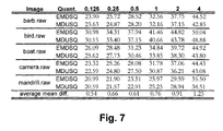
- Fig. 7 illustrates performance (PSNR) of the central reconstruction of MD-QT coding based on EMDSQ compared to the one based on MDUSQ for bit rates ranging from 0.125 to 4 bpp.
- Fig. 8 illustrates a transmission system according to an embodiment of the present invention, with at the transmitter side a plurality of quantizers for generating with different quantizations, from a source digital signal, a plurality of bit-streams, and with at the receiver side a plurality of dequantizers for generating, from at least partially received bit-streams, a plurality of inverse quantized bit-streams which may be combined to obtain a better approximation of the source signal.
- Fig. 9 illustrates a transmission system according to another embodiment of the present invention, with at the transmitter side a quantizer for generating with different quantizations, from a source digital signal, a plurality of bit-streams, and with at the receiver side a combined central dequantizer for generating, from at least partially received bit-streams, a combined inverse quantized bit-stream.
- Fig. 10 and 11 show implementations of embodiments of the present invention in computers and embedded processors.
- the present invention relates to data communication, more particularly to transmission of multiple bit-streams over a channel or over a plurality of channels, whereby each bit-stream in itself can reconstruct an approximation of the original data, for example an approximation of the original image if the source data is image data.
- the present invention does not require that all digital streams are used to create the original signal at a receiver.
- the more bit-streams that are received and combined with each other the better the reconstructed data, e.g. image is likely to be.
- Each, or at least a plurality, of the bit-streams are quantized in a different way.
- the process of the present invention is illustrated in Fig. 8 and in Fig. 9.
- a source digital signal S such as e.g. a source video signal (an image), or more generally any type of input data to be transmitted, is quantized in a quantizer Q, or in a plurality of quantizers Q 1 , Q 2 , ..., Q N , so as to form a number of N bit-streams S 1 , S 2 , ..., S N .
- the source signal can be a function of one or more continuous or discrete variables, and can itself be continuous or descrete-valued.
- Each of the generated N bit-streams S 1 , S 2 , ..., S N may or may not be encoded subsequently, for example, entropy encoded, in encoders C 1 , C 2 , ..., C N before transmitting them over a channel ⁇ .
- An encoder produces from the source signal a signal which is compatible with the channel.
- the channel is the physical medium that conducts the transmitted signal. After transmission over the channel the signals are received at a receiver or decoder side. A receiver or decoder attempts to recreate the message from the received signals.
- the received signals may be distorted or include deletions (e.g. caused by interference).
- the at least partially received signals P 1 , P 2 , ..., P N are inverse quantized or dequantized at the receiver side of the transmission system.
- the terms "inverse quantizing” and “dequantizing” have the same meaning, and one can be replaced by the other in the present document.
- the inverse quantization or dequantizing may be done in a separate dequantizer Q 1 -1 , Q 2 -1 , ..., Q N -1 for each bit-stream or in a single dequantizer for all the streams.
- Each inverse quantized signal can be used alone for displaying an approximation of the source digital signal, e.g. for displaying an approximation of a source image.
- At least two inverse quantized signals may be combined into an inverse quantized and combined signal which can be used e.g. for displaying a better approximation of the transmitted image.
- the inverse quantization or dequantizing may be done in a combined inverse quantizer, also leading to an inverse quantized and combined signal which can be used e.g. for displaying the transmitted image.
- EMDSQ For the quantizers of the present invention, EMDSQ, according to an embodiment the side quantizers Q m,p / S are non-uniform embedded quantizers, thus for any 0 ⁇ p ⁇ P there exist k,j , k ⁇ j such that L k # L j .
- the quantization intervals S 2,1 / -,1 and S 2,1 / +,1 of the second-channel embedded quantizer Q 2,1 / S are divided respectively into three quantization intervals S 2,0 / ⁇ 1,0, S 2,0 / ⁇ 1,1 and S 2,0 / ⁇ 1,2 of the higher rate quantizer G 2,0 / S .
- the dead zone S 2,1 / 0of the second-channel embedded quantizer Q 2,1 / S is not divided and is transformed into S 2,0 / 0,0 of S 2,0 / S .
- a uniform entropy-coded scalar quantizer is optimal for high rates, and nearly optimal for lower rates, as described in D. Taubman and M. W. Marcellin, JPEG2000 - Image Compression: Fundamentals, Standards and Practice, Hingham, MA: Kluwer Academic Publishers, 2001. Furthermore, the above book also describes that, for input data with symmetric probability density function (PDF), the rate-distortion behaviour at low rates can be improved by widening the quantization interval located around zero, that is, by using deadzone uniform scalar quantizers.
- PDF symmetric probability density function
- the rate-distortion function gives the minimum rate needed to approximate a source signal up to a given distortion.
- the central quantizer Q 1 / C and Q 0 / C obtained from the side quantizers Q 1,1 / S , Q 2,1 / S and Q 1,0 / S , Q 2,0 / S presented in Fig. 1 is a double-deadzone embedded quantizer, i.e. a quantizer having equal quantization intervals with a size or width ⁇ , except for the quantization interval around zero which has a size or width 2 ⁇ . Hence, it shows the above-mentioned characteristics of improved rate-distortion behaviour.
- M channel quantizers can only be formulated analytically, since it is not possible to graphically build an M-dimensional matrix to apply Vaishampayan's method.
- the quantization intervals of the side quantizers Q m ,0 / S , 1 ⁇ m ⁇ 4 are embedded respectively in the quantization intervals of the side quantizers Q m ,1 / S .
- the negative side of the quantizers is not illustrated, but is a mirrored version of the positive side which is shown.
- R 0 is the lowest rate needed by any SDC in order to achieve the central D 0 distortion of the MDC.
- the redundancy ranges from ( M -1) R 0 (the bit-stream is replicated over the M channels) to 0 (the data is totally uncorrelated over the M channels).
- FIG. 3 A graphic representation of the redundancy versus the number of channels, given by Eq. (8), is shown in Fig. 3.
- the theoretical boundary of the redundancy (M-1)R 0 is reached when the stream is replicated over M channels and is represented by the upper curve in the graph. It is noticeable that the redundancy between the channels monotonically decreases as the quantization level p increases.
- a proposed MD-QT coding system encodes the quantizers' output by using a customised version of the wavelet-based QT coding of the significance maps algorithm described in A. Sloanu, J. Cornelis, G. Van der Auwera, and P. Cristea, "Wavelet-based lossless compression scheme with progressive transmission capability," Int. J. Imaging Systems and Tech., vol. 10, no. 1, pp. 76-85, Jan. 1999.
- Any type of coding algorithm, and any type of input source such as for example special domain, wavelet transform or DCT transform, can be used.
- T p is denoted the significance threshold from a coding step corresponding to the quantization level p, 0 ⁇ p ⁇ P ; the significance of wavelet coefficients being recorded in a significance map with respect to the applied threshold T p .
- k (k 1 ,k 2 ) the spatial location of the wavelet coefficient from the wavelet transform matrix is denoted, where k 1 and k 2 stand for the row and column index, respectively.
- the significance operator ⁇ p determines the significance of a quadrant but not the significance of a coefficient.
- the significant operator ⁇ p is no longer applied, and instead, the quantizer index allocation operator, denoted by ⁇ (w( I )), is utilised.
- the EMDSQ by their structure present the particularity that different quantization intervals at quantization level p are divided into different numbers of quantization intervals at the quantization level p -1 as shown hereinabove.
- the wavelet coefficients have to be compared against the values of the boundary points of quantization intervals at a certain quantization level p. It is considered that an arbitrary quantization interval at level p will be divided into N quantization intervals at level p- 1.
- the index allocation operator ⁇ determines the codeword associated to each quantized coefficient as follows: where the boundary points are denoted as T ⁇ ,n , with 0 ⁇ n ⁇ N and T ⁇ , 0 ⁇ T ⁇ ,1 ⁇ ... ⁇ T ⁇ , N .
- T ⁇ ,n the boundary points
- T ⁇ ,n the boundary points
- the significance map Q p / b ( 0,V ) of the wavelet image w is split into four quadrants Q p / b ( k i , v /2), 1 ⁇ i ⁇ 4, each having half the original parent size or width, with k i indicating the origin of each quadrant.
- the descendent significant quadrants are then further spliced until the leaf nodes (i.e. wavelet coefficients) are isolated.
- the symbols S n (0 ⁇ n ⁇ N ) are allocated by applying the index allocation operator ⁇ ( w ( l )).
- the significance pass records the positions i of all the leaf nodes newly identified as significant, using a recursive tree structure of quadrants (or a quad-tree structure).
- the significance pass is restarted to update the entire quad-tree structure by identifying the new significant leaf nodes.
- the significance pass is restarted to update the entire quad-tree structure by identifying the new significant leaf nodes.
- the corresponding refinement pass is activated for the significant leaf nodes.
- the refinement pass is performed with respect to the corresponding refinement threshold T p,m / r .
- the coding passes performed by the proposed MD-QT coding system are the significance pass, employing the significance thresholds T p,m 0 ⁇ p ⁇ P , followed by the refinement pass, utilising the refinement thresholds T p,m / r , with m , 1 ⁇ m ⁇ 2 denoting the channel index for the case with two channels.
- Fig. 4 depicts the first channel EMDSQ with granular region ranging from 0 to 24 (x ⁇ [0,24)).
- the significance map coding is performed with respect to the set of thresholds T p ,1 with the rate of decay given by Eq. (12).
- the description of the quantizers reveals that half of the quantization intervals at level p are divided into three quantization intervals at level p -1, while the other half are not divided. Thus, three index allocation operators are considered.
- the purpose of the refinement pass is to perform the index allocation for coefficients that have already been coded as significant at the previous significance passes.
- the index allocation is performed with respect to the new updated values of the boundary points.
- the output of the MD-QT coder may further be entropy coded with an adaptive arithmetic coder, as described in 1.
- One model is used to encode the quadrant significance symbols.
- Another model is used for the sign symbol encoding.
- Another two models are utilised to entropy code the symbols generated by the index allocation operators ⁇ ( w ( I )) and ⁇ ( w ( I )) respectively. Since the MD-QT output for the quantization intervals that are not divided is represented by only one symbol S ⁇ ,1 , it is completely redundant to further encode these symbols.
- Fig. 5 shows that comparable results are obtained for the side channel(s) and that the EMDSQ of the present invention outperforms MDUSQ for the central channel. Similar experimental results were obtained varying the standard deviation within the range 12 ⁇ 90.
- the MDUSQ has been integrated in the MD-QT coding scheme, resulting into a common entropy-coding module for both types of quantizers.
- the results shown in Fig. 6 obtained on the Lena image reveal that on the central channel the EMDSQ outperforms MDUSQ with 0.52-1.08 dB.
- the results obtained on a common image data set given in the Table of Fig. 7 show that in comparison to the prior art MDUSQ, the EMDSQ of the present invention provides constantly better rate-distortion performances on the central channel for all the rates.
- Fig. 10 shows the implementation of a coder/decoder which can be used with the present invention implemented using a microprocessor 230 such as a Pentium IV from Intel Corp. USA, e.g. in a Personal Computer.
- the microprocessor 230 may have an optional element such as a co-processor 224, e.g. for arithmetic operations or microprocessor 230-224 may be a bit-sliced processor.
- a RAM memory 222 may be provided, e.g. DRAM.
- I/O (input/output) interfaces 225, 226, 227 may be provided, e.g. UART, USB, I 2 C bus interface as well as an I/O selector 228. These may serve to receive a source digital signal.
- FIFO buffers 232 may be used to decouple the processor 230 from data transfer through these interfaces.
- a keyboard and mouse interface 234 will usually be provided as well as a visual display unit interface 236.
- Access to an external memory such as a disk drive may be provided via an external bus interface 238 with address, data and control busses.
- the various blocks of the circuit are linked by suitable busses 231.
- the interface to the channel is provided by block 242 which can handle the encoded signals as well as transmitting to and receiving from the channel. Encoded data received by block 242 is passed to the processor 230 for processing.
- the circuit of Fig. 10 may be constructed as a VLSI chip around an embedded microprocessor 230 such as an ARM7TDMI core designed by ARM Ltd., UK which may be synthesized onto a single chip with the other components shown.
- a zero wait state SRAM memory 222 may be provided on-chip as well as an optional cache memory 224.
- Various I/O (input/output) interfaces 225, 226, 227 may be provided, e.g. UART, USB, I 2 C bus interface as well as an I/O selector 228.
- FIFO buffers 232 may be used to decouple the processor 230 from data transfer through these interfaces.
- a counter/timer block 234 may be provided as well as an interrupt controller 236.
- Access to an external memory may be provided an external bus interface 238 with address, data and control busses.
- the various blocks of the circuit are linked by suitable busses 231.
- the interface to the channel is provided by block 242 which can handle the encoded signals as well as transmitting to and receiving from the channel. Encoded data received by block 242 is passed to the processor 230 for processing.
- Software programs may be stored in an internal ROM (read only memory) 246.
- Software programs for carrying out coding and/or encoding, especially the quantising and dequantising in accordance with any of the methods of the present invention may also be stored on the system in executable form.
- software programs may be provided for quantising and dequantising according to embodiments of the present invention described above to be applied to blocks of data to generate two or more streams of encoded data.
- the software for executing on the processor 230 has code for carrying out the function of quantizing a source digital signal to generate with different quantizations at least a first and a second bit-stream, of which at least one bit-stream has been generated by an embedded quantization, transmitting at least one of the at least first and second bit-streams and generating a dequantized digital signal from at least parts of one of the transmitted at least first and second bit streams, whereby if in the generation of the dequantized digital signal the parts of the at least first and second bit-streams are combined, the combined dequantized signal is generated by an embedded dequantizer having at least two quantization levels and having at least one quantization interval at each quantization level which is finer than quantization intervals for dequantizing any of the at least first and second bit-streams.
- Code may be provided so that each quantization level has a quantization rate and at least one bit-stream generated by an embedded quantization is generated by an embedded quantization where at least two quantization intervals at lower quantization rate are split into a different number of quantization intervals at a higher quantization rate. Code may also be provided so that at least one bit-stream generated by an embedded quantization is generated by a non-uniform embedded quantization. Code may also be provided so that at least one bit-stream generated by a non-uniform embedded quantization is generated by a non-uniform embedded dead zone quantization. Code may be provided so that at least one bit-stream generated by a non-uniform embedded dead zone quantization is generated by a non-uniform embedded double dead zone quantization.
- NCode may be provided so that at least one bit-stream generated by an embedded quantization is generated by a uniform embedded quantization. Code may be provided so that at least one bit-stream generated by a uniform embedded quantization is generated by a uniform embedded dead zone quantization. Code may also be provided so that at least one bit-stream generated by a uniform embedded dead zone quantization is generated by a uniform embedded double dead zone quantization. each bit-stream is generated by an embedded quantization.
- the methods described above may be written as computer programs in a suitable computer language such as C and then compiled for the specific processor in the design.
- the software may be written in C and then compiled using the ARM C compiler and the ARM assembler.
- the present invention also includes a data carrier on which is stored executable code segments, which when executed on a processor such as 230 will execute any of the methods of the present invention, in particular will execute quantising and/or dequantising according to embodiments of the present invention described above to be applied to images.
- the data carrier may be any suitable data carrier such as diskettes (“floopy disks"), optical storage media such as CD-ROMs, DVD ROM's, tape drives, hard drives, etc. which are computer readable.
- Fig. 11 shows the implementation of a coder/decoder which can be used with the present invention implemented using an dedicated quantiser/dequantiser module.
- Reference numbers in Fig. 11 which are the same as the reference numbers in Fig. 10 refer to the same components - both in the microprocessor and the embedded core embodiments.
- Module 240 may be constructed as an accelerator card for insertion in a personal computer.
- the module 240 has means for carrying out signal coding and/or decoding according to embodiments of the present invention described above.
- coders and encoders may be implemented as a separate module 241, e.g. an ASIC (Application Specific Integrated Circuit) or an FPGA (Field Programmable Gate Array) having means for quantising and/or dequnatising according to embodiments of the present invention.
- ASIC Application Specific Integrated Circuit
- FPGA Field Programmable Gate Array
- a module 240 may be used which may be constructed as a separate module in a multi-chip module (MCM), for example or combined with the other elements of the circuit on a VLSI.
- MCM multi-chip module
- the module 240 has means for carrying out quantising and/or dequantising according to embodiments of the present invention.
- these qunatisers/dequantisers may be implemented as a separate module 241, e.g. an ASIC (Application Specific Integrated Circuit) or an FPGA (Field Programmable Gate Array) having means for quantising and/or dequantising according to embodiments of the present invention described above.
Landscapes
- Engineering & Computer Science (AREA)
- Theoretical Computer Science (AREA)
- Compression, Expansion, Code Conversion, And Decoders (AREA)
Priority Applications (3)
| Application Number | Priority Date | Filing Date | Title |
|---|---|---|---|
| EP20030447073 EP1465349A1 (fr) | 2003-03-31 | 2003-03-31 | Quantificateurs scalaires imbriqués pour description multiple dans le cadre de la transmission progressive d'images |
| US10/813,811 US7356085B2 (en) | 2003-03-31 | 2004-03-30 | Embedded multiple description scalar quantizers for progressive image transmission |
| EP04447082A EP1465350A3 (fr) | 2003-03-31 | 2004-03-31 | Quantificateurs scalaires intégrés à description multiple pour transmission progressive d'image |
Applications Claiming Priority (1)
| Application Number | Priority Date | Filing Date | Title |
|---|---|---|---|
| EP20030447073 EP1465349A1 (fr) | 2003-03-31 | 2003-03-31 | Quantificateurs scalaires imbriqués pour description multiple dans le cadre de la transmission progressive d'images |
Publications (1)
| Publication Number | Publication Date |
|---|---|
| EP1465349A1 true EP1465349A1 (fr) | 2004-10-06 |
Family
ID=32842915
Family Applications (1)
| Application Number | Title | Priority Date | Filing Date |
|---|---|---|---|
| EP20030447073 Withdrawn EP1465349A1 (fr) | 2003-03-31 | 2003-03-31 | Quantificateurs scalaires imbriqués pour description multiple dans le cadre de la transmission progressive d'images |
Country Status (2)
| Country | Link |
|---|---|
| US (1) | US7356085B2 (fr) |
| EP (1) | EP1465349A1 (fr) |
Cited By (17)
| Publication number | Priority date | Publication date | Assignee | Title |
|---|---|---|---|---|
| WO2006108736A1 (fr) * | 2005-04-11 | 2006-10-19 | France Telecom | Procédé et dispositif de quantification progressive, procédé et dispositif de quantification inverse, programmes informatiques, signal et support de données correspondants |
| US7801383B2 (en) | 2004-05-15 | 2010-09-21 | Microsoft Corporation | Embedded scalar quantizers with arbitrary dead-zone ratios |
| US7974340B2 (en) | 2006-04-07 | 2011-07-05 | Microsoft Corporation | Adaptive B-picture quantization control |
| US7995649B2 (en) | 2006-04-07 | 2011-08-09 | Microsoft Corporation | Quantization adjustment based on texture level |
| US8059721B2 (en) | 2006-04-07 | 2011-11-15 | Microsoft Corporation | Estimating sample-domain distortion in the transform domain with rounding compensation |
| US8130828B2 (en) | 2006-04-07 | 2012-03-06 | Microsoft Corporation | Adjusting quantization to preserve non-zero AC coefficients |
| US8184694B2 (en) | 2006-05-05 | 2012-05-22 | Microsoft Corporation | Harmonic quantizer scale |
| US8189933B2 (en) | 2008-03-31 | 2012-05-29 | Microsoft Corporation | Classifying and controlling encoding quality for textured, dark smooth and smooth video content |
| US8238424B2 (en) | 2007-02-09 | 2012-08-07 | Microsoft Corporation | Complexity-based adaptive preprocessing for multiple-pass video compression |
| US8243797B2 (en) | 2007-03-30 | 2012-08-14 | Microsoft Corporation | Regions of interest for quality adjustments |
| US8331438B2 (en) | 2007-06-05 | 2012-12-11 | Microsoft Corporation | Adaptive selection of picture-level quantization parameters for predicted video pictures |
| US8422546B2 (en) | 2005-05-25 | 2013-04-16 | Microsoft Corporation | Adaptive video encoding using a perceptual model |
| US8442337B2 (en) | 2007-04-18 | 2013-05-14 | Microsoft Corporation | Encoding adjustments for animation content |
| US8498335B2 (en) | 2007-03-26 | 2013-07-30 | Microsoft Corporation | Adaptive deadzone size adjustment in quantization |
| US8503536B2 (en) | 2006-04-07 | 2013-08-06 | Microsoft Corporation | Quantization adjustments for DC shift artifacts |
| US8897359B2 (en) | 2008-06-03 | 2014-11-25 | Microsoft Corporation | Adaptive quantization for enhancement layer video coding |
| CN113281716A (zh) * | 2021-03-16 | 2021-08-20 | 中国人民解放军战略支援部队信息工程大学 | 一种光子计数激光雷达数据去噪方法 |
Families Citing this family (10)
| Publication number | Priority date | Publication date | Assignee | Title |
|---|---|---|---|---|
| CA2394352C (fr) * | 1999-12-14 | 2008-07-15 | Cisco Technology, Inc. | Systeme et procede de decodage adaptatif d'un signal video avec coordination de l'attribution des ressources |
| PT2037412E (pt) * | 2002-05-02 | 2013-12-05 | Fraunhofer Ges Forschung | Método e disposição para a codificação e descodificação aritmética de estados binários e um programa de computador apropriado e correspondente suporte de memória legível por computador |
| ITTO20040780A1 (it) * | 2004-11-09 | 2005-02-09 | St Microelectronics Srl | Procedimento e sistema per il trattamento di segnali a descrizioni multiple, relativo prodotto informatico |
| ITTO20040781A1 (it) * | 2004-11-09 | 2005-02-09 | St Microelectronics Srl | Procedimento per adattare in modo dinamico il bit-rate di un segnale digitale alla larghezza di banda disponibile, relativi dispositivi e prodotto informatico corrispondente |
| US8620644B2 (en) * | 2005-10-26 | 2013-12-31 | Qualcomm Incorporated | Encoder-assisted frame loss concealment techniques for audio coding |
| US20070237237A1 (en) * | 2006-04-07 | 2007-10-11 | Microsoft Corporation | Gradient slope detection for video compression |
| WO2008104549A2 (fr) * | 2007-02-28 | 2008-09-04 | Fotonation Vision Limited | Séparation de variabilité d'éclairage directionnelle dans un modelage de visage statistique sur la base d'une décomposition spatiale de texture |
| WO2009045148A1 (fr) * | 2007-10-05 | 2009-04-09 | Telefonaktiebolaget L M Ericsson (Publ) | Procédé et appareil de codage par descriptions multiples |
| US8891630B2 (en) | 2011-10-24 | 2014-11-18 | Blackberry Limited | Significance map encoding and decoding using partition set based context assignment |
| EP2980793A1 (fr) | 2014-07-28 | 2016-02-03 | Fraunhofer-Gesellschaft zur Förderung der angewandten Forschung e.V. | Codeur, décodeur, système et procédés de codage et de décodage |
Family Cites Families (1)
| Publication number | Priority date | Publication date | Assignee | Title |
|---|---|---|---|---|
| US6611624B1 (en) * | 1998-03-13 | 2003-08-26 | Cisco Systems, Inc. | System and method for frame accurate splicing of compressed bitstreams |
-
2003
- 2003-03-31 EP EP20030447073 patent/EP1465349A1/fr not_active Withdrawn
-
2004
- 2004-03-30 US US10/813,811 patent/US7356085B2/en not_active Expired - Fee Related
Non-Patent Citations (5)
| Title |
|---|
| BRUNK H ET AL: "Fixed-rate successively refinable scalar quantizers", PROCEEDINGS DCC'96. DATA COMPRESSION CONFERENCE (CAT. NO.96TB100013), PROCEEDINGS OF DATA COMPRESSION CONFERENCE - DCC '96, SNOWBIRD, UT, USA, 31 MARCH-3 APRIL 1996, 1996, Los Alamitos, CA, USA, IEEE Comput. Soc. Press, USA, pages 250 - 259, XP002262852, ISBN: 0-8186-7358-3 * |
| GUIONNET T ET AL: "Embedded multiple description coding for progressive image transmission over unreliable channels", PROCEEDINGS 2001 INTERNATIONAL CONFERENCE ON IMAGE PROCESSING. ICIP 2001. THESSALONIKI, GREECE, OCT. 7 - 10, 2001, INTERNATIONAL CONFERENCE ON IMAGE PROCESSING, NEW YORK, NY: IEEE, US, vol. 1 OF 3. CONF. 8, 7 October 2001 (2001-10-07), pages 94 - 97, XP010564804, ISBN: 0-7803-6725-1 * |
| SERVETTO S D ET AL: "MULTIPLE DESCRIPTION WAVELET BASED IMAGE CODING", IEEE TRANSACTIONS ON IMAGE PROCESSING, IEEE INC. NEW YORK, US, vol. 9, no. 5, May 2000 (2000-05-01), pages 813 - 826, XP000958395, ISSN: 1057-7149 * |
| TANG B ET AL: "A perceptually based embedded subband speech coder", IEEE TRANSACTIONS ON SPEECH AND AUDIO PROCESSING, MARCH 1997, IEEE, USA, vol. 5, no. 2, pages 131 - 140, XP002262851, ISSN: 1063-6676 * |
| VINAY ANANT VAISHAMPAYAN: "DESIGN OF MULTIPLE DESCRIPTION SCALAR QUANTIZERS", IEEE TRANSACTIONS ON INFORMATION THEORY, IEEE INC. NEW YORK, US, vol. 39, no. 3, 1 May 1993 (1993-05-01), pages 821 - 834, XP000383024, ISSN: 0018-9448 * |
Cited By (27)
| Publication number | Priority date | Publication date | Assignee | Title |
|---|---|---|---|---|
| US7801383B2 (en) | 2004-05-15 | 2010-09-21 | Microsoft Corporation | Embedded scalar quantizers with arbitrary dead-zone ratios |
| WO2006108736A1 (fr) * | 2005-04-11 | 2006-10-19 | France Telecom | Procédé et dispositif de quantification progressive, procédé et dispositif de quantification inverse, programmes informatiques, signal et support de données correspondants |
| US8422546B2 (en) | 2005-05-25 | 2013-04-16 | Microsoft Corporation | Adaptive video encoding using a perceptual model |
| US8249145B2 (en) | 2006-04-07 | 2012-08-21 | Microsoft Corporation | Estimating sample-domain distortion in the transform domain with rounding compensation |
| US7974340B2 (en) | 2006-04-07 | 2011-07-05 | Microsoft Corporation | Adaptive B-picture quantization control |
| US7995649B2 (en) | 2006-04-07 | 2011-08-09 | Microsoft Corporation | Quantization adjustment based on texture level |
| US8059721B2 (en) | 2006-04-07 | 2011-11-15 | Microsoft Corporation | Estimating sample-domain distortion in the transform domain with rounding compensation |
| US8130828B2 (en) | 2006-04-07 | 2012-03-06 | Microsoft Corporation | Adjusting quantization to preserve non-zero AC coefficients |
| US8767822B2 (en) | 2006-04-07 | 2014-07-01 | Microsoft Corporation | Quantization adjustment based on texture level |
| US8503536B2 (en) | 2006-04-07 | 2013-08-06 | Microsoft Corporation | Quantization adjustments for DC shift artifacts |
| US8184694B2 (en) | 2006-05-05 | 2012-05-22 | Microsoft Corporation | Harmonic quantizer scale |
| US8588298B2 (en) | 2006-05-05 | 2013-11-19 | Microsoft Corporation | Harmonic quantizer scale |
| US9967561B2 (en) | 2006-05-05 | 2018-05-08 | Microsoft Technology Licensing, Llc | Flexible quantization |
| US8711925B2 (en) | 2006-05-05 | 2014-04-29 | Microsoft Corporation | Flexible quantization |
| US8238424B2 (en) | 2007-02-09 | 2012-08-07 | Microsoft Corporation | Complexity-based adaptive preprocessing for multiple-pass video compression |
| US8498335B2 (en) | 2007-03-26 | 2013-07-30 | Microsoft Corporation | Adaptive deadzone size adjustment in quantization |
| US8576908B2 (en) | 2007-03-30 | 2013-11-05 | Microsoft Corporation | Regions of interest for quality adjustments |
| US8243797B2 (en) | 2007-03-30 | 2012-08-14 | Microsoft Corporation | Regions of interest for quality adjustments |
| US8442337B2 (en) | 2007-04-18 | 2013-05-14 | Microsoft Corporation | Encoding adjustments for animation content |
| US8331438B2 (en) | 2007-06-05 | 2012-12-11 | Microsoft Corporation | Adaptive selection of picture-level quantization parameters for predicted video pictures |
| US8189933B2 (en) | 2008-03-31 | 2012-05-29 | Microsoft Corporation | Classifying and controlling encoding quality for textured, dark smooth and smooth video content |
| US8897359B2 (en) | 2008-06-03 | 2014-11-25 | Microsoft Corporation | Adaptive quantization for enhancement layer video coding |
| US9185418B2 (en) | 2008-06-03 | 2015-11-10 | Microsoft Technology Licensing, Llc | Adaptive quantization for enhancement layer video coding |
| US9571840B2 (en) | 2008-06-03 | 2017-02-14 | Microsoft Technology Licensing, Llc | Adaptive quantization for enhancement layer video coding |
| US10306227B2 (en) | 2008-06-03 | 2019-05-28 | Microsoft Technology Licensing, Llc | Adaptive quantization for enhancement layer video coding |
| CN113281716A (zh) * | 2021-03-16 | 2021-08-20 | 中国人民解放军战略支援部队信息工程大学 | 一种光子计数激光雷达数据去噪方法 |
| CN113281716B (zh) * | 2021-03-16 | 2023-08-08 | 中国人民解放军战略支援部队信息工程大学 | 一种光子计数激光雷达数据去噪方法 |
Also Published As
| Publication number | Publication date |
|---|---|
| US7356085B2 (en) | 2008-04-08 |
| US20050027521A1 (en) | 2005-02-03 |
Similar Documents
| Publication | Publication Date | Title |
|---|---|---|
| EP1465349A1 (fr) | Quantificateurs scalaires imbriqués pour description multiple dans le cadre de la transmission progressive d'images | |
| RU2417518C2 (ru) | Эффективное кодирование и декодирование блоков преобразования | |
| Kiely et al. | The ICER progressive wavelet image compressor | |
| JP2527874B2 (ja) | 局所的デ―タ損失に対する頑強性を圧縮化画像デ―タに付与するための装置 | |
| JP4755309B2 (ja) | データ圧縮 | |
| US6671416B2 (en) | Method for transmitting data using an embedded bit stream produced in a hierarchical table-lookup vector quantizer | |
| EP1494482B1 (fr) | Procédé pour le transcodage d'une image comprimée par JPEG2000 | |
| WO2003044964A1 (fr) | Procede de codage faisant appel a un code de longueur variable et procede de decodage faisant appel a un code de longueur variable | |
| JPH07112279B2 (ja) | 2次元情報の符号化システム | |
| Pradhan et al. | Enhancing analog image transmission systems using digital side information: A new wavelet-based image coding paradigm | |
| EP3864848A1 (fr) | Procédé et appareil de compression d'images | |
| US20030018647A1 (en) | System and method for data compression using a hybrid coding scheme | |
| EP1333679B1 (fr) | Compression de données | |
| JPH10304368A (ja) | 圧縮システム、圧縮方法、伸長システム、順変換装置、圧縮装置、符号化方法、符号化装置、集積回路、復号化装置、文脈モデル装置、圧縮実行方法、符号化システム、及び、変換係数処理方法 | |
| KR20020008133A (ko) | 유한 알파벳 데이터의 비손실 적응 인코딩 | |
| Guionnet et al. | Soft decoding of multiple descriptions. | |
| EP1465350A2 (fr) | Quantificateurs scalaires intégrés à description multiple pour transmission progressive d'image | |
| DK1504408T3 (en) | Arithmetic coding system and method | |
| Gavrilescu et al. | Embedded multiple description scalar quantizers for progressive image transmission | |
| Rissanen et al. | Coding and compression: A happy union of theory and practice | |
| Gavrilescu et al. | High-redundancy embedded multiple-description scalar quantizers for robust communication over unreliable channels | |
| Gavrilescu et al. | Embedded multiple description scalar quantizers and wavelet-based quadtree coding for progressive image transmission over unreliable channels | |
| Darragh et al. | Fixed distortion, variable rate subband coding of images | |
| Gavrilescu et al. | Scalable multiple-description image coding based on embedded quantization | |
| Jafarkhani | Wavelet coding of images: adaptation, scalability, and transmission over wireless channels |
Legal Events
| Date | Code | Title | Description |
|---|---|---|---|
| PUAI | Public reference made under article 153(3) epc to a published international application that has entered the european phase |
Free format text: ORIGINAL CODE: 0009012 |
|
| AK | Designated contracting states |
Kind code of ref document: A1 Designated state(s): AT BE BG CH CY CZ DE DK EE ES FI FR GB GR HU IE IT LI LU MC NL PT RO SE SI SK TR |
|
| AX | Request for extension of the european patent |
Extension state: AL LT LV MK RO |
|
| 17P | Request for examination filed |
Effective date: 20040917 |
|
| STAA | Information on the status of an ep patent application or granted ep patent |
Free format text: STATUS: THE APPLICATION HAS BEEN WITHDRAWN |
|
| 18W | Application withdrawn |
Effective date: 20041112 |