EP1465722B1 - Karbonisierungsvorrichtung mit zielkarbonisierungsausmass - Google Patents
Karbonisierungsvorrichtung mit zielkarbonisierungsausmass Download PDFInfo
- Publication number
- EP1465722B1 EP1465722B1 EP02805128A EP02805128A EP1465722B1 EP 1465722 B1 EP1465722 B1 EP 1465722B1 EP 02805128 A EP02805128 A EP 02805128A EP 02805128 A EP02805128 A EP 02805128A EP 1465722 B1 EP1465722 B1 EP 1465722B1
- Authority
- EP
- European Patent Office
- Prior art keywords
- tank
- water
- baffle
- level
- stream
- Prior art date
- Legal status (The legal status is an assumption and is not a legal conclusion. Google has not performed a legal analysis and makes no representation as to the accuracy of the status listed.)
- Expired - Lifetime
Links
Images



Classifications
-
- A—HUMAN NECESSITIES
- A23—FOODS OR FOODSTUFFS; TREATMENT THEREOF, NOT COVERED BY OTHER CLASSES
- A23L—FOODS, FOODSTUFFS OR NON-ALCOHOLIC BEVERAGES, NOT OTHERWISE PROVIDED FOR; PREPARATION OR TREATMENT THEREOF
- A23L2/00—Non-alcoholic beverages; Dry compositions or concentrates therefor; Preparation or treatment thereof
- A23L2/52—Adding ingredients
- A23L2/54—Mixing with gases
-
- B—PERFORMING OPERATIONS; TRANSPORTING
- B01—PHYSICAL OR CHEMICAL PROCESSES OR APPARATUS IN GENERAL
- B01F—MIXING, e.g. DISSOLVING, EMULSIFYING OR DISPERSING
- B01F23/00—Mixing according to the phases to be mixed, e.g. dispersing or emulsifying
- B01F23/20—Mixing gases with liquids
- B01F23/23—Mixing gases with liquids by introducing gases into liquid media, e.g. for producing aerated liquids
- B01F23/236—Mixing gases with liquids by introducing gases into liquid media, e.g. for producing aerated liquids specially adapted for aerating or carbonating beverages
- B01F23/2362—Mixing gases with liquids by introducing gases into liquid media, e.g. for producing aerated liquids specially adapted for aerating or carbonating beverages for aerating or carbonating within receptacles or tanks, e.g. distribution machines
-
- B—PERFORMING OPERATIONS; TRANSPORTING
- B01—PHYSICAL OR CHEMICAL PROCESSES OR APPARATUS IN GENERAL
- B01F—MIXING, e.g. DISSOLVING, EMULSIFYING OR DISPERSING
- B01F23/00—Mixing according to the phases to be mixed, e.g. dispersing or emulsifying
- B01F23/20—Mixing gases with liquids
- B01F23/23—Mixing gases with liquids by introducing gases into liquid media, e.g. for producing aerated liquids
- B01F23/237—Mixing gases with liquids by introducing gases into liquid media, e.g. for producing aerated liquids characterised by the physical or chemical properties of gases or vapours introduced in the liquid media
- B01F23/2376—Mixing gases with liquids by introducing gases into liquid media, e.g. for producing aerated liquids characterised by the physical or chemical properties of gases or vapours introduced in the liquid media characterised by the gas being introduced
- B01F23/23762—Carbon dioxide
- B01F23/237621—Carbon dioxide in beverages
-
- Y—GENERAL TAGGING OF NEW TECHNOLOGICAL DEVELOPMENTS; GENERAL TAGGING OF CROSS-SECTIONAL TECHNOLOGIES SPANNING OVER SEVERAL SECTIONS OF THE IPC; TECHNICAL SUBJECTS COVERED BY FORMER USPC CROSS-REFERENCE ART COLLECTIONS [XRACs] AND DIGESTS
- Y10—TECHNICAL SUBJECTS COVERED BY FORMER USPC
- Y10S—TECHNICAL SUBJECTS COVERED BY FORMER USPC CROSS-REFERENCE ART COLLECTIONS [XRACs] AND DIGESTS
- Y10S261/00—Gas and liquid contact apparatus
- Y10S261/07—Carbonators
Definitions
- the invention relates to a system for mixing water with carbon dioxide (CO 2 ), for example, CO 2 gas, to produce carbonated water and, more specifically, to a carbonator with a targeted carbonation level for use in, for example, a post-mix beverage dispenser.
- CO 2 carbon dioxide
- Some conventional carbonators used, for example, in post-mix beverage dispensers include a tank having a plain water inlet and a soda water outlet. These conventional carbonators may also include a supply of CO 2 that mixes with the plain water, resulting in carbonated water, or soda water. The soda water may be mixed with a syrup, or concentrate, and supplied to a dispensing nozzle associated with the post-mix beverage dispenser upon the demand of a user.
- a stream of plain water may be directed through the inlet and into a level of water existent in the tank in an effort to generate carbonated water.
- the impact of the stream of water with the water in the tank may cause undesirably high CO 2 volumes to develop in the tank.
- the water in the tank may be carbonated above desired levels, leading to valve sputtering and excessive foaming when dispensing a beverage.
- desired carbonation levels may not be maintained when the level of water in the tank reaches lower levels.
- the stream of water may not entrain a desired amount of CO 2 when the level of water is low and/or a lack of mixing/agitation of the water in the tank may result in low carbonation levels of the water in the tank.
- GB-A-15660753 and US 2735665 disclose an apparatus as set out in the preamble to claim 1
- an apparatus for mixing water with CO 2 to produce carbonated water at a targeted carbonation level comprising:
- a carbonator for use in a beverage dispenser may comprise a tank having a first end and a second end.
- An inlet in the second end of the tank may be configured to receive a supply of CO 2 .
- a method of mixing water with CO 2 to produce carbonated water at a targeted carbonation level comprising:
- Figure 1 is an exploded view of a carbonator in accordance with an exemplary embodiment of the invention
- Figure 2 is an end view of the carbonator of FIG. 1 ;
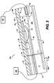
- FIG. 3 is a schematic and diagrammatic view of a dispenser system in accordance with an exemplary embodiment of the invention.
- Figure 4 is a sectional view of a carbonator in accordance with another exemplary aspect of the invention.
- a carbonator 10 for use in, for example, a post-mix beverage dispenser is provided.
- a carbonator 10 may include a tank 12 having a first end wall 14 and a second, opposite end wall 16.
- the tank 12 may be, for example, generally-cylindrical.
- the tank 12 may have, for example, a circular cross-section.
- the tank 12 may have a non-circular cross-section, for example, oval, elliptical, square, triangular, or the like.
- the carbonator 10 includes a baffle 20 in the tank 12.
- the baffle 20 is positioned between the first end wall 14 and the second end wall 16, dividing the tank into a first chamber 15 and a second chamber 17 fluidly connected to one another.
- the baffle 20 may include one or more openings 22, 24, 26 and/or a cut-out region 28.
- the baffle 20 may comprise a substantially flat, plate-like member having a shape that is generally complementary to at least a portion of the cross-section of the tank 12.
- the baffle 20 may be arranged substantially perpendicular to a substantially-central, longitudinal axis 13 of the tank 12 extending from the first end wall 14 to the second end wall 16.
- the baffle 20 may be smaller than the cross-section of the tank 12 so as to allow fluid communication between the first chamber 15 and the second chamber 17.
- the baffle 20 may be coupled to the tank 12 by, for example, spot-welding an outer periphery 21 of the baffle 20 to an inner surface 11 of the tank 12.
- the outer periphery 21 of the baffle 20 may include notches (not shown) to provide fluid communication between the first chamber 15 and the second chamber 17.
- the baffle 20 may be disposed at a non-perpendicular angle with respect to the longitudinal axis 13 of the tank 12.
- the baffle 20 may not be shaped complementary to the cross-section of the tank 12. For example, if the tank 12 has a circular cross-section and the baffle 20 is not perpendicular to the longitudinal axis 13, the baffle 20 may have an elliptical shape.
- the carbonator 10 includes an opening 30 at the first end wall 14 of the tank 12 configured to receive a flow of water.
- the opening 30 is configured as an orifice 32 structured and arranged to direct the flow of water toward the baffle 20.
- An outlet 34 is positioned at the first end wall 14 of the tank 12.
- the opening 22 may accommodate a CO2 inlet member 40
- the opening 24 may accommodate a CO2 pressure relief outlet member 42
- the opening 26 may accommodate a probe housing 44.
- the inlet and outlet members 40,42 may be configured, for example, as tubular members extending from the second end wall 16 of the tank 12 toward the first end wall 14.
- the tubular members may each have an angled free end, as shown in FIG. 1 .
- the probe housing 44 may extend from the second end wall 16 of the tank 12 to the baffle 20. Alternatively, the probe housing 44 may extend from the second end wall 16 beyond the baffle 20, as shown in FIG. 4 .
- the probe housing 44 may house at least a portion of a liquid level probe 46 extending from the second end wall 16 of the tank 12 toward the first end wall 14.
- the liquid level probe 46 may include a high level sensor 48, a low level sensor 50, and a ground 52. It should be appreciated that the liquid level probe 46 may be configured in any known manner, including with or without a ground.
- the probe housing 44 and the liquid level probe 46 may be coupled by a keyed arrangement 56 to ensure proper alignment of the liquid level problem within the tank 12.
- the baffle 20 may be coupled, for example, by spot-welding, to the probe housing 44.
- the baffle 20 may also be adjustably coupled to the probe housing 44 in any known manner such that the baffle 20 may be adjustably positioned at any position along the probe housing 44 to target a desired carbonation level.
- the carbonator 10 may include an outlet member 54, for example, an outlet tube, extending from the outlet 34 into the tank 12.
- the outlet member 54 may extend beyond the baffle 20 through the cut-out region 28.
- the cut-out region 28 may be configured as a chord of the baffle 20 or any other configuration arranged to accommodate the outlet member 54.
- the outlet member 54 may provide fluid communication between the tank 12 and a customer interface (not shown).
- the CO2 inlet member 40, the CO2 pressure relief outlet member 42, the probe housing 44, and/or the liquid level probe 46 may extend from the first end wall 14 of the tank 12. It should also be appreciated that the opening 30, the orifice 32, the outlet 34, and/or the outlet member 54 may be disposed at the second end wall 16 of the tank 12.
- a beverage system 100 may include a carbonator 10 according to any of the above embodiments.
- the system includes a supply of liquid, for example, a water supply 180, and a CO2 supply 182.
- the carbonator 10 may be associated with a cold plate 184 configured to chill the contents of the tank 12 to a desired temperature.
- the tank 12 may be arranged at an ' angle 186, for example, an acute angle, with respect to the cold plate 184 and/or a support surface 188.
- the support surface 188 may be the ground and the cold plate 184 may be substantially parallel to the ground.
- the angle 186 may be, for example, approximately 10°.
- the tank 12 may include a liquid 190, for example, water.
- the water may comprise carbonated water (i.e., soda water) for use in a post-mix beverage dispenser (i.e., a fountain dispenser).
- a post-mix beverage dispenser i.e., a fountain dispenser
- the arrangement of the tank 12 at the angle 186 provides a surface level 192 of the liquid 190 in the tank forming the same angle 186 with respect to the longitudinal axis of the tank 12.
- the tank 12 may contain a headspace 194 above the surface level 192 of the liquid 190.
- the liquid 190 and the headspace 194 may define a liquid-gas interface 195.
- the system 100 may also include a drink nozzle 196 at the customer interface configured to dispense, for example, a beverage.
- a flow of water is provided from the water supply 180 to the opening 30.
- the orifice 32 directs a stream of water through the headspace 194, into the liquid 190, and against the baffle 20.
- the orifice 32 may be structured and arranged such that the flow of water entrains CO2 bubbles while being injected into the liquid 190 to achieve a desired carbonation level of the liquid 190.
- the configuration, for example, the size, shape, location, and the like, of the orifice 32 may be modified to achieve the desired carbonation level.
- the CO2 inlet member 40 may provide fluid communication between the CO2 supply 182 and the headspace 194 of the tank 12, and the pressure relief member 184 may prevent over-pressurization of the headspace 194 and, in turn, the liquid 190.
- the baffle 20 is arranged and positioned in the tank 12 so as to achieve a desired carbonation level. That is, the baffle 20 may be moved to different positions along the longitudinal axis 13 to target different desired carbonation levels. The different positions of the baffle 20 vary the ratio between the size of the first chamber 15 and the size of the second chamber 17.
- the baffle 20 may be arranged such that the relatively larger size CO2 bubbles will remain in the first chamber (or whatever side of the baffle 20 receives the stream of water from the orifice 32).
- Some smaller CO2 bubbles may flow past the baffle 20, but may be absorbed into the liquid 190 before flowing into the outlet member 54: Any CO2 bubbles that may escape into the outlet member 54 will not generally result in valve sputtering at the drink nozzle 196 of the customer interface and/or excessive foaming in the beverage
- the baffle 20 may also be positioned in the tank 12 and configured such that when the surface level 192 of the liquid 190 drops to a certain level, the stream of water from the orifice 32 impacts the baffle 20 in a manner that atomizes the stream of water into smaller droplets. As a result, the targeted desired carbonation level may be more readily achieved.
- the baffle 20 may also be positioned in the tank 12 and configured such that when the surface level 192 of the liquid 190 drops to or below a level associated with the low level sensor 50, surfaces of the baffle 20 may agitate the liquid 190 to maintain the desired carbonation level. Consequently, the resulting beverage may be more properly carbonated regardless of the surface level 192 of liquid 190 in the tank 12.
- the liquid level probe 46 may operate in a well-known manner.
- the high level sensor 48 may detect when the level 192 of liquid 190 in the tank 12 reaches a first predetermined level and the low level sensor 50 may detect when the level 192 of liquid 190 reaches a second predetermined level.
- the high level sensor 48 may send a signal to a controller (not shown), which, in turn, controls operation of a valving device (not shown), for example, a control valve, and/or a pump (not shown) to stop the flow of water into the tank 12.
- the low level sensor 50 may send a signal to the controller, which, in turn, controls operation of the valving device and/or the pump to supply a flow of water to the tank 12.
- the outlet member 36 provides fluid communication between the tank 12 and the drink nozzle via the outlet.
- the carbonated water from the tank 12 may be mixed with a syrup, or concentrate, from one or more syrup supplies (not shown) according to a request from, for example, a user interface to form a drink desired by a consumer.
- the beverage dispenser may include a controller (not shown) that processes the request, activates a pump (not shown) to draw carbonated water from the tank, and determines the ratio of syrup to carbonated water.
- the drink may be dispensed through the drink nozzle associated with the beverage dispenser.
Landscapes
- Chemical & Material Sciences (AREA)
- Chemical Kinetics & Catalysis (AREA)
- Food Science & Technology (AREA)
- Nutrition Science (AREA)
- Life Sciences & Earth Sciences (AREA)
- Engineering & Computer Science (AREA)
- Health & Medical Sciences (AREA)
- Polymers & Plastics (AREA)
- Devices For Dispensing Beverages (AREA)
- Pharmaceuticals Containing Other Organic And Inorganic Compounds (AREA)
- Medicines Containing Plant Substances (AREA)
- Saccharide Compounds (AREA)
- Non-Alcoholic Beverages (AREA)
Claims (14)
- Vorrichtung zum Mischen von Wasser mit CO2, um kohlensäurehaltiges Wasser bei einem Zielkarbonisierungsniveau zu erzeugen, wobei die Vorrichtung umfasst:einen Behälter (12) mit mindestens einer Wand, wobei der Behälter (12) konfiguriert ist, um Wasser (190) zu enthalten, wobei bei Gebrauch der Behälter (12) Wasser (190) und einen Kopfraum (194) enthält und wobei der Behälter (12) ein erstes Ende (14) und ein zweites Ende (16) aufweist;einen Einlass in der mindestens einen Wand des Behälters (12), der konfiguriert ist, um eine Zufuhr von CO2 aufzunehmen;wobei die Zufuhr von CO2 in Fluidverbindung mit dem Kopfraum steht;ein Prallblech (20) im Behälter (12), das vom Einlass beabstandet ist und zwischen dem ersten Ende (14) und dem zweiten Ende (16) des Behälters (12) räumlich angeordnet ist;einen Auslass (34) am ersten Ende des Behälters; undeine Durchgangsöffnung (32) in der mindestens einen Wand des Behälters (12), wobei sich die Durchgangsöffnung (32) im ersten Ende (14) des Behälters (12) befindet; und eine Zufuhr von Wasser mit der Durchgangsöffnung (32) gekoppelt ist, wobei die Durchgangsöffnung (32) strukturiert und angeordnet ist, um einen Strom von Wasser in den Behälter (12) zu lenken,wobei das Prallblech (20) im Behälter (12) so positioniert ist, dass ein gewünschtes Karbonisierungsniveau des Wassers im Behälter angestrebt wird,
dadurch gekennzeichnet, dass entweder der Behälter (12) angeordnet ist, um bei einem spitzen Winkel (186) in Bezug zu einer Stützfläche (188) verwendet zu werden, oder das Prallblech unter einem nichtsenkrechten Winkel in Bezug zu einer Längsachse (13) des Behälters angeordnet ist, so dass die Wasseroberfläche unter einem Winkel zum Prallblech in Gebrauch vorliegt. - Vorrichtung nach Anspruch 1, wobei die Vorrichtung eine Karbonisierungsvorrichtung zur Verwendung bei einer Getränkeabgabeeinrichtung ist.
- Vorrichtung nach Anspruch 2, weiter umfassend ein Auslassrohr (54), das sich vom ersten Ende vorbei am Prallblech (20) erstreckt, wobei das Prallblech (20) einen Ausschnittsbereich umfasst, der strukturiert und angeordnet ist, um das Auslassrohr aufzunehmen.
- Vorrichtung nach Anspruch 2 oder 3, weiter umfassend ein CO2-Einlasselement (40) und ein Druckentlastungselement (42), die sich jeweils vom zweiten Ende (16) durch das Prallblech (20) erstrecken, wobei das Prallblech (20) mindestens eine Öffnung umfasst, die konfiguriert ist, um mindestens eines von dem CO2-Einlasselement (40) und dem Druckentlastungselement (42) aufzunehmen.
- Vorrichtung nach einem der Ansprüche 2 bis 4, weiter umfassend:ein Sensorgehäuse (44), das sich vom zweiten Ende (16) des Behälters (12) in Richtung auf das Prallblech (20) erstreckt; undeinen Flüssigkeitsniveausensor (46) im Sensorgehäuse (44), wobei sich der Flüssigkeitsniveausensor (46) durch das Prallblech (20) und in Richtung auf das erste Ende (14) erstreckt, wobei das Prallblech (20) mit dem Sensorgehäuse (44) gekoppelt ist und eine Öffnung umfasst, die strukturiert und angeordnet ist, um den Flüssigkeitsniveausensor (46) aufzunehmen, wobei sich das Sensorgehäuse (44) durch die Öffnung im Prallblech (20) und in Richtung auf das erste Ende (14) des Behälters (12) erstreckt.
- Vorrichtung nach einem der Ansprüche 1 bis 5, bei der das Prallblech (20) strukturiert und angeordnet ist, um den Strom von Wasser zu zerstäuben, wenn das Niveau des kohlensäurehaltigen Wassers ein vorbestimmtes niedriges Niveau erreicht.
- Vorrichtung nach einem der Ansprüche 1 bis 6, bei der das Prallblech (20) strukturiert und angeordnet ist, um kohlensäurehaltiges Wasser in Bewegung zu versetzen, das nahe beim Prallblech (20) fließt, wenn das Niveau des kohlensäurehaltigen Wassers ein vorbestimmtes niedriges Niveau erreicht.
- Vorrichtung nach einem der Ansprüche 1 bis 9, bei der die Durchgangsöffnung (32) konfiguriert ist, um den Strom von Wasser zu lenken, so dass CO2-Blasen mitgeschleppt werden, um das Zielkarbonisierungsniveau des Wassers zu erzeugen.
- Vorrichtung nach einem vorangehenden Anspruch, bei der das Prallblech (20) mit einem oder dem Sensorgehäuse (44) einstellbar gekoppelt ist, so dass das Prallblech einstellbar positioniert werden kann, um das gewünschte Karbonisierungsniveau anzustreben.
- Verfahren zum Mischen von Wasser mit CO2, um kohlensäurehaltiges Wasser bei einem Zielkarbonisierungsniveau zu erzeugen, wobei das Verfahren umfasst:Zuführen von gasförmigem CO2 zu einem Kopfraum in einem Behälter (12), der ein Volumen von zu karbonisierendem Wasser enthält, wobei der Kopfraum über einer Flüssigkeits-Gas-Grenzfläche zwischen dem Wasser und dem gasförmigen CO2 angeordnet ist;Lenken eines Stroms von Wasser zuerst durch den Kopfraum, um CO2-Gas darin mitzuschleppen, und dann in das Volumen von Wasser, um dasselbe auf ein gewünschtes Karbonisierungsniveau zu karbonisieren;Separieren von CO2-Blasen, die in der Wassermenge gebildet werden, entsprechend verhältnismäßig großen und kleinen Größen; undBereitstellen eines Prallblechs (2) im Behälter (12), wobei das Prallblech zwischen einem ersten Ende (14) und einen zweiten Ende (16) des Behälters (12) räumlich angeordnet ist;dadurch gekennzeichnet, dass entweder der Behälter (12) unter einem spitzen Winkel (186) in Bezug zu einer Stützfläche (184) angeordnet wird, oder das Prallblech unter einem nichtsenkrechten Winkel in Bezug zu einer Längsachse (13) des Behälters angeordnet wird, so dass die Flüssigkeits-Gas-Grenzfläche unter einem Winkel zum Prallblech vorliegt.
- Verfahren nach Anspruch 10, weiter umfassend: Zerstäuben eines Stroms von Wasser, wenn die Wassermenge im Behälter (12) ein vorbestimmtes Niveau erreicht.
- Verfahren nach Anspruch 10 oder 11, weiter umfassend: In-Bewegung-Versetzen von Wasser, während es von der Stromseite eines Prallblechs (20), das CO2-Blasen separiert, zur Kohlensäurewasserseite des Prallblechs (20) fließt, wenn die Wassermenge im Behälter (12) ein vorbestimmtes Niveau erreicht.
- Verfahren nach Anspruch-10, 11 oder 12, weiter umfassend: Einstellen einer Position des Prallblechs (20), das CO2-Blasen separiert, um ein gewünschtes Karbonisierungsniveau des Wassers im Behälter (12) anzustreben.
- Verfahren zum Abgeben eines Getränks, umfassend:Erzeugen von kohlensäurehaltigem Wasser gemäß dem Verfahren nach einem der Ansprüche 10 bis 13; Mischen einer Menge von Konzentrat mit einer Menge des kohlensäurehaltigen Wassers, um ein Getränk zu erzeugen; undAbgeben des Getränks.
Applications Claiming Priority (3)
| Application Number | Priority Date | Filing Date | Title |
|---|---|---|---|
| US10/015,584 US6767009B2 (en) | 2001-12-17 | 2001-12-17 | Carbonator with targeted carbonation level |
| US15584 | 2001-12-17 | ||
| PCT/US2002/039904 WO2003051499A2 (en) | 2001-12-17 | 2002-12-17 | Carbonator with targeted carbonation level |
Publications (2)
| Publication Number | Publication Date |
|---|---|
| EP1465722A2 EP1465722A2 (de) | 2004-10-13 |
| EP1465722B1 true EP1465722B1 (de) | 2009-03-25 |
Family
ID=21772286
Family Applications (1)
| Application Number | Title | Priority Date | Filing Date |
|---|---|---|---|
| EP02805128A Expired - Lifetime EP1465722B1 (de) | 2001-12-17 | 2002-12-17 | Karbonisierungsvorrichtung mit zielkarbonisierungsausmass |
Country Status (7)
| Country | Link |
|---|---|
| US (1) | US6767009B2 (de) |
| EP (1) | EP1465722B1 (de) |
| AT (1) | ATE426451T1 (de) |
| AU (1) | AU2002357200A1 (de) |
| DE (1) | DE60231748D1 (de) |
| ES (1) | ES2324652T3 (de) |
| WO (1) | WO2003051499A2 (de) |
Families Citing this family (10)
| Publication number | Priority date | Publication date | Assignee | Title |
|---|---|---|---|---|
| US7175164B2 (en) * | 2004-02-12 | 2007-02-13 | Lancer Partnership, Ltd | Method and apparatus for an oval carbonator |
| US20060288874A1 (en) * | 2005-06-24 | 2006-12-28 | The Coca-Cola Compay | In-Line, Instantaneous Carbonation System |
| US8177197B1 (en) | 2009-04-29 | 2012-05-15 | Natura Water, Inc. | Continuous carbonation apparatus and method |
| US8567767B2 (en) | 2010-05-03 | 2013-10-29 | Apiqe Inc | Apparatuses, systems and methods for efficient solubilization of carbon dioxide in water using high energy impact |
| CN105813974B (zh) * | 2013-12-26 | 2019-12-10 | 可口可乐公司 | 用于饮料分配器的冷却系统以及冷却系统的维护方法 |
| CA2965136A1 (en) * | 2014-10-20 | 2016-04-28 | Bedford Systems Llc | Flow circuit for carbonated beverage machine |
| CN111818808A (zh) * | 2018-01-08 | 2020-10-23 | 成就变革实验室有限公司 | 定制饮料制作装置、系统和方法 |
| CN112386110B (zh) * | 2020-11-30 | 2024-09-03 | 江门市伊科迈特电子科技有限公司 | 一种气泡水制造机 |
| CN112353251A (zh) * | 2020-11-30 | 2021-02-12 | 江门市伊科迈特电子科技有限公司 | 一种压力水壶 |
| CN114669447A (zh) * | 2022-04-25 | 2022-06-28 | 京东方科技集团股份有限公司 | 涂布设备的缓冲装置和涂布设备 |
Family Cites Families (14)
| Publication number | Priority date | Publication date | Assignee | Title |
|---|---|---|---|---|
| US2735665A (en) | 1956-02-21 | lance | ||
| US2271896A (en) | 1940-04-27 | 1942-02-03 | Harry H Lewis | Carbonator |
| US3109873A (en) * | 1959-09-08 | 1963-11-05 | William E Hotchkiss | Gas absorption apparatus |
| US3637197A (en) * | 1968-01-12 | 1972-01-25 | James L Hudson | Gas charger for liquids |
| GB1560753A (en) | 1977-03-08 | 1980-02-06 | British Syphon Ind Ltd | Carbonators |
| GB2052713B (en) | 1979-06-20 | 1984-02-29 | Booth Dispensers | Refrigeration system for drink dispensing machine |
| US4764315A (en) * | 1987-08-12 | 1988-08-16 | Ionics, Incorporated | Water cooler and carbonator |
| US5002201A (en) * | 1988-09-14 | 1991-03-26 | Aquatec Inc. | Bottled water cooler apparatus and method |
| US5417147A (en) * | 1994-02-02 | 1995-05-23 | Mason; Thomas | Apparatus for carbonating liquids at municipal water pressure |
| KR100199313B1 (ko) * | 1995-05-30 | 1999-06-15 | 다카노 야스아키 | 탄산수 제조 장치 |
| US5736072A (en) * | 1995-10-17 | 1998-04-07 | Sanden Corporation | Device for producing carbonated water |
| US5792391A (en) * | 1995-12-07 | 1998-08-11 | Imi Cornelius Inc. | Carbonator |
| US5855296A (en) | 1996-11-07 | 1999-01-05 | Mccann; Gerald P. | Combined carbonator and water pressure booster apparatus |
| US6652893B2 (en) * | 2001-07-09 | 2003-11-25 | William Berson | Machine and process for aerating and flavoring water |
-
2001
- 2001-12-17 US US10/015,584 patent/US6767009B2/en not_active Expired - Lifetime
-
2002
- 2002-12-17 AU AU2002357200A patent/AU2002357200A1/en not_active Abandoned
- 2002-12-17 DE DE60231748T patent/DE60231748D1/de not_active Expired - Lifetime
- 2002-12-17 ES ES02805128T patent/ES2324652T3/es not_active Expired - Lifetime
- 2002-12-17 WO PCT/US2002/039904 patent/WO2003051499A2/en not_active Ceased
- 2002-12-17 AT AT02805128T patent/ATE426451T1/de not_active IP Right Cessation
- 2002-12-17 EP EP02805128A patent/EP1465722B1/de not_active Expired - Lifetime
Also Published As
| Publication number | Publication date |
|---|---|
| ATE426451T1 (de) | 2009-04-15 |
| WO2003051499A2 (en) | 2003-06-26 |
| WO2003051499A3 (en) | 2003-10-30 |
| DE60231748D1 (de) | 2009-05-07 |
| AU2002357200A8 (en) | 2003-06-30 |
| US20030111745A1 (en) | 2003-06-19 |
| AU2002357200A1 (en) | 2003-06-30 |
| US6767009B2 (en) | 2004-07-27 |
| ES2324652T3 (es) | 2009-08-12 |
| EP1465722A2 (de) | 2004-10-13 |
Similar Documents
| Publication | Publication Date | Title |
|---|---|---|
| EP1460029B1 (de) | Vorrichtung zum Spenden von Flüssigkeit | |
| US5310088A (en) | Bottled water station for dispensing carbonated and uncarbonated water | |
| EP0675071B1 (de) | Getränke-Abgabevorrichtung | |
| US5000357A (en) | Soft drink dispenser | |
| US6935624B2 (en) | Carbonation system and method | |
| US11612864B2 (en) | Apparatuses for mixing gases into liquids | |
| US6767009B2 (en) | Carbonator with targeted carbonation level | |
| US10477883B2 (en) | Gas injection assemblies for batch beverages having spargers | |
| US11679397B2 (en) | Beverage dispensing nozzle | |
| EA022042B1 (ru) | Устройство для выдачи напитков с устройством для охлаждения воды | |
| GB2246523A (en) | Carbonation apparatus | |
| EP0676730B1 (de) | Getränkeautomat | |
| EP0873966A1 (de) | Karbonisierungssystem | |
| JP3540516B2 (ja) | マルチバルブ清涼飲料ディスペンサ | |
| EP1720631B1 (de) | Karbonator sowie verfahren zur erhöhung der oberfläche einer flüssigkeit zum vermischen mit einem gas | |
| JP7787327B2 (ja) | 炭酸飲料ディスペンサ | |
| JPH0150446B2 (de) | ||
| US7048147B2 (en) | Liquid dispensing device | |
| GB2269761A (en) | Post-mix dispense nozzle | |
| RU197658U1 (ru) | Устройство для смешивания жидкости и газа | |
| US20260109920A1 (en) | Static solution | |
| US20240207796A1 (en) | Module for continuously generating high-level carbonated water and method for continuously dispensing high-level carbonated water using the same | |
| WO2026035496A1 (en) | Systems and methods for carbonating and dispensing a beverage |
Legal Events
| Date | Code | Title | Description |
|---|---|---|---|
| PUAI | Public reference made under article 153(3) epc to a published international application that has entered the european phase |
Free format text: ORIGINAL CODE: 0009012 |
|
| 17P | Request for examination filed |
Effective date: 20040719 |
|
| AK | Designated contracting states |
Kind code of ref document: A2 Designated state(s): AT BE BG CH CY CZ DE DK EE ES FI FR GB GR IE IT LI LU MC NL PT SE SI SK TR |
|
| AX | Request for extension of the european patent |
Extension state: AL LT LV MK RO |
|
| 17Q | First examination report despatched |
Effective date: 20070202 |
|
| GRAP | Despatch of communication of intention to grant a patent |
Free format text: ORIGINAL CODE: EPIDOSNIGR1 |
|
| GRAS | Grant fee paid |
Free format text: ORIGINAL CODE: EPIDOSNIGR3 |
|
| GRAA | (expected) grant |
Free format text: ORIGINAL CODE: 0009210 |
|
| AK | Designated contracting states |
Kind code of ref document: B1 Designated state(s): AT BE BG CH CY CZ DE DK EE ES FI FR GB GR IE IT LI LU MC NL PT SE SI SK TR |
|
| REG | Reference to a national code |
Ref country code: GB Ref legal event code: FG4D |
|
| REG | Reference to a national code |
Ref country code: CH Ref legal event code: EP |
|
| REG | Reference to a national code |
Ref country code: IE Ref legal event code: FG4D |
|
| REF | Corresponds to: |
Ref document number: 60231748 Country of ref document: DE Date of ref document: 20090507 Kind code of ref document: P |
|
| PG25 | Lapsed in a contracting state [announced via postgrant information from national office to epo] |
Ref country code: FI Free format text: LAPSE BECAUSE OF FAILURE TO SUBMIT A TRANSLATION OF THE DESCRIPTION OR TO PAY THE FEE WITHIN THE PRESCRIBED TIME-LIMIT Effective date: 20090325 Ref country code: SI Free format text: LAPSE BECAUSE OF FAILURE TO SUBMIT A TRANSLATION OF THE DESCRIPTION OR TO PAY THE FEE WITHIN THE PRESCRIBED TIME-LIMIT Effective date: 20090325 |
|
| REG | Reference to a national code |
Ref country code: ES Ref legal event code: FG2A Ref document number: 2324652 Country of ref document: ES Kind code of ref document: T3 |
|
| PG25 | Lapsed in a contracting state [announced via postgrant information from national office to epo] |
Ref country code: AT Free format text: LAPSE BECAUSE OF FAILURE TO SUBMIT A TRANSLATION OF THE DESCRIPTION OR TO PAY THE FEE WITHIN THE PRESCRIBED TIME-LIMIT Effective date: 20090325 Ref country code: SE Free format text: LAPSE BECAUSE OF FAILURE TO SUBMIT A TRANSLATION OF THE DESCRIPTION OR TO PAY THE FEE WITHIN THE PRESCRIBED TIME-LIMIT Effective date: 20090625 |
|
| NLV1 | Nl: lapsed or annulled due to failure to fulfill the requirements of art. 29p and 29m of the patents act | ||
| PG25 | Lapsed in a contracting state [announced via postgrant information from national office to epo] |
Ref country code: BE Free format text: LAPSE BECAUSE OF FAILURE TO SUBMIT A TRANSLATION OF THE DESCRIPTION OR TO PAY THE FEE WITHIN THE PRESCRIBED TIME-LIMIT Effective date: 20090325 |
|
| PG25 | Lapsed in a contracting state [announced via postgrant information from national office to epo] |
Ref country code: EE Free format text: LAPSE BECAUSE OF FAILURE TO SUBMIT A TRANSLATION OF THE DESCRIPTION OR TO PAY THE FEE WITHIN THE PRESCRIBED TIME-LIMIT Effective date: 20090325 Ref country code: CZ Free format text: LAPSE BECAUSE OF FAILURE TO SUBMIT A TRANSLATION OF THE DESCRIPTION OR TO PAY THE FEE WITHIN THE PRESCRIBED TIME-LIMIT Effective date: 20090325 Ref country code: PT Free format text: LAPSE BECAUSE OF FAILURE TO SUBMIT A TRANSLATION OF THE DESCRIPTION OR TO PAY THE FEE WITHIN THE PRESCRIBED TIME-LIMIT Effective date: 20090901 |
|
| PG25 | Lapsed in a contracting state [announced via postgrant information from national office to epo] |
Ref country code: SK Free format text: LAPSE BECAUSE OF FAILURE TO SUBMIT A TRANSLATION OF THE DESCRIPTION OR TO PAY THE FEE WITHIN THE PRESCRIBED TIME-LIMIT Effective date: 20090325 Ref country code: NL Free format text: LAPSE BECAUSE OF FAILURE TO SUBMIT A TRANSLATION OF THE DESCRIPTION OR TO PAY THE FEE WITHIN THE PRESCRIBED TIME-LIMIT Effective date: 20090325 |
|
| PG25 | Lapsed in a contracting state [announced via postgrant information from national office to epo] |
Ref country code: DK Free format text: LAPSE BECAUSE OF FAILURE TO SUBMIT A TRANSLATION OF THE DESCRIPTION OR TO PAY THE FEE WITHIN THE PRESCRIBED TIME-LIMIT Effective date: 20090325 Ref country code: BG Free format text: LAPSE BECAUSE OF FAILURE TO SUBMIT A TRANSLATION OF THE DESCRIPTION OR TO PAY THE FEE WITHIN THE PRESCRIBED TIME-LIMIT Effective date: 20090625 |
|
| PLBE | No opposition filed within time limit |
Free format text: ORIGINAL CODE: 0009261 |
|
| STAA | Information on the status of an ep patent application or granted ep patent |
Free format text: STATUS: NO OPPOSITION FILED WITHIN TIME LIMIT |
|
| 26N | No opposition filed |
Effective date: 20091229 |
|
| PG25 | Lapsed in a contracting state [announced via postgrant information from national office to epo] |
Ref country code: MC Free format text: LAPSE BECAUSE OF NON-PAYMENT OF DUE FEES Effective date: 20100701 |
|
| REG | Reference to a national code |
Ref country code: CH Ref legal event code: PL |
|
| REG | Reference to a national code |
Ref country code: FR Ref legal event code: ST Effective date: 20100831 |
|
| REG | Reference to a national code |
Ref country code: IE Ref legal event code: MM4A |
|
| PG25 | Lapsed in a contracting state [announced via postgrant information from national office to epo] |
Ref country code: IE Free format text: LAPSE BECAUSE OF NON-PAYMENT OF DUE FEES Effective date: 20091217 Ref country code: CH Free format text: LAPSE BECAUSE OF NON-PAYMENT OF DUE FEES Effective date: 20091231 Ref country code: FR Free format text: LAPSE BECAUSE OF NON-PAYMENT OF DUE FEES Effective date: 20091231 Ref country code: GR Free format text: LAPSE BECAUSE OF FAILURE TO SUBMIT A TRANSLATION OF THE DESCRIPTION OR TO PAY THE FEE WITHIN THE PRESCRIBED TIME-LIMIT Effective date: 20090626 Ref country code: LI Free format text: LAPSE BECAUSE OF NON-PAYMENT OF DUE FEES Effective date: 20091231 |
|
| PG25 | Lapsed in a contracting state [announced via postgrant information from national office to epo] |
Ref country code: IT Free format text: LAPSE BECAUSE OF FAILURE TO SUBMIT A TRANSLATION OF THE DESCRIPTION OR TO PAY THE FEE WITHIN THE PRESCRIBED TIME-LIMIT Effective date: 20090325 |
|
| PG25 | Lapsed in a contracting state [announced via postgrant information from national office to epo] |
Ref country code: LU Free format text: LAPSE BECAUSE OF NON-PAYMENT OF DUE FEES Effective date: 20091217 |
|
| PG25 | Lapsed in a contracting state [announced via postgrant information from national office to epo] |
Ref country code: TR Free format text: LAPSE BECAUSE OF FAILURE TO SUBMIT A TRANSLATION OF THE DESCRIPTION OR TO PAY THE FEE WITHIN THE PRESCRIBED TIME-LIMIT Effective date: 20090325 |
|
| PG25 | Lapsed in a contracting state [announced via postgrant information from national office to epo] |
Ref country code: CY Free format text: LAPSE BECAUSE OF FAILURE TO SUBMIT A TRANSLATION OF THE DESCRIPTION OR TO PAY THE FEE WITHIN THE PRESCRIBED TIME-LIMIT Effective date: 20090325 |
|
| PGFP | Annual fee paid to national office [announced via postgrant information from national office to epo] |
Ref country code: ES Payment date: 20121217 Year of fee payment: 11 Ref country code: GB Payment date: 20121220 Year of fee payment: 11 |
|
| PGFP | Annual fee paid to national office [announced via postgrant information from national office to epo] |
Ref country code: DE Payment date: 20121220 Year of fee payment: 11 |
|
| REG | Reference to a national code |
Ref country code: DE Ref legal event code: R119 Ref document number: 60231748 Country of ref document: DE |
|
| GBPC | Gb: european patent ceased through non-payment of renewal fee |
Effective date: 20131217 |
|
| REG | Reference to a national code |
Ref country code: DE Ref legal event code: R119 Ref document number: 60231748 Country of ref document: DE Effective date: 20140701 |
|
| PG25 | Lapsed in a contracting state [announced via postgrant information from national office to epo] |
Ref country code: DE Free format text: LAPSE BECAUSE OF NON-PAYMENT OF DUE FEES Effective date: 20140701 |
|
| PG25 | Lapsed in a contracting state [announced via postgrant information from national office to epo] |
Ref country code: GB Free format text: LAPSE BECAUSE OF NON-PAYMENT OF DUE FEES Effective date: 20131217 |
|
| REG | Reference to a national code |
Ref country code: ES Ref legal event code: FD2A Effective date: 20150710 |
|
| PG25 | Lapsed in a contracting state [announced via postgrant information from national office to epo] |
Ref country code: ES Free format text: LAPSE BECAUSE OF NON-PAYMENT OF DUE FEES Effective date: 20131218 |